43 min read
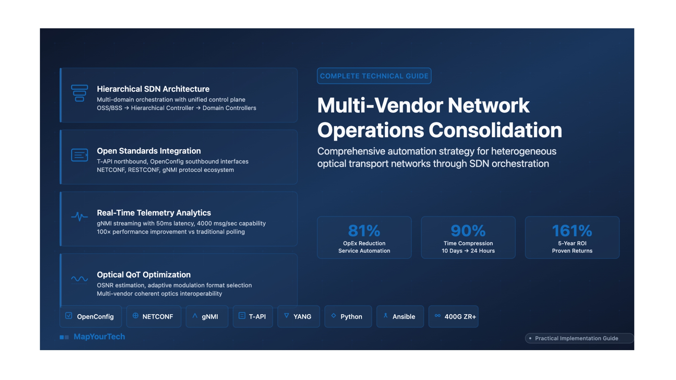
Multi-Vendor Network Operations Consolidation Strategy
Executive Summary & Strategic Foundation
Executive Summary
The management of heterogeneous optical transport networks represents one of the most critical operational challenges facing telecommunications service providers and large-scale network operators in the modern era. As network infrastructures evolve to support exponentially growing data traffic—driven by cloud computing, artificial intelligence workloads, 5G mobile services, and the proliferation of high-bandwidth applications—the architectural complexity of the underlying photonic layer has increased commensurately. Operators have strategically deployed best-of-breed equipment from multiple vendors to avoid technological lock-in and maintain competitive flexibility, creating environments where Ciena transponders coexist with Nokia reconfigurable optical add-drop multiplexers, Infinera line systems interface with Cisco routers, and diverse amplifier technologies from various manufacturers operate within the same optical path.
However, this multi-vendor approach has exposed a fundamental architectural weakness: while the data plane and control plane have achieved remarkable sophistication through dense wavelength division multiplexing, coherent detection technologies, and software-defined networking paradigms, the management plane has largely remained anchored to legacy, vendor-specific paradigms. Each equipment manufacturer provides proprietary network management systems that operate as isolated silos, creating operational inefficiencies that manifest as prolonged service provisioning intervals, excessive manual labor requirements, elevated operational expenditures, and increased risk exposure from coordination failures across domain boundaries.
Key Quantitative Findings
- Research scope and authority: Comprehensive industry surveys of 88 global network operators representing diverse geographic regions and network scales provide authoritative quantification of optical network automation benefits across production deployments
- Operational cost reduction potential: Up to 81% operational expenditure savings in service provisioning and fulfillment workflows, with network lifecycle management automation delivering 56% OpEx reduction across planning, deployment, and maintenance activities
- Service velocity transformation: Service order fulfillment times collapsed from 10 days to 24 hours—achieving 90% operational cost reduction in order-handling processes while enabling competitive positioning improvements of 5× in win rate for major operators
- Capital efficiency gains: Network planning automation and optimized resource utilization enable up to 30% capital expenditure avoidance through intelligent capacity planning, spectrum defragmentation, and legacy equipment retirement strategies
- Return on investment timeline: Structured automation programs achieve positive return within 18-36 months for mid-sized operators, with total 5-year returns of 161% documented through comprehensive TCO analysis including both tangible savings and strategic value creation
- Revenue acceleration: Up to 10% revenue uplift materialized from faster time-to-market for new services, improved SLA compliance, and enablement of on-demand Network-as-a-Service business models previously unachievable with manual operations
- Network scaling efficiency: Automation enables networks to scale 4× in capacity and geographic reach without proportional operational cost increases, addressing the fundamental challenge of traffic growth exceeding revenue growth
The Strategic Imperative
The consolidation of multi-vendor network operations through unified automation ecosystems represents not merely an optimization opportunity but an existential competitive requirement. Network operators face a critical inflection point: the traditional paradigm of managing optical networks through manual processes and vendor-specific tools has become fundamentally untenable. Contemporary network environments exhibit complexity characteristics that exceed human-scale management capabilities—wavelength counts in the hundreds per fiber, modulation formats ranging from binary phase-shift keying to probabilistically shaped quadrature amplitude modulation with 64 or more constellation points, dynamic spectrum allocation across C-band and L-band wavelength ranges, and multi-layer service dependencies spanning optical transport networks, multiprotocol label switching, and Ethernet technologies.
The automation imperative stems from four converging forces: operational cost pressure as service commoditization compresses revenue per bit while traffic volumes expand; service velocity requirements as enterprise customers demand on-demand, application-programming-interface-driven connectivity provisioning measured in minutes rather than weeks; technological complexity acceleration as coherent pluggable optics, artificial intelligence-optimized network architectures, and quantum-safe encryption introduce unprecedented configuration parameter spaces; and competitive necessity as operators implementing comprehensive automation achieve cost structures and service capabilities that create insurmountable advantages over manually-operated competitors.
Critical Operational Challenge: The Silo Problem
Traditional multi-vendor optical network environments exhibit severe operational fragmentation. Each vendor's network management system operates as an isolated island with proprietary interfaces, forcing operations teams to maintain separate expertise pools, duplicate monitoring infrastructure, and execute manual coordination for any cross-domain operation. Industry research quantifies this inefficiency: network engineers expend approximately 42% of their working time on routine maintenance tasks that are prime automation candidates, while manual configuration and troubleshooting activities account for 62.5% of total network operating costs. Service provisioning workflows requiring coordination across multiple vendor domains average 5-7 weeks from order entry to service activation, with human labor costs dominating this interval.
Solution Architecture Overview
The strategic solution framework centers on constructing a unified automation ecosystem that abstracts vendor-specific implementation details while preserving access to advanced, differentiated functionality. This architecture implements a hierarchical control model where standardized, open application programming interfaces and data models enable interoperability across heterogeneous equipment populations. The foundational architectural principles include:
Hierarchical Software-Defined Networking Control: A multi-domain orchestration platform operates above vendor-specific domain controllers, maintaining a unified network topology view and resource inventory while delegating equipment-specific operations to underlying management systems. This "manager of managers" approach enables consistent service provisioning workflows across diverse infrastructure while leveraging deep vendor expertise embedded in domain controllers.
Standards-Based Interface Layer: Open standards provide the critical interoperability substrate. The Transport Application Programming Interface specification from the Open Networking Foundation establishes service-level abstraction for northbound orchestration interfaces, while OpenConfig YANG models define device-level configuration and telemetry for southbound equipment control. These complementary standards enable vendor-agnostic automation workflows that eliminate proprietary integration barriers.
Streaming Telemetry and Analytics: Modern network monitoring transcends legacy Simple Network Management Protocol polling paradigms through gRPC Network Management Interface streaming telemetry, delivering high-resolution performance data with sub-second granularity. This telemetry foundation enables artificial intelligence and machine learning algorithms for predictive failure analysis, quality-of-transmission estimation, and autonomous optimization.
Progressive Implementation Methodology: Risk mitigation through phased deployment follows "crawl-walk-run" maturity progression. Initial phases establish monitoring visibility and automated discovery without configuration risk, intermediate phases introduce controlled provisioning automation on non-critical network segments, and advanced phases implement closed-loop autonomous operations with machine learning optimization.
Use Cases and Application Domains
Multi-vendor network operations consolidation strategies deliver transformative value across diverse operational contexts:
Tier-1 Service Provider Networks: Large telecommunications operators with continental or global infrastructure footprints managing hundreds of thousands of wavelength-kilometers require automation to achieve operational scalability. These organizations typically operate equipment from five or more optical transport vendors alongside multiple router and switch vendors, creating management complexity that exceeds manual coordination capabilities. Automation enables consistent service provisioning, proactive performance optimization, and rapid fault isolation across this heterogeneous infrastructure.
Cloud Service Provider Interconnection: Hyperscale cloud operators and content delivery networks operate dense wavelength division multiplexing infrastructures connecting geographically distributed data centers. These environments demand predictable, low-latency provisioning of high-capacity optical circuits with stringent service level agreements. Automation platforms enable application-programming-interface-driven wavelength services, dynamic bandwidth adjustment responding to traffic patterns, and multi-layer optimization across optical transport and Internet Protocol layers.
Enterprise Wide Area Networks: Large enterprises with private optical networks or managed wavelength services from multiple providers benefit from unified visibility and orchestration capabilities. Automation simplifies the management of hybrid architectures combining owned infrastructure with carrier services, enables rapid deployment of connectivity for merger and acquisition integrations, and provides consistent service quality across heterogeneous transport technologies.
5G Mobile Transport Networks: Fifth-generation mobile networks impose unprecedented demands on optical transport infrastructure through fronthaul, midhaul, and backhaul segments requiring precise timing synchronization, ultra-low latency paths, and dynamic bandwidth allocation. Multi-vendor automation enables coordinated optimization across radio access network elements, optical transport systems, and core packet networks, while supporting network slicing architectures that provide differentiated service classes.
Strategic Implications for Network Operations
The transition to consolidated, automated multi-vendor operations represents more than technological modernization—it constitutes organizational transformation. Network operations departments must evolve from reactive troubleshooting teams to proactive automation engineering organizations. This transformation demands investment in human capital development, with network engineers acquiring software development competencies including Python programming, application programming interface integration patterns, data modeling with YANG schemas, and continuous integration/continuous deployment methodologies. Organizations that successfully navigate this transition transform their network infrastructure from a cost center requiring continuous manual attention into a programmable platform enabling business agility and competitive differentiation.
The competitive dynamics are compelling: operators implementing comprehensive automation achieve operational cost structures 30-50% lower than manually-operated peers, while simultaneously delivering service velocity improvements of 10-20× in provisioning timelines. These combined advantages create compounding competitive effects where automated operators can offer superior service levels at lower price points, accelerating market share gains that further distribute fixed costs across larger customer bases. For operators delaying automation initiatives, the strategic risk extends beyond missed efficiency gains to potential market viability as customers migrate toward providers offering application-programming-interface-driven, on-demand connectivity services that manual operations cannot economically support.
The Genesis of Network Management: From Manual Operations to Element Management
The historical trajectory of optical network management systems traces a continuous evolution from primitive manual operations toward increasingly sophisticated automated frameworks. Understanding this evolution provides essential context for appreciating both the transformative potential of contemporary multi-vendor orchestration platforms and the technical debt that constrains many production networks. The journey from element-centric management through domain controllers to hierarchical software-defined networking architectures represents not merely technological advancement but fundamental paradigm shifts in how network operators conceptualize infrastructure control.
The Era of Manual Configuration: 1980s-1990s
The inaugural generation of optical transport systems operated through direct terminal access and command-line interfaces requiring physical presence at equipment locations. Network engineers configured wavelength-division multiplexing systems, optical amplifiers, and time-division multiplexing equipment through proprietary terminals connected via RS-232 serial interfaces, with each vendor implementing unique command syntaxes, configuration file formats, and operational procedures. This manual paradigm exhibited severe scalability limitations—a single wavelength provisioning operation across ten network elements could require several hours of configuration time, with each equipment interaction introducing transcription error risk and configuration inconsistency potential.
Legacy Protocol Foundation: TL1 (1984-Present)
Transaction Language 1 emerged from Bellcore specifications as the dominant management protocol for North American telecommunications networks. This ASCII-based, human-readable protocol operated through command-response message exchanges, supporting configuration management, fault detection, performance monitoring, and provisioning operations. Despite its 1984 origins, TL1 persists in production networks through 2025+, creating integration challenges as operators bridge legacy equipment into modern automation frameworks. The protocol's longevity stems from extensive deployment in synchronous optical networking equipment and operational staff familiarity, though its verbose syntax, limited data modeling capabilities, and absence of transaction semantics render it inadequate for contemporary automation requirements.
The Simple Network Management Protocol Revolution: 1990s-2005
The Internet Engineering Task Force's standardization of Simple Network Management Protocol in 1988 provided the first widely-adopted, vendor-agnostic network management framework. SNMP introduced Management Information Base schemas defining hierarchical object identifiers for configuration parameters and operational statistics, enabling centralized monitoring platforms to poll diverse equipment through standardized queries. Network management stations could retrieve optical power levels, laser temperatures, bit error rates, and alarming conditions from heterogeneous equipment populations, transforming network visibility.
However, SNMP's architectural limitations became increasingly apparent as network complexity expanded. The protocol's polling paradigm imposed substantial overhead—monitoring a 100-wavelength optical network at 5-minute intervals generated thousands of polling transactions hourly, consuming management network bandwidth and introducing monitoring latency. SNMP's weak security model in versions 1 and 2c exposed management traffic to interception and modification attacks, while version 3's security enhancements saw limited deployment due to configuration complexity. Most critically, SNMP's focus on read-oriented monitoring with limited write capabilities positioned it as unsuitable for configuration management and service provisioning automation.
The Software-Defined Networking Paradigm Shift: 2006-2015
The emergence of software-defined networking principles fundamentally reconceptualized network architecture through separation of control plane intelligence from data plane forwarding, enabling programmable infrastructure through standardized southbound interfaces. While SDN originated in Internet Protocol networking contexts through OpenFlow protocol development, the paradigm's applicability to optical transport networks became increasingly evident as coherent detection technologies, flexible grid wavelength-division multiplexing, and reconfigurable optical add-drop multiplexers created photonic layer programmability opportunities.
NETCONF and the Model-Driven Management Revolution
The IETF's standardization of Network Configuration Protocol in 2006 addressed SNMP's fundamental limitations through introduction of transaction-based configuration management with candidate datastore semantics, atomic commit operations, and rollback capabilities. NETCONF established XML-based remote procedure call mechanisms enabling reliable configuration operations across heterogeneous equipment, while its layered architecture separated transport protocol concerns from operation semantics and content encoding.
The protocol's transformative impact derived from separation of transport mechanism from data modeling—NETCONF defined the communication framework while delegating data structure definition to YANG modeling language. This architectural division enabled vendor-specific extensions while maintaining protocol-level interoperability, allowing equipment manufacturers to expose proprietary capabilities through custom YANG modules while supporting standardized models for common functionality.
The OpenConfig Movement: Operator-Driven Standardization
The OpenConfig project, initiated in 2014 through collaboration among leading network operators including Google, Microsoft, AT&T, and British Telecom, represented a fundamental shift in standards development methodology. Unlike traditional vendor-driven standardization processes where equipment manufacturers defined data models reflecting their implementation architectures, OpenConfig adopted an operator-centric approach where service providers specified models representing actual operational requirements and workflows. This inversion of the standardization paradigm produced models emphasizing practical deployability, operational completeness, and cross-vendor consistency rather than comprehensive feature coverage or implementation flexibility.
Architectural Principles and Design Philosophy
OpenConfig models embody several critical design principles distinguishing them from alternative standardization efforts. First, the initiative prioritizes semantic consistency across models—configuration parameters, operational state representations, and telemetry structures maintain uniform naming conventions, data type selections, and hierarchical organizations regardless of equipment type. A network automation platform managing both optical transponders and packet routers encounters identical state representation patterns, simplifying software development and reducing integration complexity.
Second, OpenConfig explicitly rejects "minimum common denominator" approaches where models support only functionality universally available across all implementations. Instead, models target comprehensive coverage of operationally-relevant capabilities even when specific vendors lack support, utilizing presence containers and optional leafs to accommodate implementation variation. This design philosophy ensures models remain useful as vendor capabilities evolve while maintaining backward compatibility with existing implementations.
Third, the models unify configuration intent with operational state visibility within integrated schemas. Traditional management approaches separated configuration databases from operational state queries, creating synchronization challenges and requiring dual data access patterns. OpenConfig containers typically include both configuration leaves (operator-specified parameters) and state leaves (equipment-reported values), enabling atomic retrieval of intended configuration alongside actual operational status.
Protocol Ecosystem Evolution: From NETCONF to gNMI
The maturation of data modeling standards occurred alongside diversification of transport protocols optimized for distinct use cases. While NETCONF established the foundational paradigm for transaction-based configuration, subsequent protocol developments addressed specific operational requirements including streaming telemetry, lightweight operations, and high-performance data collection.
RESTCONF: Web-Native Network Management
Recognizing that NETCONF's XML encoding and SSH transport imposed integration barriers for web-based applications and lightweight automation tools, the IETF standardized RESTCONF in 2017 as an HTTP-based alternative utilizing RESTful architectural principles. RESTCONF provides stateless operations with standard HTTP methods—GET for data retrieval, POST for resource creation, PUT for replacement, PATCH for modification, and DELETE for removal—enabling integration with conventional web development frameworks and eliminating session management complexity inherent in NETCONF's connection-oriented model.
The protocol's adoption of JSON encoding alongside XML support reduces parsing overhead and improves human readability, though at the cost of eliminating NETCONF's transaction semantics. RESTCONF operations execute immediately without candidate datastore staging or atomic commit capabilities, making the protocol suitable for stateless query operations and simple configuration changes but inappropriate for complex multi-step configuration workflows requiring transactional guarantees.
gNMI: High-Performance Streaming Telemetry
Google's introduction of gRPC Network Management Interface in 2016 addressed fundamental performance limitations in polling-based monitoring approaches. gNMI leverages gRPC's HTTP/2 foundation to establish persistent bidirectional streams supporting subscription-based telemetry delivery, where network elements push state updates to collectors immediately upon change detection rather than awaiting periodic polling queries. This architectural inversion delivers multiple performance advantages: telemetry collection overhead reduces dramatically as devices report only changed values rather than complete state tables, monitoring latency decreases from polling intervals (typically 30-300 seconds) to subsecond update delivery, and management network traffic volume falls by orders of magnitude.
The protocol's most significant operational impact manifests in optical performance monitoring scenarios. Coherent optical systems require continuous surveillance of parameters including optical signal-to-noise ratio, chromatic dispersion, polarization mode dispersion, pre-forward-error-correction and post-forward-error-correction bit error rates, and laser frequency offset. Traditional SNMP-based monitoring polling these metrics at 1-minute intervals for a 100-wavelength network generates approximately 14,400 transactions hourly while introducing 30-second average monitoring latency. gNMI streaming telemetry eliminates polling overhead entirely while delivering parameter updates within milliseconds of value changes, enabling real-time quality-of-transmission assessment and predictive failure analytics.
Industry Standardization Bodies and Their Contributions
The ecosystem of standards organizations contributing to multi-vendor network automation exhibits functional specialization, with each body addressing distinct architectural layers or operational domains. Understanding these organizations' complementary roles clarifies how diverse specifications integrate into cohesive automation frameworks.
Open Networking Foundation: Service-Level Abstraction
The Open Networking Foundation's Transport API specification addresses multi-domain orchestration requirements through technology-agnostic service abstractions. Unlike OpenConfig's device-level focus, Transport API defines northbound interfaces for service orchestration platforms requesting connectivity services without specifying underlying implementation technologies. An orchestrator requesting 100-gigabit Ethernet connectivity between two geographic locations through T-API receives service-level responses indicating feasibility, latency characteristics, and protection options without exposure to wavelength assignments, modulation format selections, or routing path details.
Transport API version 2.1.3, widely deployed in production environments, provides standardized representations for connectivity services, virtual network services, and path computation requests. The specification's technology neutrality enables identical interface patterns whether underlying transport utilizes optical transport networking, multiprotocol label switching, or segment routing architectures, simplifying multi-domain service orchestration across heterogeneous network segments. Major SDN controller platforms including Nokia Network Services Platform, Ciena Blue Planet, and Cisco Crosswork expose T-API northbound interfaces, enabling interoperability at the orchestration layer even when managing vendor-specific equipment through proprietary southbound interfaces.
Telecom Infra Project: Open Disaggregation
The Telecom Infra Project's Open Optical Packet Transport initiative promotes disaggregated optical network architectures where transponders, wavelength-selective switches, amplifiers, and multiplexers from diverse vendors interoperate within unified line systems. This disaggregation philosophy contrasts with traditional vertically-integrated architectures where single vendors supply complete optical transport solutions. The MUST (Mandatory Use Case Requirements for SDN for Transport) specification, endorsed by operators including Telefónica, Vodafone, Orange, and MTN, mandates specific standardization requirements for production deployment including Transport API compliance, OpenConfig data model support, and standardized performance monitoring.
The initiative's practical impact manifests through validation programs where multi-vendor equipment combinations undergo interoperability testing. The Phoenix Silver badge certification verifies that optical line systems support alien wavelengths from third-party transponder vendors, with comprehensive testing covering optical power budgets, chromatic dispersion compensation, and amplifier gain dynamics. Equipment achieving certification demonstrates production-ready interoperability, reducing integration risk for operators deploying multi-vendor architectures.
Metro Ethernet Forum and TM Forum: Service Lifecycle Standards
The Metro Ethernet Forum's Lifecycle Service Orchestration framework and TM Forum's Open API specifications address service-layer orchestration requirements extending beyond transport connectivity. MEF LSO defines standardized interfaces for Ethernet service provisioning, activation, modification, and decommissioning across multi-provider networks, enabling automated service delivery when connectivity spans multiple operator domains. The framework's polymorphic API design allows identical interface patterns whether underlying transport utilizes optical wavelengths, MPLS pseudowires, or segment routing paths.
TM Forum specifications including TMF630 (REST API Design Guidelines), TMF641 (Service Ordering), and TMF638 (Service Inventory) provide comprehensive business-to-operations-systems and operations-systems-to-operations-systems integration frameworks. These specifications enable automated service fulfillment workflows spanning customer order entry through network resource assignment, service activation, and billing record generation, with optical transport provisioning representing one component within end-to-end service delivery processes.
From Theory to Practice: Real-World Deployment Milestones
The maturation of standards specifications from experimental prototypes to production-deployed technologies occurred through progressive industry validation. Several milestone deployments demonstrated that standards-based multi-vendor automation transcended laboratory demonstrations to achieve carrier-grade reliability and operational scalability.
The Ciena-BT Multi-Vendor Trial (August 2024)
A particularly significant validation occurred when Ciena and BT Group demonstrated production-grade multi-vendor interoperability managing WaveLogic 5 Nano coherent pluggables within third-party router platforms through unified control plane. The implementation utilized OpenConfig data models for configuration management and gNMI for streaming telemetry, with Ciena's Navigator Network Control Suite providing centralized orchestration across heterogeneous equipment populations. The trial achieved full operational parity including automated topology discovery, alarm correlation across vendor boundaries, and performance monitoring encompassing both optical layer parameters and higher-layer service metrics.
This milestone transcended previous proof-of-concept demonstrations by operating within BT's production network environment under actual traffic conditions, validating that standards-based management could achieve reliability and performance characteristics matching proprietary integrated solutions. The success demonstrated that open standards had matured beyond experimental status to production readiness, providing operators with viable alternatives to vendor-locked architectures.
Disaggregated Network Deployments
Multiple tier-1 operators have deployed production networks utilizing disaggregated architectures where line systems support transponders from multiple vendors. These deployments validate both technical interoperability and operational viability of multi-vendor approaches. Network operators report that while integration complexity initially exceeds homogeneous deployments, operational benefits including vendor competition, technology choice flexibility, and avoiding obsolescence risk offset implementation costs within 18-36 month timeframes.
Hierarchical SDN Architecture: The Foundational Framework
The technical architecture for multi-vendor network operations consolidation adheres to hierarchical Software-Defined Networking principles that establish clear separation of concerns across operational layers. This architectural paradigm, aligned with industry frameworks including the Open Networking Foundation's SDN Architecture for Transport Networks and the IETF's Abstraction and Control of Traffic Engineered Networks specifications, provides the essential foundation for achieving vendor-agnostic automation while preserving access to advanced, differentiated functionality offered by individual equipment manufacturers.
The hierarchical model addresses a fundamental challenge in multi-vendor environments: balancing standardization requirements for interoperability against the operational necessity of leveraging vendor-specific capabilities that provide competitive advantages. Rather than pursuing a homogenizing approach that reduces all equipment to least-common-denominator functionality, the architecture implements layered abstractions where each tier provides appropriate visibility and control granularity for its operational domain while exposing standardized northbound interfaces to higher layers.
Architectural Principle: Separation of Abstraction Layers
The hierarchical architecture stratifies network management into distinct operational layers, each serving specific purposes within the automation ecosystem. Network abstraction at higher operational layers focuses on policy creation, service orchestration, and holistic resource management, providing unified views of network capabilities without exposure to implementation details. Lower layers handle granular control and configuration of individual network elements, ensuring efficient resource utilization and optimization while maintaining equipment-specific operational modes.
This hierarchy facilitates integration of diverse technologies and vendor-agnostic solutions, enabling seamless interoperability across multi-vendor environments while eliminating vendor lock-in associated with closed, proprietary management platforms. The layered approach permits independent evolution of each architectural tier—standards bodies can enhance service-level abstractions without disrupting device-level implementations, while equipment vendors can introduce advanced capabilities that orchestration layers access through standardized extension mechanisms.
Layer 1: Network Element Layer
The foundation of the hierarchical architecture comprises the physical and virtual network elements performing actual data plane operations. This layer includes optical transponders and muxponders executing coherent detection and modulation, reconfigurable optical add-drop multiplexers providing wavelength routing and spectrum management, optical amplifiers maintaining signal power across fiber spans, optical line systems managing chromatic dispersion compensation and optical supervisory channels, and packet layer equipment including routers and switches interfacing with optical transport infrastructure.
Network elements expose southbound management interfaces through which domain controllers execute configuration operations and retrieve operational state. The interface technologies at this layer exhibit significant vendor diversity—while modern equipment increasingly supports NETCONF and YANG data models, legacy systems may require TL1 protocol translation, SNMP mediation, or vendor-specific command-line interface automation. The hierarchical architecture accommodates this heterogeneity by delegating protocol translation responsibilities to domain controllers rather than imposing unrealistic uniformity requirements on equipment populations exhibiting decades of technology evolution.
Layer 2: Domain Controllers
Domain controllers provide technology-specific or vendor-specific management capabilities for equipment populations within defined network segments. A large-scale operator typically deploys separate domain controllers for IP/MPLS networks, optical transport networks, microwave backhaul systems, and potentially additional domains for specific vendor equipment families. Each domain controller maintains detailed topology models, resource inventories, and operational state for its managed equipment population, executing provisioning workflows, fault management procedures, and performance monitoring appropriate to its technology domain.
The critical architectural function of domain controllers manifests in their dual interface responsibilities. Southbound toward network elements, controllers employ whatever protocols and procedures necessary to achieve effective equipment management—whether NETCONF transactions, TL1 command sequences, SNMP operations, or proprietary APIs. Northbound toward hierarchical orchestrators, controllers expose standardized, technology-agnostic interfaces based on Transport API specifications, OpenConfig data models, or domain-specific standards appropriate to their architectural position.
This architectural pattern enables pragmatic multi-vendor integration strategies. Operators can deploy vendor-supplied domain controllers for equipment families where manufacturers provide sophisticated management platforms embodying deep product knowledge, while utilizing open-source or third-party controllers for domains requiring vendor-neutral coordination. The standardized northbound interfaces ensure that orchestration layer workflows remain independent of domain controller implementation choices, providing organizational flexibility in balancing vendor relationships against operational requirements.
Layer 3: Hierarchical SDN Controllers
The hierarchical controller layer provides multi-domain coordination, implementing service orchestration workflows that span technology boundaries and vendor domains. This tier maintains unified network topology views synthesized from domain controller representations, abstract resource inventories enabling constraint-based path computation across heterogeneous infrastructure, and service lifecycle management coordinating provisioning, modification, and decommissioning operations across multiple domains.
Hierarchical controllers implement the "manager of managers" architectural pattern where high-level service requests decompose into domain-specific operations delegated to underlying controllers. When an orchestrator receives a request for 100-gigabit Ethernet connectivity between geographic locations, the hierarchical controller performs multi-domain path computation considering available optical wavelengths, packet layer capacity, protection requirements, and quality-of-transmission constraints. The computed service path may traverse IP/MPLS segments managed by one domain controller, optical transport networks controlled by another, and microwave backhaul links supervised by a third controller—the hierarchical tier coordinates configuration operations across all involved domains while maintaining transactional semantics ensuring either complete service activation or clean rollback upon encountering provisioning failures.
Layer 4: OSS/BSS Orchestration
The uppermost architectural layer comprises Operations Support Systems and Business Support Systems providing customer-facing service catalogs, order management, fulfillment workflows, and billing integration. This layer abstracts network connectivity into business services—wavelength transport, Ethernet virtual private lines, Layer 3 VPN connectivity, bandwidth-on-demand offerings—presented through customer portals with self-service ordering capabilities or exposed through business-to-business APIs enabling automated service provisioning by enterprise customers and partner networks.
OSS/BSS systems interact with hierarchical controllers through service-oriented APIs based on TM Forum Open API specifications and MEF Lifecycle Service Orchestration frameworks. A customer order for inter-datacenter connectivity translates into service requests decomposed by orchestration workflows into network resource allocations, configuration operations delegated to hierarchical controllers, activation verification procedures, and billing record generation—all coordinated through automated fulfillment processes minimizing manual intervention.
Standardized Interface Specifications: The Interoperability Foundation
The hierarchical architecture's effectiveness depends entirely upon standardized interfaces enabling interoperability across organizational and vendor boundaries. The interface specifications divide into northbound APIs serving orchestration and business systems, southbound protocols managing network elements, and east-west interfaces coordinating peer domain controllers in multi-operator scenarios.
Northbound Interface: Transport API (T-API)
The Open Networking Foundation's Transport API specification provides the definitive northbound interface standard for optical network domain controllers. T-API version 2.1.3, widely deployed in production environments, defines service-level abstractions enabling orchestrators to request connectivity services without exposure to underlying implementation technologies. The specification provides YANG data models representing connectivity services (point-to-point and multipoint), virtual network services enabling customer network slicing, path computation services for constraint-based routing, and notification mechanisms for topology changes and service state transitions.
T-API's architectural significance manifests through its technology-agnostic service abstractions. An orchestrator requesting 100-gigabit connectivity between service endpoints specifies desired bandwidth, latency constraints, protection requirements (unprotected, 1+1 protection, 1:N restoration), and service level agreement parameters without indicating whether fulfillment utilizes optical transport networking, wavelength-division multiplexing, or multiprotocol label switching technologies. The domain controller receiving this abstract service request performs technology mapping, resource allocation, and constraint verification appropriate to its managed infrastructure, responding with either service confirmation including allocated resources and computed paths or rejection messages indicating constraint violations.
- Service-level abstraction for connectivity requests
- Technology-agnostic service models
- RESTCONF over HTTPS transport
- YANG data modeling framework
- Version 2.1.3 widely deployed
- OIF interoperability validation
- Multi-domain coordination support
- Operator-driven YANG models
- Vendor-neutral device abstraction
- Terminal device, optical amplifier models
- Wavelength router, transceiver models
- Continuous model evolution (2024-2025+)
- Semantic consistency across vendors
- Configuration + state unified representation
- Transaction-based configuration operations
- Candidate datastore with validation
- Atomic commit and rollback
- SSH/TLS transport security
- XML encoding (verbose but reliable)
- Session-based operation
- Industry-standard since 2006
- gRPC/HTTP2 bidirectional streaming
- Subscribe-based telemetry delivery
- Protocol Buffer encoding efficiency
- 4000 msg/sec, 50ms latency capability
- 100× performance vs SNMP polling
- Real-time operational state visibility
- On-change and sampled subscriptions
- RESTful HTTP operations
- JSON and XML encoding support
- Stateless transaction model
- Easy web application integration
- YANG model compatibility
- No candidate datastore semantics
- Lightweight for simple operations
- TMF630: REST API design guidelines
- TMF641: Service ordering API
- TMF638: Service inventory API
- Business-to-OSS integration
- OSS-to-OSS coordination
- Multi-provider service chains
- Polymorphic API design patterns
Southbound Interfaces: OpenConfig and Device Protocols
OpenConfig YANG models provide vendor-neutral device configuration and operational state representations enabling controllers to manage heterogeneous equipment through common data structures. The models decompose optical network equipment into reusable components—platforms representing chassis and line cards, terminal devices modeling transponders and muxponders, optical amplifiers including erbium-doped fiber amplifiers and Raman amplifiers, wavelength routers representing reconfigurable optical add-drop multiplexers, and optical channel monitors providing spectrum analysis capabilities.
Each model defines configuration parameters controllers may set (target optical output power, operating wavelength, modulation format selection), operational state values equipment reports (current optical power, pre-forward-error-correction and post-forward-error-correction bit error rates, chromatic dispersion measurements), and derived state calculations controllers perform (available margin, quality-of-transmission estimates). The unified configuration and state representation within single models simplifies controller implementation—applications retrieve both intended configuration and actual operational status through identical data paths, enabling immediate verification of configuration application and detection of equipment-reported anomalies.
Protocol selection for OpenConfig model transport depends on operational requirements. NETCONF provides robust transactional semantics suitable for configuration operations where atomic commit and rollback capabilities ensure network consistency—either all configuration changes within a transaction apply successfully or the entire operation rolls back, preventing partial configuration states. RESTCONF offers lightweight alternative for stateless operations where web application integration priorities outweigh transaction semantics. The gNMI protocol revolutionizes operational state monitoring through streaming telemetry subscriptions, where equipment pushes state updates to collectors upon detecting value changes rather than awaiting periodic polling requests.
Protocol Performance Comparison: Streaming Telemetry Revolution
Traditional SNMP polling of a 100-wavelength optical network at 5-minute intervals generates approximately 14,400 poll transactions hourly while introducing 150-second average monitoring latency (half the polling interval). Each poll consumes management network bandwidth, processor cycles on both management station and network element, and introduces opportunities for polling failures requiring retry logic.
gNMI streaming telemetry eliminates polling overhead entirely. Equipment establishes persistent gRPC streams to telemetry collectors, pushing parameter updates immediately upon value changes. For optical power monitoring requiring 0.1 dBm resolution, equipment transmits updates only when power changes exceed this threshold rather than reporting unchanged values every 5 minutes. Industry implementations demonstrate 100× reduction in management traffic volume while achieving sub-second monitoring latency—optical signal degradation detection improves from 5-minute discovery intervals to near-instantaneous alerting enabling proactive intervention before service impact.
Component Interactions and Data Flow Patterns
Understanding data flow patterns across architectural layers illuminates how abstract service requests transform into device-specific configuration operations while maintaining visibility and control throughout provisioning workflows. The interaction sequences demonstrate both success paths where services activate successfully and failure scenarios requiring coordinated rollback across multiple domains.
Service Provisioning Workflow
The canonical service provisioning sequence begins when customer-facing systems receive connectivity requests through web portals, business-to-business APIs, or operator service desks. The OSS layer validates customer authorization, service feasibility against available inventory, and pricing calculations before generating service orders forwarded to orchestration systems. The orchestrator decomposes high-level service requests into network resource allocations—for inter-datacenter 100-gigabit Ethernet connectivity, this may include IP/MPLS layer-3 VPN endpoints, optical wavelength transport across multiple fiber spans, and potential microwave or satellite backup paths for resilience.
Multi-domain path computation executes next, where the hierarchical controller queries domain controllers for available resources, computes end-to-end paths satisfying latency and protection constraints, and reserves resources pending configuration completion. The optical domain controller performs wavelength assignment selecting available spectrum channels, quality-of-transmission calculations verifying that optical signal-to-noise ratios support desired modulation formats across computed fiber paths, and routing optimizations balancing traffic loads across reconfigurable optical add-drop multiplexer ports.
Configuration execution proceeds through domain-specific workflows. The optical domain controller translates abstract wavelength service requests into device-specific operations: configuring transponder wavelength tuning and modulation format selection via OpenConfig terminal-device models over NETCONF, programming reconfigurable optical add-drop multiplexer wavelength-selective switches through wavelength-router models establishing cross-connections, and adjusting optical amplifier target gains through amplifier models maintaining signal power across fiber spans. Meanwhile, the IP/MPLS domain controller configures router interfaces, establishes label-switched paths, and instantiates virtual routing and forwarding instances for layer-3 VPN isolation.
Fault Management and Service Assurance
Continuous monitoring through streaming telemetry provides real-time service assurance capabilities detecting degradation before customer impact. Equipment streams operational parameters including optical power levels, bit error rates, signal-to-noise ratios, and protocol state transitions to centralized telemetry collectors. Analytics platforms correlate telemetry across network layers—optical signal degradation correlating with increased packet loss, or router interface flapping coinciding with optical path instability—enabling root cause identification across multi-vendor boundaries.
When faults occur, the hierarchical architecture coordinates response through layered alarm correlation. Network elements generate primitive alarms reporting local conditions (laser failure, fiber cut, protocol timeout). Domain controllers aggregate primitive alarms into higher-level fault indications correlating related events—fiber cut generating hundreds of wavelength loss alarms consolidates into single fiber fault indication. The hierarchical controller performs cross-domain correlation identifying service-impacting faults from infrastructure failures, prioritizing restoration activities based on affected customer services rather than raw alarm volumes.
Fundamental Concepts and Terminology
Precise terminology provides the foundation for technical discourse regarding multi-vendor network automation. The following definitions establish common vocabulary encompassing architectural patterns, operational concepts, and performance metrics essential for understanding automation strategies and their quantitative impacts.
Mathematical Models for Automation Economics
Quantitative analysis of multi-vendor automation initiatives requires rigorous mathematical frameworks capturing operational costs, capital expenditures, and revenue impacts. The following models provide structured methodologies for calculating return on investment, total cost of ownership, and operational efficiency metrics essential for business case development and program performance tracking.
Return on Investment (ROI) Model
The fundamental return on investment calculation quantifies the financial benefit relative to investment cost over a defined analysis period. For multi-vendor automation initiatives, comprehensive ROI models incorporate both tangible cost savings (reduced operational expenditures, capital expenditure avoidance) and strategic value creation (revenue acceleration through improved service velocity, market share gains from competitive positioning advantages).
ROI Calculation Framework
| Variable | Description | Typical Range | Measurement Period |
|---|---|---|---|
| Initial CapEx | Upfront capital expenditure for automation platform licenses, hardware infrastructure, integration services, and initial training | $400K - $1.8M | One-time (Year 0) |
| Annual OpEx | Recurring operational expenditure including software maintenance subscriptions, continuous training, support contracts, and quality assurance | $175K - $475K | Annual |
| Labor Savings | Reduction in manual operational labor through automation of provisioning, monitoring, and troubleshooting workflows | 30-56% of baseline OpEx | Annual |
| CapEx Avoidance | Deferred equipment purchases through improved capacity utilization, extended asset lifecycles, and optimized network planning | 20-30% of equipment budget | Annual |
| Revenue Uplift | Incremental revenue from faster service delivery, improved win rates, and enablement of premium on-demand service offerings | 5-10% of service revenue | Annual |
Example Calculation (Mid-Sized Operator, 5-Year Analysis):
Operational Efficiency Metrics
Operational efficiency quantification requires tracking multiple performance indicators capturing automation's impact across network lifecycle activities. The following mathematical models formalize efficiency calculations for service provisioning, fault resolution, and capacity planning workflows.
Service Provisioning Time Reduction
Industry Benchmark Values:
- T_manual: 10 days (240 hours) - typical manual wavelength service provisioning
- T_automated: 24 hours - automated provisioning via orchestration platform
- Reduction: [(240 - 24) / 240] × 100% = 90%
- Annual savings for 500 services: $75/hour × 216 hours × 500 = $8.1M
Mean Time to Repair (MTTR) Improvement
Example Calculation:
Network Capacity Optimization Models
Automated capacity planning and spectrum management enable more efficient utilization of existing optical infrastructure, deferring capital expenditures for network expansion. The optimization models quantify capacity gains achievable through defragmentation algorithms, dynamic routing, and quality-of-transmission-aware wavelength assignment.
Spectrum Utilization Efficiency
Example Analysis:
Computational Complexity Considerations
Multi-domain path computation and resource optimization problems exhibit significant computational complexity, particularly in large-scale networks with hundreds of nodes and thousands of potential paths. The wavelength assignment problem with quality-of-transmission constraints is NP-hard, requiring heuristic algorithms for practical solution times.
Path Computation Complexity: For a network with N nodes and average node degree D, exhaustive path enumeration yields O(D^N) potential paths between node pairs. Practical implementations employ constraint-based shortest path algorithms (Dijkstra variants) with O(N²log(N)) complexity, augmented with quality-of-transmission estimation reducing solution space through infeasible path elimination.
Multi-Domain Coordination Complexity: Cross-domain path computation involving K domains requires inter-domain constraint negotiation with O(K²) messaging complexity in fully-meshed architectures or O(K) in hierarchical orchestration models, demonstrating architectural efficiency advantages of hierarchical SDN approaches.
Quality of Transmission Mathematical Framework
Optical signal quality estimation provides the foundation for automated wavelength provisioning decisions, determining whether proposed optical paths support desired modulation formats and bit rates. The quality-of-transmission framework incorporates fiber chromatic dispersion, polarization mode dispersion, optical signal-to-noise ratio degradation, and nonlinear impairments to predict bit error rates before wavelength activation.
Optical Signal-to-Noise Ratio (OSNR) Budget
OSNR Accumulation Model
Example OSNR Calculation (10-Span System):
Modulation Format Selection Criteria
Quality-of-transmission estimation enables automated modulation format selection optimizing spectral efficiency while ensuring bit error rate requirements. Higher-order modulation formats (64-QAM, 256-QAM) provide superior spectral efficiency but require higher OSNR, creating tradeoffs between capacity and reach.
Required OSNR for Target Bit Error Rate
| Modulation | Bits/Symbol | Required OSNR (dB) | Spectral Efficiency | Typical Reach |
|---|---|---|---|---|
| BPSK | 1 | 9-11 | 1 bit/s/Hz | >2000 km |
| QPSK | 2 | 12-14 | 2 bits/s/Hz | 1000-2000 km |
| 8-QAM | 3 | 15-17 | 3 bits/s/Hz | 600-1000 km |
| 16-QAM | 4 | 18-20 | 4 bits/s/Hz | 400-600 km |
| 64-QAM | 6 | 24-26 | 6 bits/s/Hz | 100-300 km |
| 256-QAM | 8 | 30-32 | 8 bits/s/Hz | <100 km |
Automated Modulation Format Optimization
Automation systems leverage quality-of-transmission estimation to maximize spectral efficiency while ensuring service reliability. For each wavelength provisioning request, the system computes end-to-end OSNR for candidate paths, evaluates margin against modulation format thresholds, and selects the highest-order modulation format providing adequate performance margin.
Optimization Algorithm:
- Compute available OSNR for candidate path using accumulated noise model
- Evaluate OSNR margin for each modulation format: Margin = OSNR_available - OSNR_required
- Select highest spectral efficiency format with margin ≥ 3 dB (safety threshold)
- If all formats fail margin requirement, reject path or propose alternative routing
- Provision wavelength with selected modulation format and verify post-activation BER
Example Decision: For OSNR_available = 20 dB, system selects 16-QAM (required: 18 dB, margin: 2 dB marginally acceptable) rather than 64-QAM (required: 24 dB, margin: -4 dB insufficient). This automated decision maximizes capacity while ensuring service reliability without manual engineering intervention.
Network Scaling and Growth Models
Understanding network scaling dynamics quantifies automation's long-term value proposition beyond immediate operational savings. As networks expand in geographic scope, wavelength counts, and service complexity, manual operational models exhibit super-linear cost growth while automated approaches maintain near-constant marginal operational costs per incremental capacity unit.
Operational Cost Scaling Analysis
Cost Scaling Models: Manual vs. Automated Operations
Example Comparison (5-Year Growth Projection):
Phased Implementation Methodology: The "Crawl-Walk-Run" Framework
Successful multi-vendor automation programs follow structured, risk-mitigated deployment pathways that progressively build organizational capability, technical infrastructure, and stakeholder confidence. The crawl-walk-run methodology provides proven framework for transitioning from manual operations through monitored automation to fully autonomous network management, with each phase delivering measurable value while establishing foundations for subsequent advancement.
The phased approach addresses fundamental transformation challenges inherent in automation initiatives. Network operations teams possess deep domain expertise in optical transport technologies, troubleshooting methodologies, and vendor-specific equipment behaviors developed over decades of manual operations experience. However, automation requires complementary competencies including software development practices, application programming interface integration patterns, data modeling with YANG schemas, and version control workflows using continuous integration and continuous deployment methodologies. Attempting immediate transition to autonomous operations risks overwhelming teams, triggering stakeholder resistance, and creating service disruptions that undermine program support.
The crawl-walk-run framework mitigates these risks through progressive capability building. Each phase targets specific operational domains, implements non-disruptive technologies first, demonstrates tangible value justifying continued investment, and develops team competencies enabling subsequent phase execution. Industry data indicates operators following structured phased approaches achieve 85-90% automation adoption rates within 18-36 months, while organizations attempting big-bang deployments experience 60-70% failure rates manifesting as abandoned platforms, persistent manual workarounds, or costly program restarts.
Phase 1: Crawl - Foundation Building (Months 0-6)
The crawl phase establishes technical and organizational foundations without introducing configuration change risk. Network discovery automation replaces manual spreadsheet-based inventory tracking with dynamic topology models automatically populated through NETCONF capabilities exchange, LLDP neighbor discovery, and routing protocol database analysis. This automated discovery provides unified view of multi-vendor equipment populations, identifying firmware versions, module configurations, and interconnection topologies across previously siloed domain management systems.
Streaming telemetry deployment constitutes the crawl phase's most impactful technical initiative. Operators transition from SNMP polling to gNMI subscriptions, enabling high-resolution performance monitoring with 50-100 millisecond update intervals versus 5-minute polling cycles. Telemetry collectors aggregate optical power levels, bit error rates, signal-to-noise ratios, protocol states, and environmental parameters from thousands of interfaces, storing time-series data in analytics platforms for trend analysis, anomaly detection, and predictive failure modeling.
Crawl Phase Deliverables and Success Criteria
- Automated Network Discovery: Complete topology map of all optical and packet layer equipment, automatically updated within 15 minutes of topology changes
- Streaming Telemetry Coverage: Minimum 80% of critical interfaces streaming performance metrics at sub-minute granularity
- Centralized Monitoring Dashboard: Unified visibility across multi-vendor domains replacing 5+ siloed management systems
- Read-Only API Integration: Northbound interfaces exposed for OSS/BSS integration without write access minimizing risk
- Team Capability Development: 100% of operations staff completing 40-80 hours of training on automation fundamentals, YANG models, and platform operation
- Documentation: As-built architecture diagrams, operational procedures, and troubleshooting guides establishing knowledge base
Risk Profile: Minimal - all activities are read-only without network configuration changes. Failures impact monitoring visibility but cannot cause service disruptions.
Value Realization: Immediate visibility improvements enable faster troubleshooting (20-30% MTTR reduction), proactive maintenance identification, and capacity planning optimization. Stakeholders observe tangible benefits building confidence for subsequent phases.
Phase 2: Walk - Controlled Automation (Months 6-18)
The walk phase introduces configuration automation in carefully controlled environments minimizing production risk while demonstrating operational efficiency gains. Initial automation targets laboratory networks, test segments isolated from customer traffic, or non-critical services where configuration errors impact limited user populations. This risk-graduated approach enables teams to develop automation competencies, validate workflow correctness, and refine procedures before production deployment.
Workflow template development focuses on high-value, high-frequency operations consuming disproportionate manual labor. Typical early automation targets include wavelength provisioning on test segments, automated configuration backup and restoration for disaster recovery, firmware upgrade orchestration across multi-vendor equipment populations, and compliance verification scanning configuration databases for security policy violations or operational best practice deviations. Each workflow undergoes extensive validation cycles with peer reviews, automated testing against virtual network environments, and phased rollouts to progressively larger equipment populations.
Walk Phase Implementation Strategy
- Isolated Deployment Domains: Select 2-3 non-critical network segments representing diverse vendor equipment for initial automation deployment
- Workflow Prioritization: Develop 10-15 automation workflows targeting operations consuming 60%+ of manual labor hours (provisioning, backup, compliance)
- Continuous Integration Pipeline: Establish GitOps workflows with version control, automated testing, peer review gates, and rollback procedures
- Change Management Integration: Automation workflows participate in existing change control processes with enhanced pre-change validation and automated rollback
- Performance Baselining: Measure provisioning time, error rates, labor hours, and quality metrics before and after automation enabling quantitative benefit demonstration
- Stakeholder Communication: Regular reporting on automation achievements, lessons learned, and risk mitigation effectiveness maintaining executive support
Success Criteria: 50+ successful automated service provisions, sub-5% error rate, 40-60% time savings versus manual operations, zero production-impacting incidents from automation failures, 100% rollback success rate for failed operations.
Phase 3: Run - Production Scale Deployment (Months 18-36)
The run phase extends proven automation workflows to full production environments, implements multi-domain orchestration coordinating IP and optical layers, and deploys advanced capabilities including closed-loop optimization and artificial intelligence-driven analytics. This phase realizes transformational operational efficiency gains and competitive advantages justifying multi-year automation investments.
Multi-domain orchestration implementation coordinates end-to-end service provisioning across hierarchical controller architectures. High-level service requests decompose into coordinated operations across IP/MPLS routers, optical transponders, reconfigurable optical add-drop multiplexers, and potentially microwave or satellite backup paths. The orchestration platform maintains service lifecycle state, executes atomic multi-step provisioning with transaction semantics, and provides unified service assurance correlating alarms and performance degradation across technology boundaries.
Run Phase Transformation Outcomes
Operational Efficiency Achievements:
- 70-85% automation coverage across network lifecycle operations (provisioning, modification, decommissioning, troubleshooting)
- Service provisioning timelines compressed from 10 days to sub-24 hours enabling on-demand customer self-service
- Operational expenditure reduction of 56-81% through labor automation and efficiency improvements
- Mean time to repair improvement from 4 hours to sub-1 hour through automated fault correlation and restoration
- Network capacity scaling 4× without proportional operational cost increases demonstrating sustained competitive advantage
Strategic Capabilities Enabled: Intent-based networking with policy-driven service delivery, predictive analytics identifying failures 48-72 hours before occurrence, autonomous network optimization adjusting routing and spectrum allocation based on traffic patterns, customer self-service portals with real-time feasibility checking and automated provisioning, network-as-a-service business models with consumption-based pricing.
Platform Selection and Technology Evaluation
Automation platform selection represents critical architectural decision with multi-year implications for operational capabilities, vendor relationships, and technical debt accumulation. The evaluation framework balances multiple competing priorities including multi-vendor support breadth, standards compliance depth, operational team skillset alignment, total cost of ownership considerations, and strategic roadmap compatibility with organizational objectives.
Commercial Platform Comparison
| Platform | Primary Strengths | Multi-Vendor Approach | Best Fit Scenarios | Considerations |
|---|---|---|---|---|
| Nokia NSP | Comprehensive IP/optical/microwave automation, 1000+ operator deployments, modular architecture | Strong Nokia integration, multi-vendor via standards (NETCONF, OpenConfig, REST APIs) | Service providers with large IP/MPLS + optical networks, Nokia equipment environments, 5G transport automation | Ongoing GUI improvements requested, learning curve for full platform mastery |
| Ciena Blue Planet | Cloud-native microservices, multi-cloud networking, adaptive network control, AI-driven optimization | Vendor-agnostic through open APIs, TOSCA/YANG models, standards-first approach | Multi-cloud connectivity, brownfield multi-vendor networks, operators prioritizing vendor neutrality | Prevents 95% of outages via proactive operations, strong analytics capabilities |
| Cisco Crosswork + NSO | Routed Optical Networking convergence, hierarchical multi-domain orchestration, 35% CapEx + 57-84% OpEx validated savings | Network Element Drivers (NEDs) for multi-vendor, 6-8 week integration for new vendors, adapters for Nokia NSP and Ciena MCP | IP-optical convergence priority, large service providers modernizing transport, Cisco ecosystem investments | 200+ RON customers, strongest IP/optical integration, proven cost reductions |
| Open Source (ONAP, OpenDaylight) | Zero licensing cost, full customization, community collaboration, carrier-grade capabilities proven | Standards-based architecture (T-API, OpenConfig, OpenROADM MSA), multi-vendor by design | Organizations with strong internal development teams, customization requirements, avoiding vendor lock-in | Requires dedicated integration effort, ongoing maintenance responsibility, steeper learning curve |
| Adtran Mosaic | Smooth migration from legacy to automated control, NMS + SDN domain controller combined, zero-touch provisioning | TIP OOPT MUST compliance, disaggregated architecture support, multi-vendor management | Operators transitioning gradually from manual operations, proven migration paths, open optical transport | Ensemble Edge Cloud provides cloud-native automation, FSP 3000 platform integration |
| Ribbon Muse | Programmable optical networking, low-code automation, Apollo platform integration, layer-1 encryption | Open optical line system supporting alien wavelengths, multi-vendor performance monitoring | Programmable ROADMs (2-20 degree), OTN switching automation, C+L band expansion needs | 140Gbaud technology leadership, Rogers Communications national deployment, hitless upgrades |
Platform Selection Criteria Framework
- Standards compliance (OpenConfig, T-API, NETCONF/YANG coverage)
- Multi-vendor equipment support breadth across optical and packet domains
- API richness and documentation quality for custom integration
- Telemetry and analytics capabilities including AI/ML readiness
- Scalability to anticipated network growth (devices, services, transactions/second)
- High availability architecture with geographic redundancy support
- Team skillset alignment (network engineers vs. software developers)
- Learning curve and time-to-productivity for operations staff
- Integration with existing OSS/BSS systems and workflows
- Change management process compatibility and rollback capabilities
- Troubleshooting visibility and diagnostic tooling adequacy
- Operational documentation completeness and quality
- Vendor roadmap alignment with organizational technology strategy
- Multi-cloud networking capabilities if relevant to business model
- 5G transport automation support for mobile operators
- Network slicing and service differentiation capabilities
- Intent-based networking maturity and closed-loop optimization
- Ecosystem partnerships and third-party integration marketplace
- Total cost of ownership over 5-year planning horizon
- Licensing model alignment (perpetual vs. subscription, device-based vs. capacity)
- Professional services requirements for deployment and integration
- Ongoing support and maintenance cost structure
- Vendor lock-in risk and migration path flexibility
- Return on investment timeline and payback period
- Production deployment track record and reference customers
- Vendor financial stability and long-term viability
- Security architecture and vulnerability management practices
- Disaster recovery capabilities and business continuity planning
- Regulatory compliance support (data sovereignty, privacy)
- Upgrade path stability and backward compatibility commitment
- AI/ML integration maturity for predictive analytics and optimization
- Digital twin capabilities for pre-deployment validation
- Quantum-safe networking preparedness and encryption support
- Open-source community engagement and contribution level
- Research partnerships and academic collaboration indicators
- Patent portfolio strength in relevant automation domains
Critical Selection Pitfalls to Avoid
Overemphasis on Feature Checklists: Vendor demonstrations showcase comprehensive feature sets, but operational teams utilize 20-30% of capabilities in typical deployments. Prioritize depth in required functionality over breadth across all possible features. A platform excelling in core provisioning and monitoring workflows delivers more value than one offering 100 mediocre capabilities.
Underestimating Integration Complexity: Multi-vendor environments command 25-50% integration cost premiums versus single-vendor architectures. Budget adequately for adapter development, YANG model customization, workflow testing, and ongoing maintenance of integrations as vendor firmware evolves.
Neglecting Organizational Change Management: Technology platform selection represents 30-40% of automation program success factors. The remaining 60-70% derives from organizational readiness, team capability development, process redesign, and stakeholder engagement. Platform selection without parallel investment in these dimensions yields expensive shelfware.
Team Building and Organizational Transformation
Multi-vendor automation success depends critically on developing cross-functional teams combining network engineering domain expertise with software development capabilities. The automation team serves as catalyst for organizational transformation, developing reusable workflows, establishing operational best practices, and mentoring broader operations organizations in automation adoption.
Automation Team Structure and Roles
Core Automation Team Composition (Initial: 3-5 Engineers, Growth: 8-12)
Network Automation Architect (1 position): Senior network engineer with 8-10+ years optical/IP experience plus software development background. Responsibilities include automation strategy development, platform architecture design, standards evaluation, vendor relationship management, and executive stakeholder communication. Compensation typically $140K-$180K reflecting senior technical leadership requirements.
Automation Engineers (2-4 positions): Network engineers demonstrating coding aptitude and interest in automation technologies. Key skills include Python/JavaScript proficiency, YANG model development, API integration patterns, network protocols expertise (NETCONF, RESTCONF, gNMI), and troubleshooting methodologies. These engineers develop workflow templates, integrate vendor APIs, and support production automation operations. Compensation range $90K-$130K based on experience and geography.
DevOps/Platform Engineer (1 position): Software-focused role managing automation platform infrastructure including continuous integration/continuous deployment pipelines, version control systems, automated testing frameworks, and platform monitoring. Background typically includes cloud infrastructure experience, container orchestration (Kubernetes), and infrastructure-as-code methodologies. Compensation $100K-$140K.
Data Analyst/AI-ML Specialist (0.5-1 position, Phase 3): Advanced analytics expertise for telemetry data processing, anomaly detection algorithm development, predictive model creation, and visualization dashboard design. Background in data science, statistics, or machine learning with networking domain knowledge acquisition pathway. Compensation $110K-$150K for specialized skills.
Skillset Development and Training Strategy
Network automation requires hybrid skillsets uncommon in traditional network operations organizations. Industry experience demonstrates that retraining network engineers with automation fundamentals proves more effective than teaching networking concepts to software developers—the domain expertise network engineers possess regarding protocol behaviors, vendor implementation peculiarities, and troubleshooting methodologies provides irreplaceable foundation. Structured training programs bridge the software development gap through progressive capability building.
Recommended Training Curriculum (160-240 Total Hours)
Foundation (40-60 hours):
- Python programming fundamentals (variables, control structures, functions, modules)
- Version control with Git (branching, merging, pull requests, collaboration workflows)
- Linux command line proficiency (file operations, process management, networking tools)
- REST API concepts (HTTP methods, JSON/XML encoding, authentication, error handling)
Network Automation Specifics (60-80 hours):
- YANG data modeling (syntax, types, augmentation, deviation patterns)
- NETCONF protocol operations (edit-config, get, get-config, transactions)
- gNMI streaming telemetry (subscription types, encoding options, performance optimization)
- Network automation frameworks (Ansible, Nornir, NAPALM evaluation and usage)
- OpenConfig models for optical and packet devices (terminal-device, interfaces, routing)
Platform-Specific Training (40-60 hours):
- Selected automation platform architecture and operation (vendor-provided courses)
- API integration patterns and best practices for chosen platform
- Workflow development and testing methodologies
- Troubleshooting techniques and diagnostic procedures
Advanced Topics (20-40 hours, Phase 2-3):
- CI/CD pipeline development (Jenkins, GitLab CI, automated testing)
- Containerization and orchestration (Docker, Kubernetes basics)
- Time-series database management (InfluxDB, Prometheus for telemetry)
- Machine learning fundamentals for network analytics
Investment Recommendation: Allocate $5,000-$10,000 per engineer annually for training including vendor courses, industry certifications (Red Hat, Linux Foundation, vendor-specific), conference attendance, and online learning platforms. This investment accelerates capability development while demonstrating organizational commitment to professional growth.
Organizational Change Management
Automation introduction triggers organizational resistance rooted in job security concerns, comfort with familiar manual processes, and skepticism regarding technology reliability. Effective change management addresses these concerns through transparent communication, inclusive participation in automation design, and demonstrable value delivery building stakeholder confidence.
Change Management Best Practices
- Executive Sponsorship: Secure visible support from senior leadership articulating automation's strategic importance, resource commitment, and long-term organizational benefits. Executive communication should emphasize job transformation rather than elimination, highlighting automation's role enabling staff focus on high-value activities versus repetitive tasks.
- Inclusive Design Participation: Engage frontline operations staff in workflow design ensuring automation addresses actual pain points rather than theoretical problems. Engineers who participate in automation development become automation advocates, accelerating organizational adoption.
- Transparent Metrics Communication: Publish regular progress updates including both successes and challenges, demonstrating honest assessment of automation performance. Metrics should balance efficiency gains (time savings, cost reduction) with quality improvements (error rate reduction, consistency enhancement).
- Career Path Development: Define clear progression from traditional network engineering roles through automation engineer positions to senior architect and leadership opportunities. Demonstrating career growth potential through automation expertise alleviates job security concerns.
- Celebration of Milestones: Recognize team achievements at phase completion points, major workflow deployments, and efficiency milestone attainment. Public recognition builds momentum and reinforces desired behaviors.
Risk Management and Mitigation Strategies
Multi-vendor automation programs encounter diverse risk categories spanning technical failures, organizational resistance, vendor coordination challenges, and financial overruns. Comprehensive risk management frameworks identify potential failure modes, assess probability and impact, and establish mitigation strategies reducing exposure to acceptable levels.
Critical Risk Categories and Mitigation Approaches
Risk #1: Insufficient Team Skills and Capacity (High Impact, High Probability)
Description: Network operations teams lack software development competencies required for automation platform operation, workflow development, and troubleshooting. Underestimating learning curves leads to prolonged deployment timelines, quality issues in automation workflows, and team frustration potentially triggering key personnel attrition.
Mitigation Strategies:
- Conduct comprehensive skills assessment identifying capability gaps before platform selection
- Budget 10-15% of program budget for training and external expertise augmentation
- Engage vendor professional services for initial workflow development providing knowledge transfer
- Hire 1-2 experienced automation engineers as catalysts accelerating team capability development
- Implement mentorship programs pairing junior engineers with experienced automation practitioners
- Start with simpler use cases building confidence before tackling complex multi-domain workflows
Risk #2: Organizational Resistance and Cultural Inertia (High Impact, Medium Probability)
Description: Operations teams resist automation adoption due to job security concerns, comfort with manual processes, distrust of technology reliability, or "not invented here" syndrome rejecting externally-developed solutions. Resistance manifests as passive non-adoption, active sabotage, or migration to other organizations.
Mitigation Strategies:
- Secure visible executive sponsorship communicating automation strategic importance and commitment
- Involve frontline operations staff in automation design ensuring solutions address actual pain points
- Frame automation as job transformation enabling higher-value work rather than job elimination
- Celebrate early wins publicly demonstrating value and recognizing team contributions
- Provide career development pathways showing automation skills lead to advancement opportunities
- Address concerns transparently acknowledging challenges while maintaining solution focus
Risk #3: Multi-Vendor Integration Complexity (Medium-High Impact, Medium Probability)
Description: Diverse vendor equipment populations with inconsistent API implementations, YANG model variations, and firmware dependencies create integration challenges exceeding initial estimates. Integration costs escalate 25-50% beyond single-vendor scenarios while timeline delays compound resource constraints.
Mitigation Strategies:
- Conduct thorough API compatibility assessment during platform selection including proof-of-concept testing
- Prioritize vendors with strong standards compliance and documented integration track records
- Budget integration contingency of 30-40% above vendor estimates accounting for complexity
- Leverage vendor-provided integration adapters and professional services where available
- Implement comprehensive testing frameworks validating integrations before production deployment
- Maintain close vendor relationships ensuring timely support for integration challenges
Unlock Premium Content
Join over 400K+ optical network professionals worldwide. Access premium courses, advanced engineering tools, and exclusive industry insights.
Already have an account? Log in here