
The maximum data rate (maximum channel capacity) that can be transmitted error-free over a communications channel with a specified bandwidth and noise can be determined by the Shannon theorem. This is a theoretical maximum data transmission rate for all possible multilevel and multiphase encoding techniques.
As can be seen below that the maximum rate depends only on channel bandwidth and the ratio between signal power to noise power. There is no dependence on modulation method.
Rmax =Bolog2(OSNR+1)
where
Rmax = maximum data rate for the channel (also known as channel capacity), Gbps
Bo = optical channel passband, GHz
OSNR = channel optical signal to noise ratio
Example:-
For a 62 GHz channel passband (for standard 200 GHz DWDM channel spacing) and an OSNR of 126 (21 dB) the maximum possible channel capacity is 433 Gbps.
As channel bandwidth decreases so does maximum transmission rate. For a 30 GHz channel passband (100 GHz DWDM channel spacing) and OSNR of 126 (21 dB) the maximum possible channel capacity is 216 Gbps.
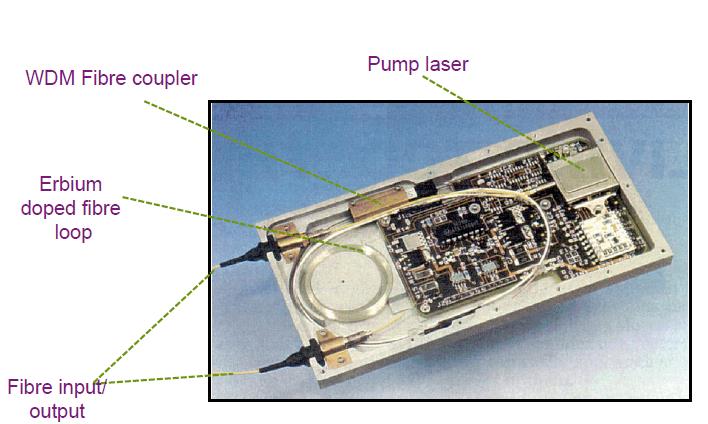
The main advantages and drawbacks of EDFAs are as follows.
Advantages
- Commercially available in C band (1,530 to 1,565 nm) and L band (1,560 to 1,605) and up to 84-nm range at the laboratory stage.
- Excellent coupling: The amplifier medium is an SM fiber;
- Insensitivity to light polarization state;
- Low sensitivity to temperature;
- High gain: > 30 dB with gain flatness < ±0.8 dB and < ±0.5 dB in C and L band, respectively, in the scientific literature and in the manufacturer documentation
- Low noise figure: 4.5 to 6 dB
- No distortion at high bit rates;
- Simultaneous amplification of wavelength division multiplexed signals;
- Immunity to crosstalk among wavelength multiplexed channels (to a large extent)
Drawbacks
- Pump laser necessary;
- Difficult to integrate with other components;
- Need to use a gain equalizer for multistage amplification;
- Dropping channels can give rise to errors in surviving channels:dynamic control of amplifiers is necessary.
A Lower Order-ODU or LO-ODU is an ODUk, whose OPUk transports a inside mapped client.
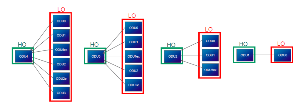
An Higher Order-ODU or HO-ODU is an ODUk, whose OPUk transports an inside multiplexed ODUj.
LO-ODU and HO-ODU have the same structure but with different clients.
The LO-ODU is either mapped into the associated OTUk or multiplexed into an HO-ODU.
The HO-ODU is mapped into the associated OTUk.
Please notice that, HO-ODUj multiplexed into HO-ODUk is an undesired hierarchy in one domain.
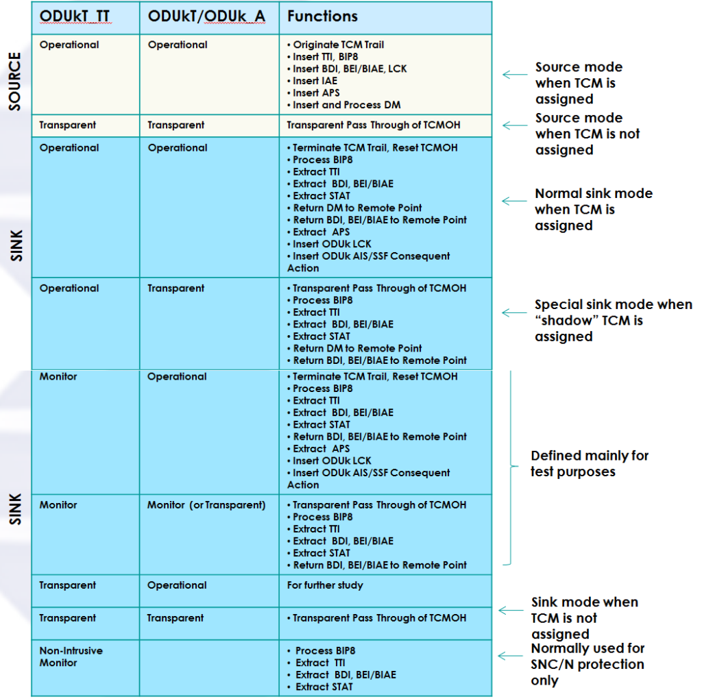
ODUkT_TT and ODUkT/ODUk_A TCM modes