Dispersion compensation-An Introduction
Fiber dispersion is one of the most critical parameters that need to be considered for high speed transmission design. Dispersion typically varies with wavelength and accumulates along a fiber length. Therefore it is difficult to precisely compensate for all the propagating channels with fixed optical compensation modules at the same time. When preferred, dispersion at each channel can be fully compensated electronically in the DSP of the receiver.
Dispersion compensation basically means eliminating the compounded dispersion originating from length of the fiber. There might be a misconception that having a fiber with zero dispersion would avoid such a drama. However this is not true as verified from older experience with dispersion-shifted fiber (DSF). A DSF is designed with zero dispersion between 1525 nm and 1575 nm. This would work perfectly for a single channel transmission inside this window. However in DWDM transmission, it gives rise to undesired levels Four Wave Mixing which renders DWDM transmission practically impossible. Therefore, the goal is not to reduce the dispersion to zero but to avoid excessive temporal broadening of the pulses so that the residual dispersion is still within the tolerable limits of the system.
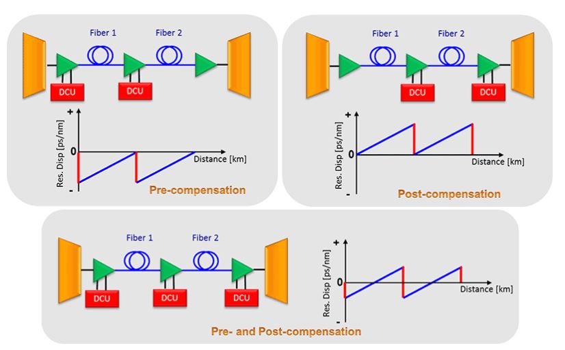
Several technologies exist for chromatic dispersion compensation, such as dispersion compensating fiber/ unit (DCF/U), dispersion managed cables, higher-order mode DCF, fiber Bragg gratings and optical phase conjugation. The widely used compensation is via the dispersion compensating fiber. In general, chromatic dispersion can be compensated in lump or according to dispersion map/management. In lump compensation, the accumulated dispersion is compensated in bulk using in-line dispersion compensation while with dispersion management the local dispersion evolution along the link is compensated utilizing the DCFs as shown in the figure.
Dispersion compensating fiber, as the name implies, is actually a fiber with large negative dispersion parameter that can be inserted into the link at regular intervals. The compensating fiber typically has a dispersion of -100 ps/nm/km in the 1550 nm region and thus only a short length of this fiber would be required to compensate the accumulated dispersion arising from hundreds of km of transmission fiber. However, insertion of DCF is not addition of new fiber or doesn’t increase transmission distance. The added length of fiber is placed as a bulk at one end of the link. This nevertheless adds attenuation and additional amplification may be needed to compensate and achieve the desired reach. A typical DCF attenuation is about 0.5 dB/km.
As mentioned before, in a DWDM system, it is quite difficult to balance dispersion characteristic over a range of wavelengths i.e. for all the co-propagating channels. When residual dispersion for center channel of the DWDM spectrum has been compensated to zero, other channels at extremes will have significant finite dispersion. The dispersion compensation is therefore optimized in such a way such that the finite dispersion in the neighboring channel is either less than the tolerable range or then compensated electronically.
original link:http://blog.cubeoptics.com/index.php/2014/06/dispersion-compensation
Unlock Premium Content
Join over 400K+ optical network professionals worldwide. Access premium courses, advanced engineering tools, and exclusive industry insights.
Already have an account? Log in here