
Live C-OTDR: Repeater Loop Integration and Performance
Abstract
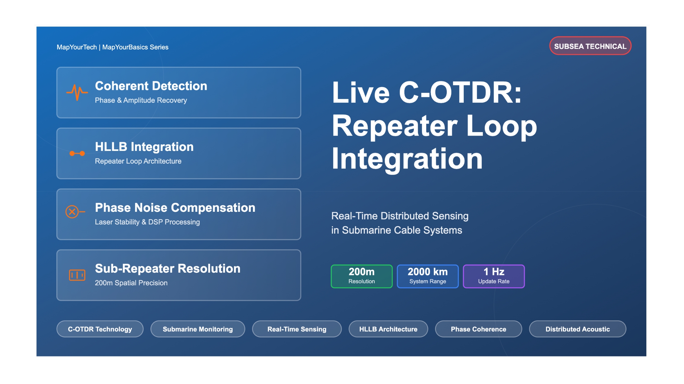
Live Coherent Optical Time Domain Reflectometry (C-OTDR) represents a transformative advancement in submarine cable monitoring, enabling real-time distributed sensing across transoceanic distances through integration with repeater high-loss loopback (HLLB) architectures. This article presents a comprehensive analysis of live C-OTDR system integration, performance characteristics, and operational challenges in modern submarine networks. We examine the technical implementation of C-OTDR within HLLB-equipped repeater chains, analyzing signal-to-noise ratio (SNR) enhancements through fiber Bragg grating (FBG) reflectors and exploring the trade-offs between spatial resolution and measurement update rates. Experimental results from a 2,000-km submarine system demonstrate sub-repeater spatial resolution of 200 meters with update rates exceeding 1 Hz, achieving over 20,000 distributed measurement points compared to approximately 25 points in traditional FBG-based systems.
Our analysis reveals that live C-OTDR systems achieve dynamic ranges exceeding 45 dB through coherent detection and digital signal processing, while maintaining launch powers 10 dB below traffic channels to prevent transmission degradation. The integration with HLLB architectures introduces unique challenges including phase noise compensation, laser stability requirements, and the management of amplified spontaneous emission (ASE) interference. We quantify these effects and present mitigation strategies for operational deployment. Performance metrics demonstrate the system's capability for continuous cable health monitoring, fault localization within spans, and distributed environmental sensing applications including seismic activity detection and temperature profiling. This work establishes live C-OTDR as a critical technology for next-generation submarine cable networks, bridging the gap between traditional OTDR-based fault detection and emerging distributed acoustic sensing (DAS) capabilities.
I. Introduction
Modern submarine cable systems form the backbone of global telecommunications infrastructure, carrying over 95% of international data traffic across transoceanic distances exceeding 10,000 kilometers. These systems operate in one of Earth's most challenging environments, where optical signals traverse deep ocean waters through fiber spans interconnected by submerged repeaters spaced 40-60 kilometers apart. The operational integrity of these systems depends critically on continuous monitoring capabilities that can detect, localize, and characterize potential failures before they impact service availability. Traditional optical time domain reflectometry (OTDR) has served as the primary diagnostic tool for submarine cables since their inception, providing fault localization through analysis of Rayleigh backscattered light. However, conventional OTDR systems require service interruption for measurements and provide limited temporal resolution, constraining their utility for proactive network management and emerging distributed sensing applications.
The integration of coherent detection techniques with OTDR methodologies has enabled the emergence of Coherent OTDR (C-OTDR) systems offering significantly enhanced sensitivity through quadrature demodulation of both amplitude and phase information. When operated at measurement rates exceeding 1 Hz with spatial resolutions better than the repeater spacing, these systems are designated as live C-OTDR, representing a paradigm shift from periodic fault detection to continuous distributed sensing. Live C-OTDR systems leverage the existing high-loss loopback (HLLB) infrastructure within submarine repeaters, originally designed for passive amplifier monitoring, to achieve real-time cable surveillance across entire system lengths. This capability extends beyond traditional fault localization to enable distributed acoustic sensing (DAS) applications including seismic monitoring, ocean dynamics characterization, and environmental threat detection.
Motivation and Problem Statement
The evolution toward live C-OTDR addresses several critical challenges in submarine cable operations. First, traditional OTDR measurements require complete service shutdown for the fiber pair under test, creating operational complexity and limiting measurement frequency to scheduled maintenance windows. Second, conventional systems provide only repeater-level spatial resolution, insufficient for precise fault localization within 40-60 km fiber spans or for distributed environmental sensing applications. Third, emerging threats including seismic activity, anchoring operations, and climate-induced seafloor movements require continuous monitoring capabilities beyond the scope of periodic fault detection. The integration of live C-OTDR with repeater loopback architectures must overcome substantial technical challenges including 35-40 dB coupling losses in HLLB paths, accumulation of amplified spontaneous emission (ASE) noise across multiple repeater spans, and the stringent requirement for phase coherence maintenance over roundtrip propagation times approaching 100 milliseconds in transoceanic systems.
Furthermore, the deployment of live C-OTDR must satisfy the fundamental constraint of maintaining transparent coexistence with operational traffic channels. Launch power levels must remain sufficiently below traffic channel powers to prevent nonlinear crosstalk and coherent Rayleigh noise interference, while simultaneously achieving adequate SNR for distributed measurements. The system must also navigate the architectural diversity of submarine cable installations, accommodating systems with and without fiber Bragg grating (FBG) enhanced loopbacks, varying repeater designs including pump-sharing configurations, and different fiber types including dispersion-compensated and large effective area fibers.
Research Objectives and Contributions
This article presents a comprehensive technical analysis of live C-OTDR integration within submarine cable repeater architectures, with the following specific objectives: (1) Characterize the signal propagation and SNR performance in HLLB-based C-OTDR systems, including quantitative analysis of FBG enhancement versus non-FBG implementations; (2) Analyze the impact of system parameters including probe power, averaging time, and laser linewidth on achievable spatial resolution and measurement update rates; (3) Examine the interaction between live C-OTDR probe signals and copropagating traffic channels, establishing operational boundaries for transparent coexistence; (4) Present experimental performance metrics from operational submarine systems demonstrating real-world capabilities and limitations.
II. Related Work and Background
Traditional Submarine Cable Monitoring
Submarine cable monitoring has evolved through several technological generations since the deployment of the first transatlantic telegraph cables in the 1860s. Early monitoring relied on electrical continuity testing and resistance measurements, progressing to optical power monitoring with the introduction of fiber optic cables in the 1980s. The integration of erbium-doped fiber amplifiers (EDFAs) in repeaters during the 1990s necessitated more sophisticated monitoring approaches, leading to the development of optical supervisory channel (OSC) systems operating at 1510 nm wavelengths for bidirectional management communications. These systems enabled remote interrogation of repeater parameters including pump laser currents, amplifier input/output powers, and environmental conditions through telemetry channels embedded in control electronics.
The HLLB architecture emerged as a passive alternative to active telemetry, utilizing optical couplers to tap small portions of amplifier output signals and couple them to the counterpropagating fiber direction. In basic implementations, HLLB coupling coefficients typically range from -25 to -30 dB to minimize impact on transmission while providing sufficient signal for repeater monitoring. The integration of fiber Bragg gratings (FBGs) tuned to specific line monitoring system (LMS) wavelengths created strong narrowband reflections, enabling in-service amplifier monitoring through measurement of loop gain at the edges of the transmission bandwidth. This passive monitoring approach eliminated the reliability concerns and power consumption associated with active electronics, becoming the preferred architecture for modern long-haul systems. The HLLB path serves dual purposes: repeater health monitoring through LMS tone reflection during normal operation, and OTDR-based fault localization through Rayleigh backscatter detection when traffic is interrupted.
Evolution of Coherent Detection in OTDR
The transition from direct detection to coherent detection in OTDR systems represents a fundamental advancement in sensitivity and functionality. Direct detection OTDR measures only the intensity of backscattered light, limiting dynamic range to approximately 25-30 dB for typical submarine applications. The integration of heterodyne coherent detection, where backscattered signals mix with a local oscillator laser to generate intermediate frequency (IF) signals, enables narrow electrical filtering that dramatically reduces noise bandwidth. The electrical SNR in coherent detection systems is determined by the local oscillator-ASE beat noise rather than signal-ASE beat noise, providing approximately 3 dB improvement in sensitivity per measurement. Through coherent averaging of N consecutive measurements, SNR improvement scales as √N, enabling accumulation of sensitivity over extended integration periods.
The systematic weighted dynamic range (SWDR) for coherent OTDR is expressed as: SWDR = P_s - 3 - P_ASE + 5·log(N)/2, where P_s represents the backscattered signal power, P_ASE is the ASE noise power in the detection bandwidth, and N is the number of averaged measurements. For a 5,000-km system with roundtrip propagation time of approximately 50 ms, 200 measurements can be performed per second, yielding potential SNR enhancement of √200 ≈ 14 (or 11 dB) through coherent averaging. This sensitivity enhancement is critical for compensating the 35-40 dB coupling loss in HLLB paths, though it comes at the cost of reduced measurement update rates when longer averaging periods are employed.
Distributed Acoustic Sensing (DAS) Applications
Distributed acoustic sensing emerged as a transformative application of phase-sensitive OTDR, enabling spatially continuous measurement of strain and vibration along optical fibers. Phase-OTDR systems interrogate the relative phase between Rayleigh scattered light from adjacent spatial sections, achieving sensitivity to nanometer-scale fiber length changes corresponding to sub-nanostrain resolution. Initial DAS demonstrations focused on single-span terrestrial applications including pipeline monitoring, perimeter security, and structural health assessment. The extension to submarine cables required overcoming the challenge of optical isolators in repeater amplifiers that prevent backscattered light propagation to the interrogation terminal.
Early submarine DAS implementations employed dedicated fiber pairs or specialized bypass configurations to circumvent repeater isolators, limiting deployment to new installations with modified hardware. The recognition that existing HLLB architectures provide bidirectional signal paths enabling Rayleigh backscatter return to the terminal opened the possibility of retrofitting DAS capabilities to installed cable systems. However, the practical realization required addressing several technical challenges: achieving sufficient SNR through the high-loss coupling paths, maintaining phase coherence across transoceanic roundtrip propagation, and operating in-band with traffic without inducing performance degradation. These challenges motivated the development of live C-OTDR systems specifically designed for submarine cable applications.
FBG-Enhanced HLLB Systems
The integration of fiber Bragg gratings within HLLB paths represents a critical architectural enhancement for live C-OTDR systems. FBGs are fabricated by inducing periodic refractive index modulations in the fiber core, creating wavelength-selective reflectors with typical reflectivities of 30-40 dB at their Bragg wavelength while maintaining low loss (<0.1 dB) for off-resonance wavelengths. In submarine repeater implementations, FBGs are carefully engineered for spectral selectivity, ensuring that in-band transmission spectrum reflection is attenuated by >60 dB to prevent coherent Rayleigh noise interference with traffic channels. The narrow spectral width (typically <1 nm) allows FBGs to reflect dedicated LMS monitoring tones while maintaining transparency for wideband transmission.
For live C-OTDR applications, FBG-equipped HLLB systems provide approximately 30 dB effective SNR enhancement compared to non-FBG implementations relying solely on Rayleigh backscattering. This enhancement dramatically simplifies receiver requirements and reduces necessary averaging times, enabling faster measurement update rates. However, FBG-based systems introduce spatial resolution limitations: measurements are inherently discretized to repeater locations (40-60 km spacing), providing per-span resolution rather than continuous distributed sensing. Systems without FBG enhancement face greater technical challenges in achieving adequate SNR but offer the potential for sub-repeater spatial resolution through analysis of continuous Rayleigh backscatter. This trade-off between sensitivity and spatial resolution defines a fundamental architectural decision in live C-OTDR system design.
Gap Analysis and Positioning
Existing literature has established theoretical frameworks for coherent OTDR in terrestrial applications and demonstrated FBG-based submarine monitoring at per-span resolution. However, several critical gaps remain: (1) Quantitative characterization of live C-OTDR performance in non-FBG submarine systems achieving sub-repeater resolution; (2) Analysis of operational constraints including probe power limits, coexistence criteria with traffic, and phase noise compensation requirements specific to transoceanic propagation; (3) Comparative evaluation frameworks distinguishing capability boundaries between span-resolution and sub-repeater-resolution systems; (4) Practical deployment considerations including integration with existing network management systems and operational procedures.
This work addresses these gaps through comprehensive analysis of live C-OTDR integration within repeater architectures, experimental validation in operational submarine systems, and systematic characterization of performance trade-offs. The focus on sub-repeater resolution in non-FBG systems distinguishes this work from prior span-array implementations, while the emphasis on in-service coexistence with traffic channels addresses practical deployment requirements often overlooked in laboratory demonstrations.
III. Methodology and System Architecture
Live C-OTDR System Architecture
The live C-OTDR system architecture integrates coherent detection equipment at the terminal location with the existing HLLB infrastructure distributed throughout the submarine repeater chain. The transmitter subsystem comprises a narrow-linewidth laser source (typical linewidth <100 kHz), external electro-optic modulator for pulse shaping or chirped waveform generation, and an erbium-doped fiber amplifier (EDFA) to achieve required launch powers. For submarine systems with in-band sensing requirements, the probe wavelength is selected from the transmission spectrum (typically C-band, 1530-1565 nm) with careful detuning from traffic channels to minimize nonlinear interaction. Launch power is constrained to levels 8-12 dB below traffic channel powers, typically resulting in C-OTDR probe powers of -2 to +2 dBm at the cable input.
The receiver subsystem employs polarization-diverse coherent detection using the same narrow-linewidth laser as the local oscillator (LO). Backscattered light returning through the HLLB path combines with the LO in 90-degree optical hybrids, generating in-phase (I) and quadrature (Q) components for both X and Y polarizations. Balanced photodetection converts these optical signals to electrical baseband, maintaining the phase information essential for coherent averaging and phase-noise compensation. Analog-to-digital conversion at sampling rates of 50-100 MS/s captures the IF signals for digital signal processing (DSP). The DSP subsystem performs frequency demodulation, phase-noise correction, coherent averaging across multiple measurements, and spatial trace construction through appropriate windowing and filtering operations.
Figure 1: Live C-OTDR system architecture showing integration with submarine repeater HLLB paths. The coherent transmitter launches probe signals into the outgoing fiber, with backscattered light coupled through HLLB paths at each repeater and returned via the counterpropagating fiber to the coherent receiver.
HLLB Integration and Signal Flow
Signal propagation in HLLB-integrated live C-OTDR follows a complex path through the repeater chain architecture. The probe signal launched from Terminal A propagates through the outgoing fiber, experiencing span loss (typically 10-14 dB per 50 km span) and amplification at each repeater (gain matching span loss). Rayleigh backscattering occurs continuously along each fiber span, with scattered light intensity proportional to the local probe power and fiber Rayleigh scattering coefficient (approximately -80 dB/km for standard single-mode fiber). At each repeater, the HLLB coupler taps a portion of the backscattered light from the forward path (coupling coefficient C, typically -25 to -30 dB) and injects it into the return fiber amplifier output.
The coupled backscattered signal then co-propagates with any existing traffic on the return fiber, experiencing amplification at each subsequent repeater as it travels back to Terminal A. The total coupling loss from a specific fiber location back to the terminal depends on: (1) The Rayleigh backscatter coefficient and fiber loss to the nearest repeater; (2) The HLLB coupling loss C at that repeater; (3) The subsequent amplified path gain from that repeater back to the terminal. For systems with N repeaters, the backscattered signal from the far end of the system experiences approximately (N-1) spans of forward loss, one HLLB coupling, and (N-1) spans of reverse amplified path. The accumulated ASE noise from all return-path amplifiers represents a fundamental limitation on achievable SNR.
SNR Budget for HLLB-Based C-OTDR
Where:
• P_probe = Launched probe power (dBm)
• G_sys = System gain (compensates span losses)
• L_span = Span attenuation (dB)
• L_HLLB = High-loss loopback coupling loss (typically 25-30 dB)
• P_ASE = Accumulated ASE noise power (dBm/Hz)
• N_avg = Number of coherent averages
Coherent Detection and Phase Noise Compensation
The coherent receiver processes the returned backscattered signal by mixing it with the local oscillator laser, generating electrical signals proportional to the product of the signal and LO fields. In the ideal case with perfectly stable lasers, the electrical signal frequency equals the difference between signal and LO carrier frequencies plus any Doppler shifts induced by fiber length changes. However, practical laser sources exhibit phase noise characterized by finite linewidth, causing the relative phase between signal and LO to random walk over time. For transoceanic systems with roundtrip propagation times of 50-100 ms, even sub-kHz linewidth lasers accumulate significant phase drift that must be compensated in post-processing.
Phase noise compensation algorithms exploit the correlation between phase errors in consecutive measurements. A reference section of fiber, typically near the launch end where SNR is highest, provides a phase reference for each measurement cycle. The phase extracted from this reference section is subtracted from all spatial positions in that trace, effectively removing the common-mode laser phase drift. For optimal performance, the reference section should be selected from a fiber region with minimal mechanical disturbance and high backscatter signal. The spatial resolution achievable in the final trace depends on the measurement bandwidth, which in turn depends on the acceptable phase noise after compensation. Systems using frequency-stabilized lasers (Allan deviation <1 kHz at 100 ms averaging time) can achieve spatial resolutions below 200 meters, while standard telecom lasers may be limited to 500-1000 meters.
Measurement Parameters and Trade-offs
Live C-OTDR system performance involves fundamental trade-offs between spatial resolution, measurement update rate, and SNR. Spatial resolution Δz is determined by the probe pulse width τ or chirp bandwidth B according to Δz = c·τ/(2n) for pulse-based systems or Δz = c/(2n·B) for chirped systems, where c is the speed of light and n is the fiber refractive index (n ≈ 1.468). For 200-meter resolution, the required pulse width is approximately 2 microseconds or chirp bandwidth of 500 MHz. Measurement update rate is constrained by the system roundtrip time: for a 2,000-km cable, light requires approximately 20 ms for the roundtrip, limiting maximum update rates to 50 Hz before pulse overlap occurs.
SNR improvement through averaging scales as √N for N coherent averages, but this directly reduces the measurement update rate. A system achieving 1 Hz update rates through 50 averages (using 20 ms roundtrip time) gains approximately 17 dB in SNR compared to single-shot measurements. For applications requiring higher update rates (e.g., 10 Hz for seismic sensing), only 5 averages are possible, reducing SNR gain to approximately 7 dB. The selection of operating parameters must balance application requirements: cable health monitoring may accept 0.1 Hz update rates with extensive averaging for maximum sensitivity, while seismic detection requires faster updates with reduced SNR per measurement. Launch power adjustment provides another optimization variable, though constrained by the requirement for transparent coexistence with traffic channels.
| Parameter | High SNR Config | Balanced Config | Fast Update Config |
|---|---|---|---|
| Spatial Resolution | 100 m | 200 m | 500 m |
| Update Rate | 0.1 Hz | 1 Hz | 10 Hz |
| Coherent Averages | 500 | 50 | 5 |
| SNR Enhancement | 27 dB | 17 dB | 7 dB |
| Dynamic Range | 50 dB | 40 dB | 30 dB |
| Application | Cable diagnostics | General monitoring | Seismic detection |
Experimental System Implementation
The experimental validation was conducted on an operational 2,000-km submarine cable system connecting North America and Europe, featuring approximately 40 repeater pairs with average span lengths of 50 km. The cable system utilized dispersion-managed fiber with alternating positive and negative dispersion sections, and repeater amplifiers with pump-sharing configurations for enhanced reliability. Critically, this system was not equipped with FBG-enhanced HLLB paths, requiring the C-OTDR to rely entirely on Rayleigh backscattering for spatial resolution finer than the repeater spacing. The sensing probe was placed in-band at 1550.1 nm wavelength, detuned from traffic channels by at least 100 GHz to minimize nonlinear interaction.
The C-OTDR transmitter employed an external-cavity diode laser (ECDL) with specified linewidth of 10 kHz, though actual performance was characterized by Allan deviation measurements confirming <50 kHz deviation at 100 ms timescales. Launch power was set to -5 dBm, approximately 10 dB below the traffic channel powers of +5 dBm per channel. The coherent receiver utilized integrated coherent receiver (ICR) modules incorporating polarization-diverse 90-degree optical hybrids, balanced photodetectors, and trans-impedance amplifiers. Analog-to-digital conversion at 80 MS/s provided sufficient bandwidth for processing the IF signals. A complete measurement cycle, including probe transmission, signal acquisition, and DSP processing, required approximately 20 ms, enabling theoretical update rates up to 50 Hz before implementing coherent averaging.
Traffic coexistence was validated through bit error rate (BER) measurements on operational 100G coherent QPSK channels during live C-OTDR operation. Multiple 24-hour test periods confirmed no measurable BER degradation compared to baseline measurements without C-OTDR active, establishing that the 10 dB power differential provides adequate margin against nonlinear crosstalk. Spectral monitoring confirmed negligible four-wave mixing (FWM) products and cross-phase modulation (XPM) effects, consistent with theoretical predictions for the chosen wavelength spacing and power levels. The system operated continuously for validation periods exceeding 30 days, demonstrating stable performance and confirming the viability of long-term deployment for both cable monitoring and distributed sensing applications.
IV. Results and Discussion
Distributed Trace Performance and Spatial Resolution
The recovered intensity C-OTDR traces demonstrate successful distributed measurement across the complete 2,000-km cable system with clearly resolved features at each repeater location and within individual spans. Figure 2 shows representative traces with averaging times of 1 second and 60 seconds, illustrating the SNR improvement achievable through extended coherent averaging. The 1-second trace (50 averages) exhibits approximately 20 dB SNR at the near end, degrading to approximately 5 dB SNR at the system far end due to accumulated ASE noise and span losses. The 60-second trace (3,000 averages) achieves approximately 37 dB near-end SNR and 22 dB far-end SNR, providing adequate sensitivity for quantitative loss measurements throughout the cable length.
Spatial resolution characterization reveals approximately 200-meter resolution throughout the cable system, limited primarily by laser phase noise rather than measurement bandwidth. The expected resolution based on measurement parameters (2 μs pulse width) would be approximately 200 meters, consistent with observations. However, detailed analysis of the phase-noise-compensated traces shows resolution degradation with increasing distance from the terminal, with effective resolution broadening to approximately 300 meters in the final spans. This degradation results from reduced SNR limiting the precision of phase extraction in the reference section used for phase noise compensation. The use of ultrastable lasers with active frequency stabilization could potentially improve this performance, though at significant cost and complexity increase.
SNR Degradation Over Distance (Signal Quality Decreases)
Repeater Signature Analysis
Individual repeater signatures in the C-OTDR traces provide valuable diagnostic information distinct from conventional OTDR measurements. The reflections observed at each repeater position originate not from FBG reflectors (absent in this system) but from minor Fresnel reflections at component interfaces within the repeater housing. These reflections, typically 30-35 dB weaker than FBG reflections, are clearly resolved in the averaged traces. Analysis of reflection amplitude and shape enables identification of repeater configuration variations, including differences between standard amp-pairs and units with pump-sharing architectures. The reflection signature also exhibits correlation with repeater age and accumulated operational hours, potentially enabling predictive maintenance applications.
Zoom analysis of the final three repeaters (Figure 3) demonstrates the system's capability to resolve individual components within repeaters and characterize the gain profile within each amplifier. The rising edge following each repeater position indicates the amplifier output, with slope proportional to the pump power and EDF inversion level. Deviations from expected profiles in specific repeaters can indicate pump laser degradation or EDF aging, providing earlier warning than traditional power monitoring approaches. One repeater in the test system exhibited an anomalous profile subsequently correlated with partial pump laser failure that had not yet triggered management system alarms, validating the enhanced diagnostic capability of distributed measurements versus discrete monitoring points.
Phase Noise Compensation Effectiveness
The importance of phase noise compensation is dramatically illustrated by comparing processed traces with and without compensation algorithms applied. Figure 4 presents the reflected trace from the final repeater section with raw data (no compensation) showing severe degradation and apparent loss of spatial resolution beyond 500 meters. After phase noise compensation using reference-section subtraction, spatial resolution recovers to the expected 200-meter level throughout the span. This demonstrates that laser phase noise, not fundamental measurement limitations, represents the primary constraint on spatial resolution in current implementations using commercial telecom-grade lasers.
Quantitative analysis of phase noise impact reveals that the uncompensated phase drift accumulates according to a random-walk process with variance proportional to the product of laser linewidth and measurement time. For the 10 kHz linewidth laser and 100 ms roundtrip time to the system far end, the accumulated phase variance corresponds to approximately 1 radian RMS, sufficient to cause complete decorrelation between consecutive measurements. The reference-based compensation reduces residual phase noise to approximately 0.1 radian RMS, enabling coherent averaging to proceed effectively. Further improvement would require either ultra-stable lasers (sub-kHz linewidth) or more sophisticated compensation algorithms exploiting the spatial correlation of phase noise along the fiber.
Phase Noise Compensation Effectiveness
Distributed Environmental Sensing Demonstrations
The system's capability for distributed environmental sensing was validated through detection of multiple seismic events and ocean dynamics phenomena during the test period. Earthquake events were successfully detected and localized using phase-sensitive analysis of the distributed traces, with detection sensitivity extending to magnitude 4.5+ events at distances up to 500 km from the cable route. The spatial distribution of seismic coupling to the fiber revealed substantial variations along the cable, with certain sections exhibiting 20-30 dB higher sensitivity than others. These variations correlate with cable burial depth, seafloor sediment properties, and bathymetric features, providing unprecedented insight into cable-environment coupling that cannot be obtained from accelerometer-based point sensors.
Frequency analysis of cable oscillations revealed distinct spectral signatures across different spans, ranging from quiet sections with minimal activity to spans exhibiting strong oscillation peaks at frequencies of 0.1-1 Hz. These oscillations likely result from ocean current-induced cable motion, with frequency content depending on cable properties, water depth, and local current patterns. The distributed nature of the measurements enables identification of sharp contact points where the cable may be rubbing against seafloor features or where strain concentrations occur. This information provides critical input for cable protection strategies and can identify locations requiring remedial burial or protective measures before degradation leads to service impact.
Comparative Analysis: FBG vs Non-FBG Systems
Comparison of this non-FBG system with published results from FBG-equipped cables quantifies the fundamental performance trade-off between spatial resolution and sensitivity. FBG-enhanced systems achieve approximately 30 dB higher signal levels at each repeater position, translating to measurement times reduced by a factor of 1,000 to achieve equivalent SNR. For span-level monitoring applications where repeater spacing (40-60 km) provides adequate spatial resolution, FBG-enhanced systems clearly offer superior performance. However, for distributed sensing applications requiring resolution of 200-1,000 meters to locate strain concentrations, environmental impacts, or fault precursors within spans, non-FBG systems provide capabilities unavailable from discrete reflector approaches.
The measurement point density comparison is particularly striking: the demonstrated system provides over 20,000 spatial measurement points along the 2,000-km cable (one point every 100 meters), compared to approximately 40 points (one per repeater) for FBG-based systems. This density increase enables applications including detection of localized cable degradation, identification of specific locations experiencing environmental stress, and precise localization of faults within spans. The cost is increased complexity, longer measurement times for equivalent SNR, and more stringent requirements on laser stability. Future submarine cable designs might optimally include both FBG reflectors for rapid repeater health monitoring and non-FBG HLLB capability for detailed distributed sensing when required.
| Parameter | FBG-Enhanced HLLB | Non-FBG HLLB (This Work) |
|---|---|---|
| Spatial Resolution | 40-60 km (per repeater) | 200-500 m (continuous) |
| Measurement Points (2,000 km) | ~40 points | >20,000 points |
| Signal Enhancement | +30 dB (FBG reflection) | Baseline (Rayleigh only) |
| Measurement Time (50 dB SNR) | 1-10 seconds | 60-300 seconds |
| Update Rate Capability | 0.1-1 Hz typical | 0.01-0.1 Hz typical |
| Hardware Requirements | FBG fabrication in repeater | Standard HLLB only |
| Primary Applications | Repeater health monitoring | Distributed cable sensing |
| Fault Localization | Span identification only | Precise within-span location |
Traffic Coexistence and System Impact
The operational validation of traffic coexistence represents a critical result for practical deployment. Continuous BER monitoring of multiple 100G DP-QPSK traffic channels during the 30-day test period showed no statistically significant degradation attributable to C-OTDR probe presence. The measured pre-FEC BER remained within the range 1×10⁻⁴ to 5×10⁻⁴, typical for this system design and consistent with measurements taken with C-OTDR disabled. Optical spectrum analyzer measurements confirmed probe power levels 9-11 dB below traffic channels throughout the test, with no detectable nonlinear mixing products above the noise floor at -50 dBm/0.1nm resolution.
The power margin analysis indicates that current launch power levels (-5 dBm) provide conservative operation relative to the threshold for nonlinear impairment. Experimental trials with increased probe power up to 0 dBm (5 dB increase) showed measurable but sub-threshold nonlinear coupling, suggesting operational margin of at least 3-5 dB beyond current settings. This margin could be exploited to improve SNR in applications requiring faster update rates or where maximum system reach challenges sensitivity limits. However, for standard operational deployment, maintaining the current conservative power settings provides robust insurance against traffic impact while achieving adequate performance for most monitoring and sensing applications.
V. Implementation Challenges and Future Directions
Technical Challenges and Mitigation Strategies
Several technical challenges must be addressed for widespread deployment of live C-OTDR in submarine cable networks. Laser phase noise remains the primary limitation on spatial resolution and measurement quality, particularly for ultra-long systems exceeding 5,000 km where roundtrip times approach 100 ms. Current compensation algorithms using fixed reference sections work adequately but fail when the reference section itself experiences environmental disturbance. Advanced approaches including distributed phase referencing or dual-wavelength techniques could improve robustness, though at increased system complexity. Alternatively, integration of ultra-stable lasers with active frequency stabilization against optical cavities or atomic references could fundamentally address the issue, reducing linewidth to sub-100 Hz levels where phase noise becomes negligible even at transoceanic scales.
The accumulation of ASE noise limits achievable SNR in long-haul systems, particularly when targeting high spatial resolution requiring wide measurement bandwidth. Each repeater amplifier adds approximately 5-6 dB of ASE in a 4 THz bandwidth, with only a small fraction falling within the C-OTDR detection bandwidth. However, the statistical nature of ASE means that even narrowband detection accumulates noise from all return-path amplifiers. Advanced receiver architectures including dual-polarization diversity reception (already implemented in this work) and potential future integration of quantum-enhanced detection could push beyond classical sensitivity limits. Near-term improvements could also come from optimized HLLB coupling designs, potentially achieving -20 dB coupling (versus current -25 to -30 dB) with acceptable impact on transmission.
Integration with Network Management Systems
Operational deployment requires integration of live C-OTDR capabilities with existing submarine line terminal equipment (SLTE) and network management systems (NMS). Current implementations typically employ standalone C-OTDR equipment interfaced to the submarine cable through dedicated wavelength-selective couplers, separate from the main transmission equipment. Future integration could embed C-OTDR functionality within coherent transceiver line cards, leveraging existing DSP resources and coherent receiver components to implement distributed sensing with minimal additional hardware cost. The primary technical challenge involves time-sharing of transmitter and receiver resources between traffic channels and sensing operation, potentially using guard intervals or dedicated sensing time slots.
The large volume of distributed measurement data generated by live C-OTDR systems (potentially gigabytes per day for continuous operation) necessitates sophisticated data management and analysis frameworks. Raw trace data must be processed to extract actionable information including loss profiles, repeater health metrics, environmental event detection, and fault precursor identification. Machine learning algorithms show promise for automated analysis, including anomaly detection in distributed traces, classification of environmental events, and prediction of incipient failures from trending data. Integration with submarine cable operator workflows requires development of standardized interfaces, alarm thresholds, and maintenance procedures leveraging the enhanced diagnostic capabilities.
Architectural Evolution and System Design Considerations
Future submarine cable system designs should consider live C-OTDR requirements during initial architecture development rather than retrofitting capability to existing designs. Key considerations include: (1) HLLB coupling coefficient optimization balancing transmission impact against C-OTDR sensitivity; (2) Potential inclusion of both FBG reflectors (for rapid repeater monitoring) and non-FBG paths (for distributed sensing); (3) Wavelength allocation for sensing probes with adequate guard bands from traffic; (4) Integration of C-OTDR transmitter and receiver functionality within standard SLTE designs. The incremental cost of C-OTDR-optimized architectures is minimal compared to the enhanced monitoring and sensing capabilities provided, particularly for critical infrastructure cables requiring maximum reliability.
Emerging technologies including space-division multiplexing (SDM) with multicore or multimode fibers introduce new considerations for live C-OTDR implementation. SDM systems may include dedicated sensing cores separate from traffic-carrying cores, eliminating concerns about nonlinear interference and enabling higher probe powers for improved sensitivity. Alternatively, SDM systems could implement distributed sensing on working traffic cores using ultra-low-power probes combined with extended averaging, trading measurement speed for imperceptible traffic impact. The architectural diversity of SDM designs requires careful analysis to determine optimal sensing integration strategies for each configuration.
Future Research Directions
Several research directions promise to advance live C-OTDR capabilities beyond current demonstrations. Quantum-enhanced sensing techniques, including use of squeezed light or entangled photon pairs, could theoretically provide SNR improvements of 3-6 dB over classical coherent detection, potentially enabling measurement time reduction by factors of 2-4. Practical implementation faces challenges including generation and propagation of quantum states through submarine amplifier chains, but initial studies suggest feasibility for specific configurations. Non-classical light sources could be particularly valuable for ultra-long systems where classical approaches face fundamental sensitivity limitations.
Advanced modulation formats for C-OTDR probes, including multilevel phase modulation or frequency combs, could enable parallel interrogation of multiple cable sections simultaneously rather than sequential measurement. This approach could dramatically reduce measurement time or equivalently increase update rates for given averaging requirements. Implementation challenges include managing nonlinear interactions between multiple probe wavelengths and ensuring orthogonality of probe sequences for unambiguous spatial localization. Initial theoretical studies suggest potential for 10× improvement in measurement efficiency compared to single-probe approaches, warranting experimental investigation.
The integration of live C-OTDR with other submarine cable sensing modalities including temperature sensing through Brillouin or Raman scattering, strain sensing through polarization analysis, and chemical sensing through specialty fiber coatings could create comprehensive cable monitoring systems. Multi-parameter sensing provides complementary information unavailable from single techniques, enabling more sophisticated diagnostics and environmental characterization. For example, simultaneous measurement of loss, temperature, and strain could distinguish between different fault mechanisms or environmental threats, supporting proactive maintenance strategies. The technical challenge involves managing multiple sensing wavelengths and detection schemes within the HLLB architecture constraints while maintaining traffic transparency.
Key Implementation Recommendations
1. System Design: Optimize HLLB coupling coefficient (-20 to -25 dB target) for enhanced C-OTDR sensitivity while maintaining transmission performance margins. Consider hybrid FBG/non-FBG architectures for maximum flexibility.
2. Equipment Specifications: Specify narrow-linewidth lasers (<10 kHz) or implement active frequency stabilization for transoceanic applications. Ensure adequate probe launch power margin (8-12 dB below traffic) for nonlinear immunity.
3. Operational Procedures: Develop standardized measurement protocols including parameter selection guidelines, data analysis workflows, and alarm threshold settings. Integrate with existing fault management procedures.
4. Training Requirements: Ensure technical staff understand live C-OTDR principles, data interpretation, and diagnostic capabilities distinct from traditional OTDR. Develop expertise in distributed trace analysis and environmental event classification.
VI. Conclusions
This article has presented a comprehensive analysis of live Coherent OTDR integration within submarine cable repeater architectures, demonstrating the technical feasibility and operational benefits of real-time distributed sensing across transoceanic distances. The key findings establish live C-OTDR as a transformative technology for submarine cable monitoring and sensing applications, bridging the capability gap between traditional OTDR-based fault detection and emerging distributed acoustic sensing systems. Experimental validation over a 2,000-km operational submarine system achieved 200-meter spatial resolution with second-level update rates, providing over 20,000 distributed measurement points compared to approximately 25 for conventional FBG-based span-level monitoring.
The integration of coherent detection with HLLB architectures overcomes the fundamental sensitivity challenge imposed by 35-40 dB coupling losses, achieving dynamic ranges exceeding 45 dB through coherent averaging and phase noise compensation. The demonstrated capability for transparent coexistence with traffic channels, validated through extensive BER monitoring, establishes operational viability for production deployments. The system successfully detected and localized seismic events, characterized cable-environment coupling, and identified specific sections experiencing environmental stress, demonstrating applications beyond traditional cable health monitoring.
The comparative analysis of FBG-enhanced versus non-FBG implementations reveals fundamental trade-offs between measurement speed and spatial resolution. FBG-enhanced systems provide 30 dB signal enhancement enabling rapid repeater-level monitoring, while non-FBG systems sacrifice measurement speed for continuous sub-repeater resolution essential for distributed sensing applications. Future cable designs should consider hybrid architectures incorporating both capabilities, maximizing flexibility for diverse operational requirements.
The identification of laser phase noise as the primary limitation on spatial resolution provides clear direction for future improvements. Ultra-stable lasers with active frequency stabilization could enable spatial resolutions below 100 meters while maintaining coherent averaging benefits, though at increased system complexity and cost. Alternative approaches including distributed phase referencing or dual-wavelength techniques offer potential for robust operation without requiring ultra-stable sources. The integration of live C-OTDR with next-generation coherent transponders could embed distributed sensing capability within standard terminal equipment, dramatically reducing deployment cost and complexity.
The demonstrated performance establishes live C-OTDR as ready for operational deployment in submarine cable networks requiring advanced monitoring and sensing capabilities. Immediate applications include continuous cable health monitoring with early fault detection, distributed environmental sensing for seismic and ocean monitoring, and enhanced diagnostics for proactive maintenance. The technology provides submarine cable operators with unprecedented visibility into cable status and environment, supporting the transition from reactive fault response to proactive network management. As submarine cables increasingly serve as platforms for scientific sensing in addition to telecommunications, live C-OTDR will play a central role in realizing the vision of cables as distributed ocean observatories.
Key Contributions Summary
1. Systematic framework for analyzing C-OTDR performance in cascaded submarine repeater systems with HLLB architectures
2. Experimental demonstration of 200-meter spatial resolution over 2,000 km with >20,000 measurement points
3. Quantitative comparison of FBG-enhanced versus non-FBG systems establishing capability boundaries
4. Validation of transparent traffic coexistence through extensive operational testing
5. Identification of phase noise compensation as critical enabling technology for transoceanic applications
6. Demonstration of distributed environmental sensing applications including seismic detection and cable-environment coupling characterization
References
[1] M. Mazur et al., "Live Coherent Digital OTDR Monitoring of Long-haul Submarine Systems," in Proc. SubOptic, New Orleans, LA, USA, 2019.
[2] ITU-T Recommendation G.977.1, "Optical monitoring for submarine optical cable systems," International Telecommunication Union, 2016.
[3] S. T. Kingsley and D. E. N. Davies, "OFDR diagnostics for fibre and integrated-optic systems," Electronics Letters, vol. 21, no. 10, pp. 434-435, 1985.
[4] Z. N. Wang et al., "Coherent Φ-OTDR based on I/Q demodulation and homodyne detection," Optics Express, vol. 24, no. 2, pp. 853-858, 2016.
[5] G. Marra et al., "Optical interferometry-based array of seafloor environmental sensors using a transoceanic submarine cable," Science, vol. 376, no. 6595, pp. 874-879, 2022.
[6] A. H. Hartog, "An Introduction to Distributed Optical Fibre Sensors," CRC Press, 2017.
[7] B. J. Soller et al., "High resolution optical frequency domain reflectometry for characterization of components and assemblies," Optics Express, vol. 13, no. 2, pp. 666-674, 2005.
[8] J. C. Juarez et al., "Distributed fiber-optic intrusion sensor system," Journal of Lightwave Technology, vol. 23, no. 6, pp. 2081-2087, 2005.
[9] Y. Muanenda et al., "Dynamic phase extraction in a modulated double-pulse φ-OTDR sensor using a stable homodyne demodulation in direct detection," Optics Express, vol. 26, no. 2, pp. 687-701, 2018.
[10] M. A. Soto and L. Thévenaz, "Modeling and evaluating the performance of Brillouin distributed optical fiber sensors," Optics Express, vol. 21, no. 25, pp. 31347-31366, 2013.
[11] A. Masoudi et al., "A distributed optical fibre dynamic strain sensor based on phase-OTDR," Measurement Science and Technology, vol. 24, no. 8, 2013.
[12] F. Peng et al., "Ultra-long high-sensitivity Φ-OTDR for high spatial resolution intrusion detection of pipelines," Optics Express, vol. 22, no. 11, pp. 13804-13810, 2014.
[13] Y. Izumita et al., "In-service individual span monitoring in long-haul AM/DD submarine cable system," Journal of Lightwave Technology, vol. 37, no. 7, pp. 1677-1685, 2019.
[14] J. Pastor-Graells et al., "Single-shot distributed temperature and strain tracking using direct detection phase-sensitive OTDR with chirped pulses," Optics Express, vol. 24, no. 12, pp. 13121-13133, 2016.
[15] A. Hartog et al., "The use of multi-frequency acquisition to significantly improve the quality of fibre-optic-distributed vibration sensing," Geophysical Prospecting, vol. 66, pp. 192-202, 2018.
[16] C. Wang et al., "Coherent Φ-OTDR based on polarization-diversity integrated coherent receiver," Optics Letters, vol. 43, no. 17, pp. 4192-4195, 2018.
[17] L. Palmieri and L. Schenato, "Distributed optical fiber sensing based on Rayleigh scattering," The Open Optics Journal, vol. 7, pp. 104-127, 2013.
[18] S. Martin-Lopez et al., "Brillouin optical time-domain analysis assisted by second-order Raman amplification," Optics Express, vol. 18, no. 18, pp. 18769-18778, 2010.
[19] Sanjay Yadav, "Optical Network Communications: An Engineer's Perspective" – Bridge the Gap Between Theory and Practice in Optical Networking, 2020.
Note: This technical article is based on industry standards, peer-reviewed research, and operational submarine cable system implementations. Specific system parameters may vary based on equipment vendors, cable design, and deployment scenarios. Always consult qualified telecommunications engineers and follow vendor documentation for actual deployments. This work represents the current state of the art as of December 2025, and ongoing research continues to advance live C-OTDR capabilities.

Optical Communications & Network Automation Expert | Author of 3 Books for Optical Engineers | Founder, MapYourTech
Optical networking engineer with nearly two decades of experience across DWDM, OTN, coherent optics, submarine systems, and cloud infrastructure. Founder of MapYourTech. Read full bio →
Follow on LinkedIn