

Generic selectors
Exact matches only
Search in title
Search in content
Post Type Selectors
Articles
lp_course
lp_lesson
Back
HomeAnalysisA Comprehensive Professional Guide to Understanding, Measuring, and Mitigating Optical Noise in Fiber Communication Systems
A Comprehensive Professional Guide to Understanding, Measuring, and Mitigating Optical Noise in Fiber Communication Systems

A Comprehensive Professional Guide to Understanding, Measuring, and Mitigating Optical Noise in Fiber Communication Systems

Last Updated: April 2, 2026
32 min read
155
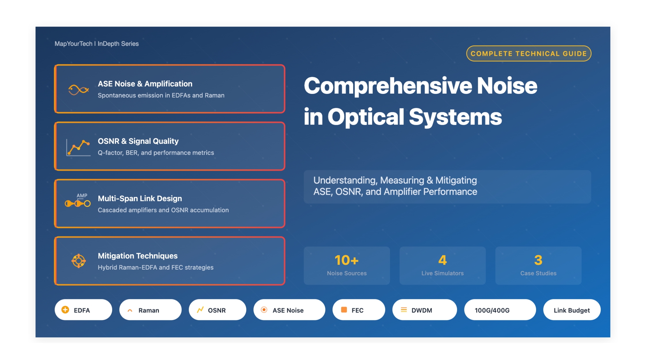
Noise in Optical Systems - Complete Guide
A Comprehensive Professional Guide to Understanding, Measuring, and Mitigating Optical Noise in Fiber Communication Systems - Image 1

Noise in Optical Systems

A Comprehensive Professional Guide to Understanding, Measuring, and Mitigating Optical Noise in Fiber Communication Systems

Fundamentals & Core Concepts

What is Noise in Optical Systems?

Noise in optical systems refers to unwanted random fluctuations in optical power that degrade the quality of transmitted signals in fiber optic communication networks. These random variations interfere with the desired optical signal, reducing the system's ability to accurately detect and decode the transmitted information.

Key Definition: Optical noise represents the ratio of signal power to noise power within a specified bandwidth, typically measured as Optical Signal-to-Noise Ratio (OSNR). OSNR is expressed in decibels (dB) and directly correlates with the Bit Error Rate (BER) and overall system performance.

Why Does Optical Noise Occur?

Optical noise originates from fundamental physical processes and system components:

  • Quantum Nature of Light: Photons are discrete particles, and their emission and detection are inherently probabilistic processes governed by quantum mechanics
  • Spontaneous Emission: In optical amplifiers, excited atoms spontaneously emit photons in random directions with random phases, creating Amplified Spontaneous Emission (ASE)
  • Thermal Activity: Temperature-induced random electron motion in receivers generates thermal noise
  • Nonlinear Effects: High-power signals interacting with fiber material properties create noise through phenomena like Stimulated Raman Scattering (SRS)
  • Reflection and Scattering: Rayleigh scattering and reflections from connectors cause multiple-path interference

When Does Noise Matter?

Noise becomes critical in specific scenarios:

  • Long-Haul Transmission: Over distances exceeding 80 km with multiple optical amplifiers, noise accumulates significantly
  • High-Speed Networks: Systems operating at 100G, 400G, and beyond are more sensitive to noise
  • Dense WDM Systems: Multiple channels increase nonlinear interactions and cross-talk noise
  • Low Signal Power: When signal attenuation brings power close to noise floor
  • Advanced Modulation: Higher-order formats (16-QAM, 64-QAM) require OSNR > 25 dB

Why is Understanding Noise Important?

Mastering optical noise is essential for modern telecommunications:

Impact Area Consequence Critical Threshold
System Reach Limits maximum transmission distance OSNR < 20 dB
Data Rate Restricts achievable bit rates BER > 10-12
Capacity Reduces channel count in WDM systems Q-factor < 6
Cost Increases need for regenerators Span > 100 km
Reliability Degrades error-free operation SNR < 15 dB

Industry Impact: Global IP traffic is projected to reach 396 exabytes per month by 2025, with network downtime costing enterprises up to $5,600 per minute. Understanding and mitigating optical noise is crucial for maintaining reliable, high-capacity networks that support this exponential growth.

Receiver Noise & Detection Systems

Photodetection and Receiver Noise Components

The optical receiver is where all noise sources converge to impact system performance. Understanding receiver noise mechanisms is critical for achieving optimum sensitivity and reliable detection.

Fundamental Receiver Components:

  • Photodetector: PIN or APD (Avalanche Photodiode) - converts optical power to electrical current
  • Transimpedance Amplifier (TIA): Converts photodiode current to voltage with low noise and wide bandwidth
  • Post-Amplifier: Additional gain stages for signal conditioning
  • Clock Recovery & Decision Circuit: Sampling and threshold detection

Receiver Noise Categories

1. Quantum Shot Noise (Signal-Dependent)

Mechanism: Quantum nature of photon-to-electron conversion in photodetector

ishot² = 2 × q × ℜ × Poptical × Be

Where:

  • q = Electronic charge (1.602 × 10⁻¹⁹ C)
  • Iphoto = Photocurrent (A)
  • Be = Electrical bandwidth (Hz)

For PIN Photodetector:

Iphoto = ℜ × Poptical

Where ℜ = Responsivity (typically 0.8-1.0 A/W at 1550 nm)

For APD (with multiplication gain):

ishot,APD² = 2q × ℜ × Poptical × G² × Fexcess × Be

Where:

  • G = APD multiplication gain (10-100 typical)
  • Fexcess = Excess noise factor (depends on ionization ratio)

Key Characteristic: Shot noise is fundamentally present and cannot be eliminated. It represents the quantum limit of detection.

2. Thermal Noise (Johnson-Nyquist Noise)

Mechanism: Random thermal motion of electrons in resistive elements

ithermal² = (4kBTBe) / R

Where:

  • kB = Boltzmann constant (1.38 × 10⁻²³ J/K)
  • T = Absolute temperature (K) - typically 300K
  • R = Load resistance (Ω) - typically 50Ω or transimpedance value
  • Be = Electrical bandwidth (Hz)

Mitigation Strategies:

  • Increase load resistance R (reduces thermal noise, but limits bandwidth)
  • Lower operating temperature (challenging for commercial systems)
  • Use high transimpedance amplifiers (3000-6000Ω typical for modern TIAs)

Practical Note: In high-sensitivity receivers, thermal noise can be minimized below shot noise level through careful design.

3. Dark Current Noise

Mechanism: Leakage current in photodetector even without optical signal

idark² = 2qIdarkBe

Typical Values:

  • PIN Diode: Idark = 1-10 nA at room temperature
  • APD: Idark = 10-100 nA (higher due to multiplication)

Temperature Dependence: Dark current approximately doubles every 8-10°C increase

Mitigation: Can be eliminated by cooling photodetector below 77K (liquid nitrogen), but impractical for most commercial systems

4. TIA (Transimpedance Amplifier) Noise

Mechanism: Electronic noise from preamplifier circuits

Characterized by: Equivalent input noise current spectral density (pA/√Hz)

Total TIA Noise:

iTIA² = Sn,TIA × Be

Where:

  • Sn,TIA = Noise spectral density (typically 5-20 pA/√Hz for modern TIAs)

Modern TIA Performance:

TIA Type Transimpedance Bandwidth Noise Density
Single-Input TIA 500-1000 Ω 20-30 GHz 10-15 pA/√Hz
Differential TIA 3000-6000 Ω 25-40 GHz 5-10 pA/√Hz

Design Trade-off: Higher transimpedance improves signal strength but can increase noise and reduce bandwidth

Total Receiver Noise

Combined Noise Power

All noise sources add in quadrature (RMS sum):

itotal² = ishot² + ithermal² + idark² + iTIA²

For amplified systems, add ASE beat noise terms:

  • Signal-Spontaneous Beat Noise: Dominant in optically amplified links
  • Spontaneous-Spontaneous Beat Noise: Proportional to optical bandwidth

Practical Example Calculation:

For a PIN receiver at -20 dBm received power (10 μW):

  • Shot noise: ishot² = 2 × 1.6×10-19 × (0.8 × 10×10-6) × 30×109 = 7.68×10⁻¹⁴
  • Thermal noise (R=50Ω): ith² = (4 × 1.38×10-23 × 300 × 30×109) / 50 = 9.94×10⁻¹³
  • TIA noise (10 pA/√Hz): iTIA² = (10×10-12)² × 30×109 = 3×10-12
  • Total: √(7.68×10⁻¹⁴ + 9.94×10⁻¹³ + 3×10-12) ≈ 2 nA (RMS)

Receiver Sensitivity and Quantum Limit

Receiver Sensitivity Definition: Minimum optical power required to achieve specified BER (typically 10-12 or 10-9)

Quantum Limit: Fundamental limit when only shot noise determines sensitivity (all electronic noise eliminated)

Quantum-Limited Sensitivity (Ideal Case):

  • Direct Detection (OOK): ~36-40 photons/bit for BER = 10-9
  • Coherent Homodyne (PSK): ~9 photons/bit for BER = 10-9
  • Coherent Heterodyne (PSK): ~18 photons/bit for BER = 10-9 (3 dB penalty vs. homodyne)

Practical Receivers: Typically achieve 100-1000 photons/bit due to electronic noise, component imperfections, and system penalties

Direct Detection vs. Coherent Detection

Parameter Direct Detection Coherent Detection
Dominant Noise (w/o amp) Thermal noise + Shot noise Shot noise from LO
Dominant Noise (with amp) ASE beat noise ASE beat noise + LO shot noise
Local Oscillator Not required Required (PLO >> Psignal)
Sensitivity Advantage Baseline 3-5 dB better (homodyne)
Phase Information Lost (square-law detection) Preserved
Typical Sensitivity (100G) -20 to -25 dBm -25 to -30 dBm
Complexity Low High (requires DSP, ADC, LO)
Cost Lower Higher
Application Metro, short-haul, 10G/40G Long-haul, 100G+, advanced modulation

Coherent Detection: Noise Advantage

Coherent Receiver SNR

In coherent detection, LO power boosts signal while providing shot-noise-limited performance:

SNRcoherent = (ℜ × Psignal) / (2q × ℜ × PLO × Be)

When PLO >> Psignal and LO shot noise >> electronic noise:

SNRquantum-limited = (ℜ × Psignal) / (q × Be)

Key Insight: LO power effectively amplifies signal (mixing product ~√(Psignal × PLO)) while keeping shot noise manageable

Typical LO Power: +10 to +13 dBm (10-20 mW)

Result: 3-5 dB sensitivity improvement over direct detection

Practical Receiver Design Considerations

PIN vs. APD Selection:

  • PIN Advantages: Lower cost, lower noise at high power, simpler bias
  • APD Advantages: Internal gain improves sensitivity by 6-10 dB at low power levels
  • Crossover Point: APD beneficial when Preceived < -20 dBm typically
Premium Article — Free 21% Preview

Read the Full Analysis with Premium

The remaining 79% of this article — the design numbers, trade-offs and field guidance — is part of MapYourTech Premium, along with the full premium library, courses and professional tools.


Instant access · Cancel anytime · 48-hour trial available
Sanjay Yadav

Optical Communications & Network Automation Expert | Author of 3 Books for Optical Engineers | Founder, MapYourTech

Optical networking engineer with nearly two decades of experience across DWDM, OTN, coherent optics, submarine systems, and cloud infrastructure. Founder of MapYourTech.

Follow on LinkedIn

You May Also Like

52 min read 12 0 Like The Submarine Cable Stack: Open Cables, GSNR, SDM and Power Skip to main content...
  • Free
  • July 10, 2026
32 min read 10 0 Like Coherent DSP Architecture: From ADC Samples to Client Bits MAPYOURTECH | COHERENT OPTICS DEEP...
  • Free
  • July 10, 2026
42 min read 14 0 Like Building an Optical NOC Dashboard with OpenConfig Telemetry Skip to main content MapYourTech |...
  • Free
  • July 10, 2026

Course Title

Course description and key highlights

Course Content

Course Details
