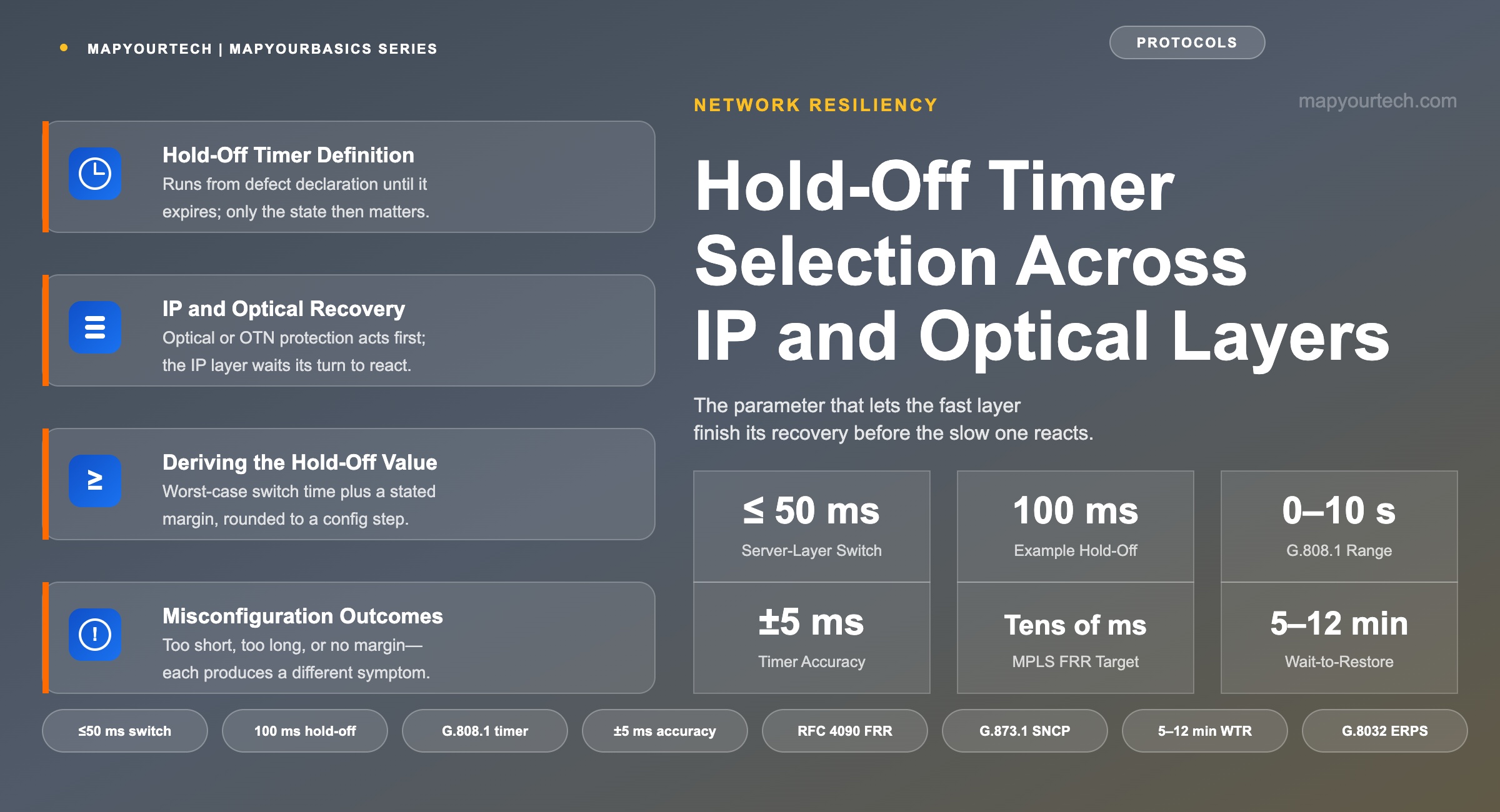
Hold-Off Timer Selection Across IP and Optical Layers
Sizing the timer that lets optical or OTN protection finish its own recovery before the IP layer reacts to a fault it never needed to see.
Detection time is part of the recovery budget and usually the largest part.
1. Introduction
A fibre cut on a path carrying both an IP/MPLS adjacency and its underlying optical circuit can trigger two independent recovery mechanisms at once: the optical or OTN layer's own protection switch, and the IP layer's routing or fast-reroute response to the same lost signal. Both mechanisms are frequently correct in isolation, and the pair can still produce a worse outcome together than either would alone, because the IP layer's reaction lands on a topology the optical layer has already repaired.
The hold-off timer is the parameter that resolves the order between them. It delays a layer's own recovery action long enough for a faster, lower layer to attempt its fix first, and only proceeds if that fix does not arrive in time. ITU-T G.808.1 defines the mechanism generically for nested and cascaded protection domains, and ITU-T G.873.1 extends it explicitly to the boundary between a server layer and a client layer — precisely the IP-over-optical case this article works through.
This article derives the hold-off timer's correct value from the optical or OTN layer's worst-case protection-switching time plus an explicit margin, and works through what happens at three wrong settings: a timer that is too short, one that is too long, and one that carries no margin at all. The scope is the coordination parameter itself, not the protection mechanisms it coordinates; 50 ms protection switching: SDH, OTN, MPLS-TP and IP/MPLS covers those architectures in full and is the companion reference for the timing figures used here.
2. Hold-Off Timer Definition and Recovery Timing Components
A hold-off timer is a configurable interval, provisioned at a protection selector or client-layer interface, that runs from the moment a signal-fail or signal-degrade condition is declared and suppresses any protection-switching action until it expires. Only the defect state present at expiry reaches the switching process; a condition that clears earlier triggers nothing.
Three adjacent quantities get folded into "hold-off" in casual use, and the confusion is worth clearing before going further. Detection time is the interval before a defect is even declared and ends where the hold-off timer begins, so lengthening one does not lengthen the other. The Wait-to-Restore (WTR) timer governs the move back to the working path once a fault clears — provisionable from 5 to 12 minutes with a 5-minute default (standard-specified, ITU-T G.808.1) — the reverse direction of the same coordination problem, not the same timer under a different name. The server layer's own switch-completion time is what the hold-off timer is sized against, not a property of the hold-off timer itself.
The sizing relationship is one line: Thold-off ≥ Tswitch, worst-case + Tmargin, every term in milliseconds. For an IP interface riding an optical path whose linear protection completes within 50 ms (standard-specified, ITU-T G.873.1), a hold-off timer of 100 ms — itself one of the timer's own 100 ms configuration steps — leaves 50 ms of margin, comfortably covering the timer's stated ±5 ms accuracy and ordinary span-to-span variation.
Takeaway: A hold-off timer is sized against the layer it is waiting for, not against its own switching speed. Get the reference layer wrong and the number that comes out is meaningless, however carefully the arithmetic was done.
3. IP and Optical Layer Recovery Mechanisms
An IP/MPLS adjacency riding a DWDM or OTN path sits above at least one, and often two, independent recovery mechanisms it does not control.
At the optical layer, Optical Line Protection (OLP) switches the receiver between a working and a protect fibre. A 1+1 configuration, where both fibres are lit simultaneously and the receiver selects between them, typically switches in under 20–25 ms; a 1:1 configuration, which must bridge the signal onto an idle protect fibre before switching, typically stays under 50 ms (standard-specified, consistent across carrier deployments). One layer up, at the OTN electrical layer, Sub-Network Connection Protection (SNCP) under ITU-T G.873.1 and shared-ring protection under G.873.2 both target the same sub-50 ms completion time, a figure inherited from the original SDH Multiplex Section Protection objective in ITU-T G.841. Network Protection in Optical Network Architecture covers the full set of linear, ring, and mesh mechanisms behind these numbers.
Where no pre-provisioned protect path exists, a GMPLS- or SDN-controlled mesh restoration function computes and signals a new route after the fact. Because that computation happens only once the failure is already known, restoration typically takes hundreds of milliseconds to several seconds — a different mechanism with a different time constant from protection switching, a distinction this site's treatment of resiliency and survivability develops at length.
The IP/MPLS layer carries its own, separate set of mechanisms. RSVP-TE Fast Reroute, specified in IETF RFC 4090, redirects traffic onto a pre-signalled bypass tunnel at the point of local repair and is designed to complete in tens of milliseconds once a failure is detected (standard-specified design goal) — close enough to the optical layer's own speed class that the two mechanisms genuinely compete for the same fault. Plain IGP reconvergence, without Fast Reroute or a loop-free alternate, floods the topology change and then computes a new shortest path; even with aggressive hello and SPF tuning this commonly takes several hundred milliseconds, and an untuned deployment can take a few seconds.
Every one of these mechanisms is triggered by the same observable — loss of the optical or electrical signal — and every one is authorized to act on it independently unless something tells it to wait. An architecture built without that coordination reacts three times to a fault that only happened once, the exact failure mode a coordinated multilayer design exists to prevent.
| Layer / mechanism | Path basis | Typical completion | Evidence class |
|---|---|---|---|
| Optical line protection (OLP), 1+1 | Pre-provisioned, permanently bridged | < 20–25 ms | Standard / vendor-consistent |
| Optical line protection (OLP), 1:1 | Pre-provisioned, switched bridge | < 50 ms | Standard / vendor-consistent |
| OTN SNCP / ODUk linear (G.873.1) | Pre-provisioned, bridge and selector | < 50 ms | Standard-specified |
| OTN shared ring (G.873.2) | Pre-provisioned, shared ring bandwidth | < 50 ms | Standard-specified |
| GMPLS / SDN mesh restoration | Computed after the fault | Hundreds of ms – several s | Typical |
| MPLS Fast Reroute (RFC 4090) | Pre-signalled bypass tunnel | Tens of ms | Standard-specified design goal |
| IGP reconvergence, no FRR | Recomputed after the fault | ~300 ms – a few s | Typical, tuning-dependent |
4. Deriving the Hold-Off Timer Value
The relationship introduced in Section 2 is the whole derivation; what it takes to apply correctly is choosing the right value for each term rather than guessing at the result.
Hold-Off Timer Sizing Relationship
Thold-off ≥ Tswitch, worst-case + Tmargin
Where:
- Thold-off — the configured interval at the client-layer selector or interface, in ms. ITU-T G.808.1 provisions this from 0 to 10 s in 100 ms steps, with a timer accuracy of ±5 ms.
- Tswitch, worst-case — the server layer's own worst-case protection-switching completion time, in ms, taken from its governing standard or from field-measured data for that span and equipment generation — never a best-case or average figure.
- Tmargin — an explicit allowance covering the hold-off timer's own ±5 ms accuracy, the 100 ms step it is configured in, and any span-specific variation not already captured in the worst-case figure.
Consider an IP interface whose underlying path is protected by OTN SNCP with a standard-specified worst-case completion of 50 ms. Setting the hold-off timer to the next available 100 ms step above that worst case leaves 50 ms of margin, comfortably covering the timer's own accuracy and ordinary span-specific variation. If the SNCP switch completes inside its 50 ms budget, the hold-off timer is still running when the signal reappears; the IP interface never registers the outage and never reconverges. If the SNCP switch does not complete — a double fault, a protect path that has itself failed — the hold-off timer expires at 100 ms, the IP layer reads a signal that is still down, and its own recovery proceeds on schedule, 50 ms later than it would have run without coordination and with no second disturbance to show for the wait.
Practical Example — sizing a hold-off timer for a metro DCI ring
A metro DCI ring carries an IP/MPLS adjacency between two routers over an OTN path protected by G.873.2 shared-ring switching, standard-specified at under 50 ms within the recommendation's circumference and node-count bounds. Field measurements on the ring's worst span show the switch completing in 38 ms, comfortably inside that budget. Rounding up to the nearest 100 ms configuration step and adding one further step of margin gives a 200 ms hold-off — generous against the 38 ms measured worst case, but the extra step costs nothing against a 50 ms-class fault and buys tolerance for a slower day the field measurement did not happen to catch.
The hold-off timer and the Wait-to-Restore timer answer different questions and are set independently. Hold-off governs the move onto protection; WTR, typically 5 to 12 minutes by default (standard-specified, ITU-T G.808.1), governs the move back once the fault clears. Undersizing WTR reintroduces the same race in reverse — a premature return to a working path the server layer has only just, and not yet stably, restored. Clock Types and the Telecom Synchronization Hierarchy covers the separate question of timing accuracy across a network, which is where the hold-off timer's own ±5 ms tolerance comes from.
Takeaway: The hold-off timer's correct value is arithmetic, not a round number chosen to feel safe — the server layer's own worst-case switching time plus a stated margin, rounded up to an available configuration step. No other basis for the number holds up once a double disturbance gets traced back to it.
5. Hold-Off Timer Misconfiguration Outcomes
A hold-off timer that is not sized against the server layer's worst-case switching time fails in one of three distinct ways, and each produces a different, diagnosable symptom.
Shorter than the server layer's worst-case switch time. If the hold-off interval expires before the optical or OTN layer has finished its own switch, the IP layer starts reconverging around a fault the lower layer was already correcting. The router's reroute typically completes first, because IP-layer mechanisms operate on their own pre-signalled paths, and when the optical switch finishes a few milliseconds later, the newly stable underlying path pulls the IP layer through a second change to revert. One fault produces two routing events instead of one, and the second event is entirely avoidable.
Longer than necessary, with no server-layer recovery available. An oversized hold-off costs nothing when the server layer succeeds, because the client layer never has to act. It costs the full unused interval when the server layer does not succeed: a double fibre cut, a protect path that has itself failed, a mesh restoration function that cannot find a route. A hold-off set to several seconds "to be safe" turns what should be a sub-second IP-layer recovery into a multi-second outage precisely when the fast layer's own fix is unavailable — the exact scenario the IP layer's recovery mechanism exists to catch.
Equal to the server layer's typical switch time, with no margin. A hold-off timer set exactly to the server layer's typical, rather than worst-case, switching time behaves correctly on an ordinary day and fails on the day that matters. Optical-layer switch times vary with span length, the number of channels caught in a shared alarm, and the specific equipment generation on that segment; a 50 ms typical figure with no margin added will occasionally meet a 58 ms actual switch, and the result is the same double disturbance as the too-short case above — intermittent, and difficult to reproduce against a fault injection cleaner than the field ever is.
| Setting | Behaviour | Consequence |
|---|---|---|
| Shorter than the server layer's worst-case switch time | Client-layer recovery starts before the server-layer switch completes | Two disturbances from one fault; the client-layer action often reverts once the server layer stabilises |
| Longer than necessary, no server-layer recovery available | Client layer waits out the full interval though nothing is repairing the fault | Outage extends by the unused remainder of the hold-off interval |
| Equal to typical switch time, no margin added | Correct on a typical fault, incorrect whenever the actual switch time exceeds typical | Intermittent double disturbances tied to the worst-performing instances of the fault |
6. Applications and Deployment Scenarios
Coordination matters most where both layers are fast enough to compete for the same fault, and least where one of them is clearly and permanently slower.
Data centre interconnect. Coherent pluggables — 400ZR and its successors — increasingly sit directly in routers and switches, collapsing the optical and IP layers onto the same faceplate. The OIF's 800ZR implementation agreement specifies a consequent-action hold-off inside the pluggable itself: a user-configurable interval (standard-specified, OIF-800ZR-01.0) that delays inserting a local-fault or squelch signal toward the host after a media-side defect, so a transient impairment that clears in time never reaches the router's own fault-handling logic at all. A value of zero — no hold-off — is the specification's required default, so a deployment has to opt in deliberately to gain the benefit. It is the same mechanism this article describes, applied one layer down, inside the optic rather than between two separate network elements; Turn-Up, Retune, and Reacquisition Timing in Coherent Interfaces works through the related case where hold-off is deliberately left at zero because no lower layer exists to wait for.
Metro rings. An OTN or Ethernet ring running G.873.2 or G.8032 protection completes its switch, within the recommendation's own circumference and node-count bounds, in under 50 ms. An IP/MPLS layer riding a simplified open line system or a traditional ring should hold off by a value derived exactly as in Section 4 — the ring's own worst-case switch time plus margin, not a default carried over unchanged from a different topology.
Long-haul and submarine. Where the underlying path relies on GMPLS-computed mesh restoration rather than pre-provisioned protection, the server layer's own recovery routinely takes seconds rather than tens of milliseconds, and on a submarine segment a wet-plant fault is not physically repaired for weeks regardless of how the electrical layers are tuned. The hold-off calculation still applies, but the number it produces is large enough that the IP layer's own recovery, not the transport layer's, becomes the primary defence; the timer's role shifts from suppressing an unnecessary reroute to bounding how long the network waits before accepting that one is required.
Practical Example — a hyperscaler DCI backbone
A hyperscaler backbone carries 400ZR-class pluggables directly in the routers over a simplified open line system, with router-layer ECMP as the only IP-layer recovery and optical restoration, rather than dedicated protection, underneath it. Because the optical layer here is restoration-based rather than protection-based, its recovery time runs to hundreds of milliseconds or more — closer to the IP layer's own reconvergence time than to the 50 ms class of a protected path. The hold-off calculation still holds, but the margin has to absorb a much wider spread of possible optical-layer outcomes, and the trade-off becomes explicit: accept a longer hold-off and let the IP layer wait, or accept that ECMP will sometimes react before optical restoration finishes.
7. Standards and Vendor Support
The hold-off timer is not a proprietary feature; it is part of the base protection-switching model every relevant standard shares. ITU-T G.808.1 defines it generically for nested and cascaded linear and ring protection; ITU-T G.873.1 and G.873.2 apply it explicitly at the OTN server-to-client boundary; ITU-T G.8032 carries the same parameter into Ethernet ring protection; and the OIF's 800ZR implementation agreement applies the identical principle inside a pluggable coherent optic. IETF RFC 4090 does not define a hold-off timer of its own — Fast Reroute is itself the fast, competing mechanism a hold-off timer would otherwise be protecting a slower layer against, which is exactly why FRR and optical-layer protection need explicit coordination whenever both sit on the same path.
Router and optical-transport vendors expose the parameter under different names but the same behaviour: a configurable delay between defect declaration and protection-switching action, on both router interfaces and optical line systems, from vendors including Cisco, Juniper, Nokia, Ciena, Infinera, and Ribbon Communications. Coordination is increasingly handled above the individual network element as well; Ribbon's Muse multilayer automation platform, for one, is positioned to orchestrate recovery across the optical and packet domains from a single control point, following the same escalation logic derived by hand in Section 4: let the fastest applicable layer act first, and hold off everything above it until that attempt has had its chance.
8. Automated Multilayer Recovery Coordination
Manual hold-off configuration assumes the network's layering is static and its worst-case switch times are known in advance. Neither assumption holds as networks disaggregate: an open line system from one vendor, a coherent pluggable from another, and a router control plane from a third can each change independently, and a hold-off value calculated for one hardware generation does not automatically carry over to the next.
Streaming telemetry and SDN-based multilayer management close part of this gap by making the server layer's actual, rather than assumed, switching performance directly observable to the layer above it. Where a controller has visibility into both the optical and IP domains, the hold-off decision can move from a static, pre-configured timer toward a value informed by that specific path's own recent switching history, still governed by the same worst-case-plus-margin arithmetic but with the worst case measured rather than looked up in a table. That shift does not remove the need to understand the underlying timing budget; it changes who, or what, is doing the arithmetic.
Takeaway: Automating the hold-off decision changes how the worst-case switching time is obtained. It does not change the relationship between that number and the timer built on top of it.
9. Conclusion
Layer coordination is a provisioning decision rather than a property either layer holds on its own. An optical line system that switches in 50 ms and a router that reroutes in tens of milliseconds are each behaving correctly; the second disturbance comes from the two acting on one fault without an agreed order between them, and the hold-off timer is where that order is written down.
The value follows from the server layer's worst-case switching time plus a stated margin, and the derivation is short enough to redo whenever the path changes:
- Identify which recovery mechanism actually protects that specific path — pre-provisioned protection or after-the-fact restoration. The two differ by an order of magnitude in completion time.
- Take the worst-case switching time from the governing recommendation, or from field measurement on the worst span, never a typical or average figure.
- Add a margin covering the timer's own accuracy, its configuration step size, and span-to-span variation.
- Round up to the next available configuration step and provision that value.
- Record the server-layer figure the value was derived from, so a later reviewer can check the arithmetic instead of guessing at the intent.
- Re-derive whenever the underlying path, protection scheme, or equipment generation changes — a value calculated for one hardware generation does not carry forward automatically.
Takeaway: A hold-off timer with no recorded derivation is indistinguishable from a guess, and behaves like one on the day the server layer takes longer than usual to switch.
10. References
- ITU-T G.808.1 — Generic Protection Switching: Linear Trail and Subnetwork Protection, ITU-T Study Group 15.
- ITU-T G.873.1 — Optical Transport Network: Linear Protection, ITU-T Study Group 15.
- ITU-T G.8032 — Ethernet Ring Protection Switching, ITU-T Study Group 15.
- IETF RFC 4090 — Fast Reroute Extensions to RSVP-TE for LSP Tunnels, Internet Engineering Task Force.
Related Articles on MapYourTech