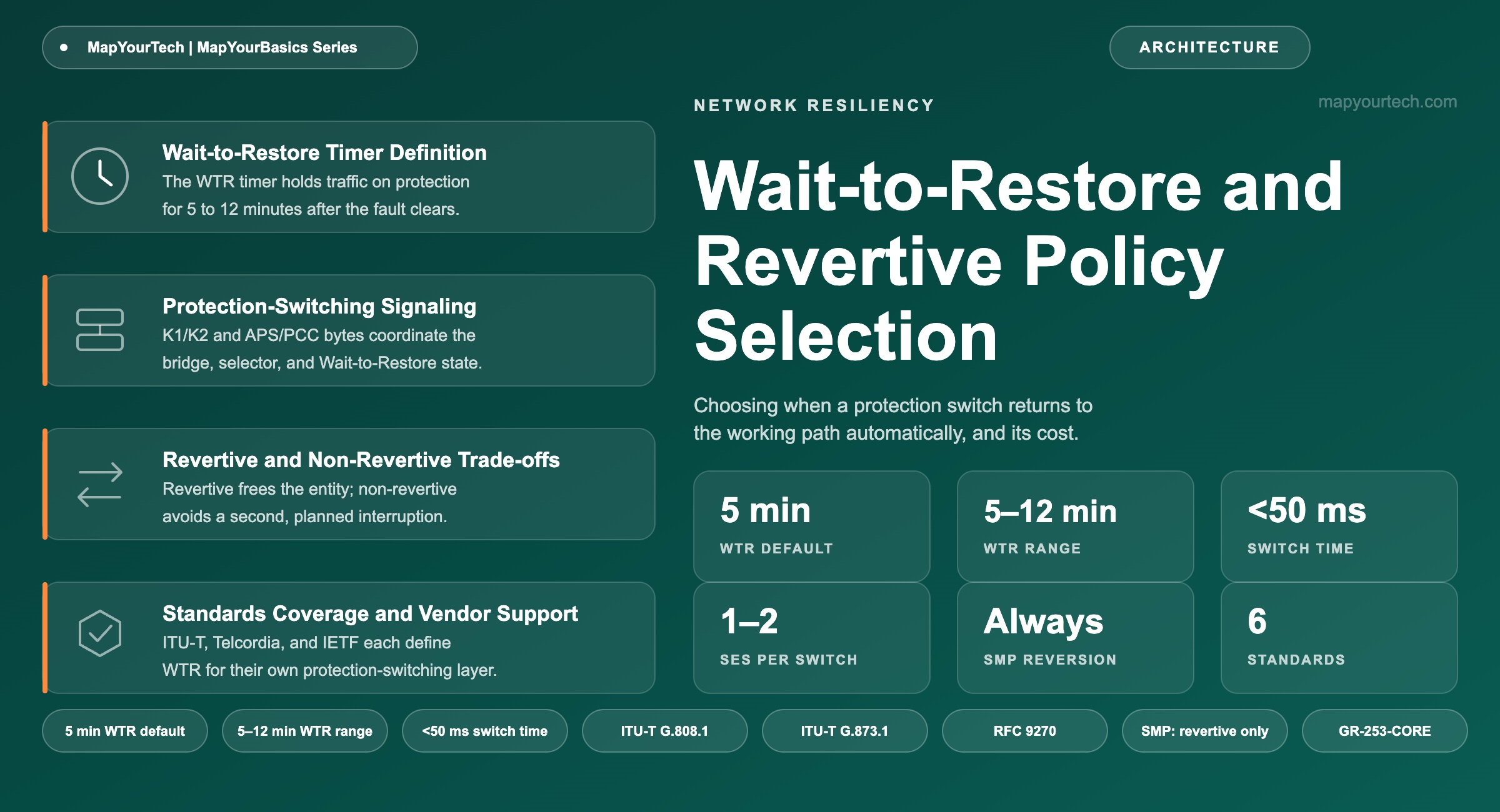
Wait-to-Restore and Revertive Policy Selection
Choosing when a protection switch should return to the working path automatically, and what it costs when it does not.
Protection is provisioned in advance; restoration is computed after the failure.
1. Introduction
A protection switch that returns traffic to the working path is not free. The revert is a second break in service, executed by the same selector hardware that moved traffic away from the fault in the first place, and it registers in the path's performance record as one or two severely errored seconds (standard-specified, ITU-T G.808.1). A wait-to-restore (WTR) timer exists to make that second break happen at most once per repair, not once per flicker of an intermittent fault.
Every automatic protection switching (APS) architecture in current use — SONET and SDH linear and ring protection, Optical Transport Network (OTN) Sub-Network Connection Protection (SNCP), Ethernet linear and ring protection, and the shared mesh protection used in Generalized Multi-Protocol Label Switching (GMPLS)-controlled optical networks — makes the same two decisions for every protected path: whether to return traffic to the working entity automatically once it recovers (revertive operation), and, if so, how long to wait before doing it. Some architectures leave both open to policy; others decide the first question for the operator by design. This article works through what the WTR timer actually delays, why revertive and non-revertive operation trade a second interruption against a standing cost in latency and capacity, and why that trade comes out differently depending on whether the protection entity in question belongs to one working path or to several.
2. Wait-to-Restore Timer Definition
The wait-to-restore (WTR) timer is the interval a protection-switching system holds traffic on the protection path after the working path's fault-clear condition is confirmed, expressed in minutes and counted from the moment that condition first becomes continuously true. WTR applies only under revertive operation; a non-revertive path carries no WTR value because it never switches back automatically. The fault-clear condition itself is the sustained absence of a Signal Fail (SF) or Signal Degrade (SD) indication — the same two defect types that triggered the original switch to protection.
The same sequence plays out below as a walkthrough. The single-fault case runs the timer once to zero; the flapping-fault case shows the timer restarting when a second defect arrives inside the window — the behavior the timer exists to produce.
Interactive Walkthrough — Fault, Wait, and Revert
Single fault: one clean recovery — the fault clears once and stays clear, so the timer runs to zero and traffic reverts.
Reduced-motion is on, so the sequence advances in steps without continuous movement.
WTR is easy to conflate with two other intervals in the same event, and the three serve different purposes. A hold-off timer sits at the opposite end of the sequence: it delays declaring a fault to the protection-switching function long enough for a faster, lower layer to react first, so a client-layer or optical-layer protection scheme gets the first attempt before a slower one escalates. Switch completion time is the duration of the interruption itself — under 50 milliseconds for SONET, SDH, OTN, and Ethernet linear and ring schemes aligned to ITU-T G.808.1 — and it applies equally to the switch away from the fault and the later switch back; WTR contributes no interruption on its own, only the timing of when the next one happens. Revertive operation, in turn, is the policy choice itself, a yes-or-no setting; WTR is the numeric parameter that only has meaning once that setting is yes.
- T(revert) — wall-clock time the revert switch executes
- T(clear) — wall-clock time the fault-clear condition first becomes continuously true
- WTR — wait-to-restore interval, in minutes (5–12 min, default 5 min; standard-specified, ITU-T G.8031, G.873.1)
ITU-T G.783 permits configuring WTR down to 0 minutes for an immediate revert. At that setting, an intermittent fault reverts and switches again on every cycle — the exact behavior WTR exists to prevent. Most deployments leave WTR at or near the 5-minute default rather than minimizing it.
Takeaway: WTR delays only the return trip. It does not change how fast the network reacts to the original fault, and outside revertive operation the parameter carries no meaning at all.
3. Protection-Switching Architecture and the WTR State
A protection group consists of a working entity, a protection entity, a bridge at the transmit end, and a selector at the receive end, coordinated over a signaling channel carried on the protection entity itself — the K1 and K2 overhead bytes in SONET and SDH, or the 4-byte Automatic Protection Switching / Protection Communications Channel (APS/PCC) field in OTN, which is similar in structure to the SONET and SDH K bytes (ITU-T G.873.1). The channel carries a small set of request codes — Signal Fail (SF), Signal Degrade (SD), Manual Switch, Forced Switch, Wait-to-Restore, Exercise, and No Request — and, in OTN's APS/PCC field, an explicit bit marking the group as revertive or non-revertive.
When the working entity clears an SF or SD condition, the tail-end node does not resume normal traffic immediately. It enters a local wait-to-restore state, signals that state to the head-end over the same channel, and starts the WTR timer. The state is given the highest priority of any non-fault request, so a second SF or SD anywhere in the group pre-empts it and restarts the timer from the point of the new defect. When the timer expires with no intervening request, the state changes to No Request and the selector reconnects to the working entity — the revert switch.
Non-revertive operation removes the WTR step from that sequence without changing anything before it. In place of the wait-to-restore request, the tail-end asserts Do Not Revert (DNR), a low-priority request that keeps the selector pointed at the protection entity indefinitely. Fault detection and the first switch behave identically either way; only the return trip is skipped, and it stays skipped until an operator issues a manual command.
3.1 Shared Protection Entities and the Revert Requirement
The consequence of skipping the return trip depends on what else depends on that specific protection entity. In 1:N linear protection, n working entities share a single protection entity over the same signaling channel, and the entity carries low-priority extra traffic whenever no working entity is using it. A working entity that stays on the shared entity after its fault clears keeps that extra traffic pre-empted and leaves every other working entity in the group without a protection entity until it is released — a second, independent fault elsewhere in the group has nowhere to switch to. Shared mesh protection at the Optical Data Unit (ODU) layer (ITU-T G.808.3 and G.873.3) generalizes the same arrangement across a pre-computed, pre-configured pool of backup entities serving many working paths at once, and the IETF's GMPLS signaling extensions for the mechanism state the consequence directly: shared mesh protection is always revertive (RFC 9270).
A dedicated 1+1 pair carries no such consequence. The protection entity is permanently bridged to one working entity and reserved for it alone, so parking traffic there after a repair costs that one connection its second interruption and nothing more. ITU-T G.873.1 notes this directly: 1+1 protection is commonly provisioned non-revertive for exactly this reason, since the dedicated arrangement avoids the second switch with no consequence for any other path.
4. Revertive and Non-Revertive Trade-offs
Revertive operation guarantees a second interruption on every fault that clears — the same sub-50-millisecond switch and the same one or two severely errored seconds as the original fault, timed by the WTR window instead of by the defect. The risk WTR is built to absorb is a flapping link: without the timer, a fault that clears and reappears within seconds would trigger a switch on every cycle. With it, any SF or SD inside the WTR window restarts the timer instead of letting a partial recovery revert, so an intermittent fault produces one extended stay on protection rather than a string of short ones.
Non-revertive operation removes that second interruption entirely, and ITU-T G.873.1 names this as its main advantage for dedicated protection. What it costs depends on what the protection path actually is. Working and protection paths are rarely engineered to the same length: the working path is usually the direct, shortest route, and the protection path the diverse, physically separated one that route-diversity and Shared Risk Link Group (SRLG) rules require. A connection left on protection non-revertively carries that path's longer propagation delay for as long as it stays there, not just for the duration of the original fault — an open-ended latency cost rather than a one-time one, and the reason financial-trading and other latency-committed links tend to pair non-revertive tolerance with the shortest achievable diverse pair, or avoid non-revertive operation entirely. Where the protection entity carries preemptible extra traffic, as 1:1 and 1:N architectures typically allow, staying on protection also keeps that extra traffic preempted, turning a technical parking decision into a standing capacity cost.
The two costs are not symmetric across architectures. A dedicated 1+1 pair pays only the latency cost, and only for the one connection sitting on protection non-revertively, because the capacity cost does not arise when nothing else needs that entity. A shared 1:N group or an ODU shared-mesh-protection pool pays both: the parked connection carries its longer path indefinitely, and the group loses its spare capacity for every other member until someone reverts it — which is why standard practice treats revertive operation as close to mandatory once protection capacity is shared rather than dedicated.
| Attribute | Revertive | Non-Revertive |
|---|---|---|
| Standard default (ITU-T G.8031, G.8032, G.873.1) | Yes | Requires explicit Do Not Revert configuration |
| Interruptions per fault-and-repair cycle | Two — switch away, then switch back | One — switch away only |
| Typical use | 1:N and shared mesh protection; most long-haul and metro deployments | Dedicated 1+1 pairs carrying no shared or extra traffic |
| Effect on a shared protection pool | Frees the entity for the next fault once WTR expires | Entity stays occupied; other members of the group are unprotected |
| Effect on path latency once repaired | None — traffic returns to the shorter, engineered path | Standing cost if the protection path differs in length or route |
| Manual step needed to restore the working path | None | Yes — an operator-issued command |
5. Deployment Patterns by Protection Architecture
Long-haul and submarine systems on route-diverse working and protection pairs default to revertive operation for the same reason most shared architectures do: the working path is the engineered, typically shorter route, and returning to it both restores the path's designed latency and frees the diverse route for its next assignment. A single span failure on a route with a multi-hour or multi-day mean time to repair for the fiber itself still completes its protection switch in under 50 milliseconds; what WTR governs is only the handful of minutes after the physical repair, not the outage in between.
Financial-trading and other latency-committed point-to-point links carry the sharpest version of the latency cost described above. Operators serving this traffic class typically engineer the working and protection paths to the smallest achievable length difference and still default to revertive operation, because even a closely matched pair rarely reaches zero difference, and a standing cost measured in fractions of a millisecond has a priced effect on that traffic.
Dedicated 1+1 fiber-pair and Y-cable transponder protection on a ROADM degree are the cases where non-revertive operation is a genuine, standards-endorsed choice rather than a compromise. Because the protection entity is permanently bridged to one working entity and carries no extra traffic, parking a repaired connection there costs that connection its own latency difference and nothing else — an operator can defer the manual revert to a scheduled maintenance window instead of accepting an automatic switch at an arbitrary moment.
1:N linear protection and ODU shared mesh protection sit at the other end of the same spectrum. Because the protection entity or pool is shared, non-revertive operation is rarely offered as a supported configuration in the first place; shared mesh protection is standardized as always revertive for exactly this reason. Metro Ethernet rings under G.8032 fall in between: revertive operation is the near-universal default, but an operator troubleshooting a known intermittent link sometimes sets a ring non-revertive deliberately, for the duration of the investigation, specifically to stop the ring from reverting into a link that is expected to fail again — then reverts it manually once the link is actually repaired.
Practical Example — reverting a 1:N linear protection group after a fiber repair
Three 100 Gb/s OTU4 (Optical Transport Unit level 4) working entities share one protection entity in a 1:N group. A fiber cut takes Working 2 down; the group's APS protocol bridges it onto the shared protection entity within the standard's sub-50-millisecond window, and the protection entity's extra-traffic channel — until then carrying a lower-priority best-effort service — is pre-empted for the duration. Field crews restore the fiber some hours later. The moment Working 2's Signal Fail condition clears continuously, the tail-end node enters its local WTR state and starts a 5-minute timer, the standard default. No further SF or SD is declared in that window, so at the 5-minute mark the selector reconnects to Working 2, the protection entity returns to No Request, and the extra-traffic channel becomes available again — for Working 1 or Working 3's next fault, or for the best-effort traffic it was carrying before. Had the group been configured non-revertive, Working 2 would have stayed on the shared entity indefinitely, and a fault on Working 1 in the interim would have had no protection entity to switch to at all.
Multi-layer deployments add a further wrinkle: a hold-off timer at a higher layer — client-layer protection, or an IP/MPLS Fast Reroute policy riding above an optical or OTN path — delays that layer's own switch long enough for the faster optical or OTN protection to attempt recovery first. WTR operates independently of that hold-off; it governs only the return trip of the layer it belongs to, so a multi-layer design typically carries a distinct, correctly ordered WTR value at each layer rather than one shared setting. OTN Sub-Network Connection Protection adds a further, independent choice layered on top of revertive policy: which of the three ITU-T G.873.1 monitoring modes — inherent (SNC/I), non-intrusive (SNC/N), or sub-layer (SNC/S) — detects the fault that starts the sequence. The monitoring mode changes how and where a defect is declared; it does not change how WTR behaves once a defect clears. The same layering shows up in 5G transport, where an xHaul path riding OTN inherits the same revertive default and the same 5-minute WTR window as any other ODUk connection on the network.
Takeaway: whether non-revertive operation is available at all is usually decided by the protection architecture, not by preference — dedicated pairs allow it, shared pools generally do not.
6. Standards Coverage and Vendor Support
Wait-to-restore behavior traces to one architectural definition and several layer-specific implementations of it. ITU-T G.808.1 defines the generic vocabulary — revertive and non-revertive operation types, the WTR mechanism, and its recommended interval — and each layer standard applies the same mechanism to its own overhead channel: ITU-T G.873.1 for OTN linear and subnetwork connection protection, ITU-T G.8031/Y.1342 for Ethernet linear protection, and ITU-T G.8032/Y.1344 for Ethernet ring protection switching (ERPS). Telcordia GR-253-CORE carries the equivalent requirement for SONET, and ITU-T G.783 for SDH, with a switch-completion budget of 60 milliseconds split roughly 10 milliseconds for fault detection and 50 milliseconds for the switch itself — the figure the industry shorthands as "50 ms." Every one of these sets WTR as an operator-configurable value across a 5-to-12-minute window with 5 minutes as the default (standard-specified), a figure that has held across every layer standard built on the original SDH multiplex-section-protection specification.
Shared mesh protection is the one architecture in this group that removes the choice rather than setting a default. ITU-T G.808.3 and G.873.3 define the mechanism, and the IETF's GMPLS signaling extensions for it state plainly that the scheme is always revertive (RFC 9270), because a pre-reserved backup entity has to be released back to the shared pool for the mechanism to keep working across multiple, independent failures.
| Standard | Scope | WTR Range | WTR Default | Switch Time |
|---|---|---|---|---|
| ITU-T G.808.1 | Generic protection switching architecture | 5–12 min | 5 min | <50 ms |
| ITU-T G.873.1 | OTN linear / subnetwork connection protection | 5–12 min | 5 min | <50 ms |
| ITU-T G.8031/Y.1342 | Ethernet linear protection switching | 5–12 min | 5 min | <50 ms |
| ITU-T G.8032/Y.1344 | Ethernet ring protection switching (ERPS) | typically 5–12 min | 5 min | <50 ms per link |
| Telcordia GR-253-CORE / ITU-T G.783 | SONET / SDH automatic protection switching | 5–12 min | 5 min | <60 ms |
| ITU-T G.808.3 / G.873.3 | ODU shared mesh protection | n/a — always revertive | n/a | 50 ms – sub-second |
Configurable WTR and Do Not Revert support ships as a standard function of automatic protection switching on current optical-transport and OTN switching platforms, not as an optional add-on — vendors including Ciena, Nokia, Cisco (including its Acacia coherent-optics business), Infinera, and Ribbon each implement ITU-T G.808.1-aligned protection switching across their line systems and OTN cross-connects, with WTR exposed as a per-protection-group configuration parameter. Interoperability at the signaling level matters most at OTN and Ethernet administrative-domain boundaries, where the APS/PCC or Ring-APS messages from one vendor's equipment have to be read correctly by another's; the request-code set defined in G.873.1 and G.8031/G.8032 is what makes that interoperability possible rather than any single vendor's implementation.
The service-facing side of a revert switch is worth tracking separately from the protection-layer mechanics above it — a service assurance model that maps a sold circuit to its current resources needs to record the revert as a resource change, not only as a performance event, since the circuit's active path changes at that instant even though its endpoints do not.
7. Emerging Directions in Protection and Restoration Policy
Routed Optical Networking moves protection intelligence for some services onto the IP layer itself, using Segment Routing with Topology-Independent Loop-Free Alternate (TI-LFA) to provide sub-50-millisecond rerouting without a stateful APS-style protocol underneath it. Where that layer carries the protection decision, reversion becomes an Interior Gateway Protocol (IGP) convergence outcome rather than a WTR-timed one: the network reconverges onto its lowest-cost path once the failed link's cost is restored, on a timescale the operator tunes through the IGP rather than through a dedicated timer.
Software-Defined Networking (SDN)-orchestrated shared mesh restoration extends the same pre-provisioned-pool logic that ITU-T G.808.3 and RFC 9270 define for shared mesh protection into networks where a centralized controller, rather than distributed GMPLS signaling, computes and activates the shared backup paths. The reversion requirement does not relax in that shift — a controller-managed pool still needs every member revertive to stay usable for the next independent fault — but the mechanism that enforces it moves from an in-band protocol bit to a controller policy.
Predictive fault detection, which flags degrading optical performance parameters before a hard failure occurs, changes when a protection switch starts but not what WTR does once one completes. A prediction can bring the initial switch forward; it has no defined role in the return trip, since WTR's premise — hold the position until the fault-clear condition has stayed true for a fixed interval — does not depend on how the original fault was detected.
Takeaway: the reversion decision is rarely free-standing. It follows from whether the protection entity belongs to one connection or to a pool, and the standards that define shared protection remove the choice for exactly that reason.
References
- ITU-T G.808.1 — Generic protection switching – Linear trail and subnetwork protection, ITU-T Study Group 15.
- ITU-T G.873.1 — Optical Transport Network (OTN): Linear protection, ITU-T Study Group 15.
- ITU-T G.8031/Y.1342 — Ethernet linear protection switching, ITU-T Study Group 15.
- ITU-T G.8032/Y.1344 — Ethernet ring protection switching, ITU-T Study Group 15.
- Telcordia GR-253-CORE — Synchronous Optical Network (SONET) Transport Systems: Common Generic Criteria, Telcordia Technologies.
- IETF RFC 9270 — GMPLS Signaling Extensions for Shared Mesh Protection, Internet Engineering Task Force.
Related Articles on MapYourTech