
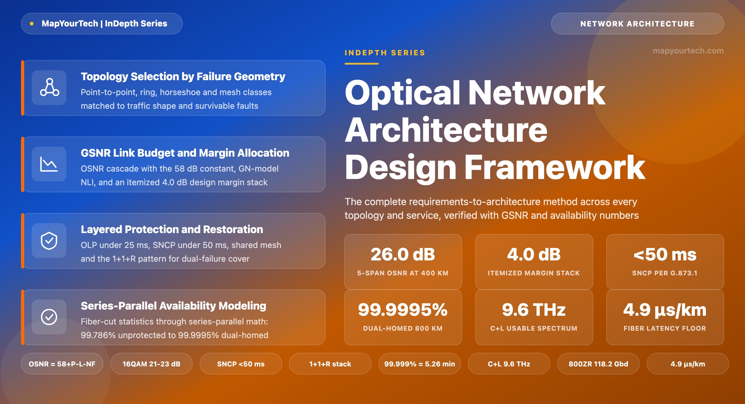
Designing Optical Network Architectures Across Topologies and Services
A requirements-to-architecture framework for optical transport: topology selection, CDC-F ROADM node design, GSNR link budgets, layered protection, and the availability mathematics that verify five-nines targets before any equipment is ordered.
1. Introduction
An optical network architecture is a set of coupled decisions: the shape of the fiber graph, the switching capability placed at each node, the amplification and band plan on each span, the protection and restoration machinery layered over the paths, and the control software that binds them into an operable system. No single choice in that list is "best" in isolation. A colorless, directionless, contentionless, flex-grid (CDC-F) reconfigurable optical add/drop multiplexer (ROADM) mesh is the strongest general-purpose pattern for a national core, yet it is the wrong answer for a 100 km data center interconnect (DCI) where a pair of amplified point-to-point spans carrying pluggable coherent optics delivers the same bits at a fraction of the cost and power. The discipline that separates a working design from a best-in-class one is the mapping from stated requirements to that stack of choices, verified with numbers before hardware is ordered.
Three budgets govern every optical design, and each one is arithmetic rather than opinion. The signal-quality budget resolves to a generalized signal-to-noise ratio (GSNR) figure per candidate path, combining amplifier noise and fiber nonlinearity against the receiver's requirement for the chosen modulation format. The power budget resolves each span and node loss against amplifier gain ranges and launch-power limits. The availability budget resolves component failure rates, fiber cut statistics and repair times through series-parallel probability into an expected annual downtime, which either meets the service-level agreement (SLA) or does not. A proposal that cannot show all three calculations is a sketch, not an architecture.
This article works through the full decision stack for every major topology class and service family. Sections 2 and 3 establish the layered reference model and the availability vocabulary. Sections 4 and 5 cover topology selection and the photonic building blocks: ROADM tiers, coherent transponder generations, amplifier options and fiber types. Sections 6 through 8 are the quantitative core: the optical signal-to-noise ratio (OSNR) and GSNR budget with worked numbers, the protection and restoration toolbox with switching-time classes, and the availability mathematics carried through a complete 800 km example from unprotected three-nines to dual-homed five-nines. Sections 9 through 12 cover spectrum scaling, control-plane architecture, the service-to-architecture matrix and reference combinations per network segment. Sections 13 and 14 close with the failure modes of the design process itself and the technologies now moving from trial to deployment. The working year throughout is 2026, and every figure carries its evidence class: a standard clause, a measured or field-statistic value, a vendor claim, or a theoretical limit.
2. Layered Reference Architecture of Optical Transport
ITU-T G.872 defines the architecture of the optical transport network as a set of layered networks: the optical channel carrying a client payload, the optical multiplex section (OMS) carrying the aggregate wavelength-division multiplexed (WDM) signal between access points, and the optical transmission section covering each amplified span. In deployed practice this standard-specified layering maps onto three equipment layers plus a control plane, and keeping their responsibilities separate is the first architectural decision because each layer recovers from failures at a different speed and cost.
The photonic layer owns capacity and route diversity. It consists of the fiber plant, the amplified spans, and the ROADM nodes that switch whole wavelengths without electrical conversion. Its economics are the best in the stack — a transit wavelength crossing a ROADM consumes no transponder — but its failure domain is the largest: one fiber cut removes every channel on the cable, which is why route diversity is a photonic-layer property that no higher layer can substitute.
The Optical Transport Network (OTN) layer per ITU-T G.709 adds electrical grooming and isolation. Optical Data Unit (ODUk and ODUflex) switching fills wavelengths efficiently from sub-rate clients, gives each client a monitored, isolated container, and supports subnetwork connection protection (SNCP) with standard-specified switching completion inside 50 ms. Beyond 100 Gb/s the line side uses OTUCn framing with FlexO interfaces per the ITU-T G.709.1/.3 series, which is what lets a 400GE client ride a single 400G wavelength or an 800G wavelength carry two of them.
The service layer — IP/MPLS, Segment Routing, Ethernet services per the MEF model — adds per-flow policy, statistical multiplexing and its own fast reroute. The architectural point is coordination: when a fiber is cut, the photonic layer can restore, the OTN layer can switch, and the IP layer can reroute, and an uncoordinated design has all three react at once, producing routing churn on top of an already-recovered transport path. Well-run multi-layer designs assign each failure class a primary recovery layer and hold the others back with timers.
The control plane column in Figure 1 is drawn beside the layers rather than above them because in 2026 it is genuinely shared. A software-defined networking (SDN) controller speaking T-API, OpenConfig or OpenROADM models handles path computation and service provisioning across layers; a distributed GMPLS/WSON control plane, where deployed, executes fast mesh restoration close to the hardware; the network management system (NMS) and streaming telemetry carry the measured state — per-channel power, pre-forward-error-correction (pre-FEC) bit error ratio, OSNR — that every recovery and planning decision consumes. Section 10 returns to this split in detail.
Takeaway: Assign every function to the cheapest layer that can perform it: capacity and route diversity to photonics, grooming and deterministic sub-50 ms protection to OTN, per-flow policy to packet. Then assign each failure class one primary recovery layer, because three layers reacting to one cut is an outage multiplier, not a safety net.
3. Service Requirements and Availability Classes
Architecture starts with requirements capture, and the requirement that shapes an optical design more than any other is the availability target, because it decides how much of the network must be built twice. Availability is expressed in "nines": the fraction of a year a service is expected to be up. The arithmetic is fixed — a year contains 525,600 minutes, so unavailability of 10−5 (five-nines, 99.999%) permits 5.26 minutes of downtime per year, while three-nines permits 8.76 hours. These are standard definitions, and Figure 2 with Table 1 shows how steep the ladder is: each added nine divides the allowance by ten, and each division is purchased with diversity rather than with better single components.
Read the Full Analysis with Premium
The remaining 88% of this article — the design numbers, trade-offs and field guidance — is part of MapYourTech Premium, along with the full premium library, courses and professional tools.
You May Also Like
-
Free
-
August 27, 2026
-
Free
-
August 27, 2026