NeoClouds: An Introduction for Optical Engineers Skip to main content MapYourTech | MapYourBasics Series NeoClouds: An Introduction for Optical Engineers...
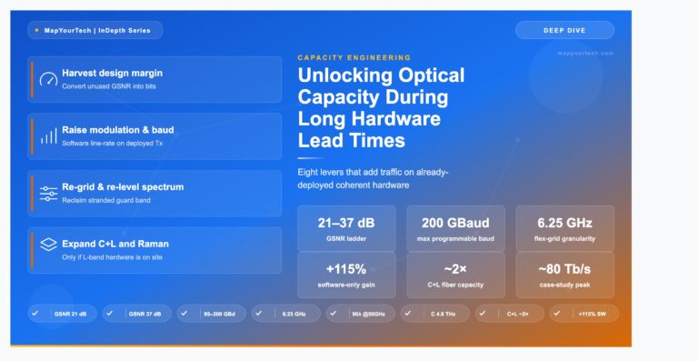
Unlocking Optical Capacity During Long Hardware Lead Times Skip to main content MAPYOURTECH | CAPACITY ENGINEERING Unlocking Optical Capacity During...
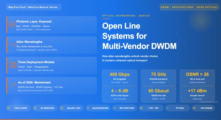
Open Line Systems: Multi-Vendor Coherent Wavelengths Skip to main content MapYourTech · MapYourBasics Series Open Line Systems: Multi-Vendor Coherent Wavelengths...
Get new articles, courses & exclusive offers first
Follow MapYourTech on LinkedIn for exclusive updates — new technical articles, course launches, member discounts, tool releases, and industry insights straight to your feed.