
Optical Amplifiers (OAs) are key parts of today’s communication world. They help send data under the sea, land and even in space .In fact it is used in all electronic and telecommunications industry which has allowed human being develop and use gadgets and machines in daily routine.Due to OAs only; we are able to transmit data over a distance of few 100s too 1000s of kilometers.
Classification of OA Devices
Optical Amplifiers, integral in managing signal strength in fiber optics, are categorized based on their technology and application. These categories, as defined in ITU-T G.661, include Power Amplifiers (PAs), Pre-amplifiers, Line Amplifiers, OA Transmitter Subsystems (OATs), OA Receiver Subsystems (OARs), and Distributed Amplifiers.
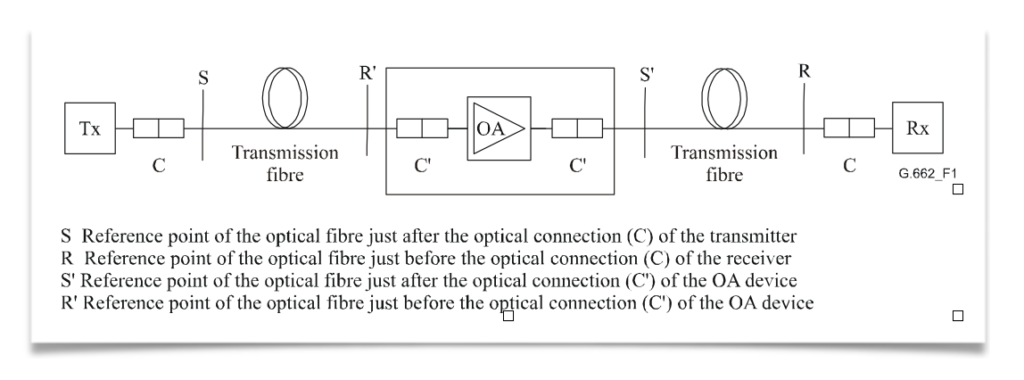
Scheme of insertion of an OA device
- Power Amplifiers (PAs): Positioned after the optical transmitter, PAs boost the signal power level. They are known for their high saturation power, making them ideal for strengthening outgoing signals.
- Pre-amplifiers: These are used before an optical receiver to enhance its sensitivity. Characterized by very low noise, they are crucial in improving signal reception.
- Line Amplifiers: Placed between passive fiber sections, Line Amplifiers are low noise OAs that extend the distance covered before signal regeneration is needed. They are particularly useful in point-multipoint connections in optical access networks.
- OA Transmitter Subsystems (OATs): An OAT integrates a power amplifier with an optical transmitter, resulting in a higher power transmitter.
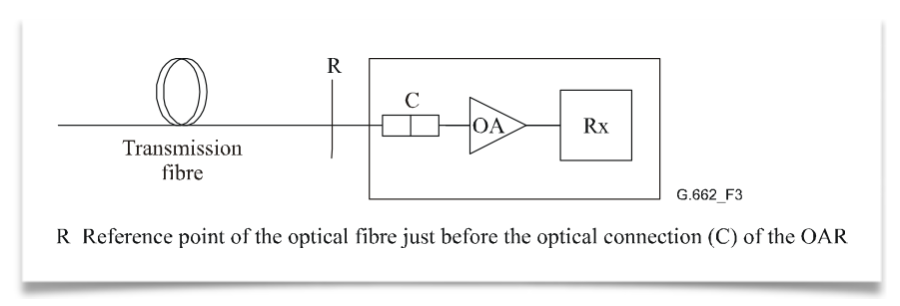
- OA Receiver Subsystems (OARs): In OARs, a pre-amplifier is combined with an optical receiver, enhancing the receiver’s sensitivity.
- Distributed Amplifiers: These amplifiers, such as those using Raman pumping, provide amplification over an extended length of the optical fiber, distributing amplification across the transmission span.
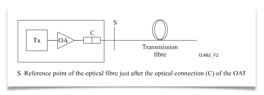
Scheme of insertion of an OAT
Applications and Configurations
The application of these OA devices can vary. For instance, a Power Amplifier (PA) might include an optical filter to minimize noise or separate signals in multiwavelength applications. The configurations can range from simple setups like Tx + PA + Rx to more complex arrangements like Tx + BA + LA + PA + Rx, as illustrated in the various schematics provided in the IEC standards.
Building upon the foundational knowledge of Optical Amplifiers (OAs), it’s essential to understand the practical configurations of these devices in optical networks. According to the definitions of Booster Amplifiers (BAs), Pre-amplifiers (PAs), and Line Amplifiers (LAs), and referencing Figure 1 from the IEC standards, we can explore various OA device applications and their configurations. These setups illustrate how OAs are integrated into optical communication systems, each serving a unique purpose in enhancing signal integrity and network performance.
- Tx + BA + Rx Configuration: This setup involves a transmitter (Tx), followed by a Booster Amplifier (BA), and then a receiver (Rx). The BA is used right after the transmitter to increase the signal power before it enters the long stretch of the fiber. This configuration is particularly useful in long-haul communication systems where maintaining a strong signal over vast distances is crucial.
- Tx + PA + Rx Configuration: Here, the system comprises a transmitter, followed by a Pre-amplifier (PA), and then a receiver. The PA is positioned close to the receiver to improve its sensitivity and to amplify the weakened incoming signal. This setup is ideal for scenarios where the incoming signal strength is low, and enhanced detection is required.
- Tx + LA + Rx Configuration: In this configuration, a Line Amplifier (LA) is placed between the transmitter and receiver. The LA’s role is to amplify the signal partway through the transmission path, effectively extending the reach of the communication link. This setup is common in both long-haul and regional networks.
- Tx + BA + PA + Rx Configuration: This more complex setup involves both a BA and a PA, with the BA placed after the transmitter and the PA before the receiver. This combination allows for both an initial boost in signal strength and a final amplification to enhance receiver sensitivity, making it suitable for extremely long-distance transmissions or when signals pass through multiple network segments.
- Tx + BA + LA + Rx Configuration: Combining a BA and an LA provides a powerful solution for extended reach. The BA boosts the signal post-transmission, and the LA offers additional amplification along the transmission path. This configuration is particularly effective in long-haul networks with significant attenuation.
- Tx + LA + PA + Rx Configuration: Here, the LA is used for mid-path amplification, while the PA is employed near the receiver. This setup ensures that the signal is sufficiently amplified both during transmission and before reception, which is vital in networks with long spans and higher signal loss.
- Tx + BA + LA + PA + Rx Configuration: This comprehensive setup includes a BA, an LA, and a PA, offering a robust solution for maintaining signal integrity across very long distances and complex network architectures. The BA boosts the initial signal strength, the LA provides necessary mid-path amplification, and the PA ensures that the receiver can effectively detect the signal.
Characteristics of Optical Amplifiers
Each type of OA has specific characteristics that define its performance in different applications, whether single-channel or multichannel. These characteristics include input and output power ranges, wavelength bands, noise figures, reflectance, and maximum tolerable reflectance at input and output, among others.
For instance, in single-channel applications, a Power Amplifier’s characteristics would include an input power range, output power range, power wavelength band, and signal-spontaneous noise figure. In contrast, for multichannel applications, additional parameters like channel allocation, channel input and output power ranges, and channel signal-spontaneous noise figure become relevant.
Optically Amplified Transmitters and Receivers
In the realm of OA subsystems like OATs and OARs, the focus shifts to parameters like bit rate, application code, operating signal wavelength range, and output power range for transmitters, and sensitivity, overload, and bit error ratio for receivers. These parameters are critical in defining the performance and suitability of these subsystems for specific applications.
Understanding Through Practical Examples
To illustrate, consider a scenario in a long-distance fiber optic communication system. Here, a Line Amplifier might be employed to extend the transmission distance. This amplifier would need to have a low noise figure to minimize signal degradation and a high saturation output power to ensure the signal remains strong over long distances. The specific values for these parameters would depend on the system’s requirements, such as the total transmission distance and the number of channels being used.
Advanced Applications of Optical Amplifiers
- Long-Haul Communication: In long-haul fiber optic networks, Line Amplifiers (LAs) play a critical role. They are strategically placed at intervals to compensate for signal loss. For example, an LA with a high saturation output power of around +17 dBm and a low noise figure, typically less than 5 dB, can significantly extend the reach of the communication link without the need for electronic regeneration.
- Submarine Cables: Submarine communication cables, spanning thousands of kilometers, heavily rely on Distributed Amplifiers, like Raman amplifiers. These amplifiers uniquely boost the signal directly within the fiber, offering a more distributed amplification approach, which is crucial for such extensive undersea networks.
- Metropolitan Area Networks: In shorter, more congested networks like those in metropolitan areas, a combination of Booster Amplifiers (BAs) and Pre-amplifiers can be used. A BA, with an output power range of up to +23 dBm, can effectively launch a strong signal into the network, while a Pre-amplifier at the receiving end, with a very low noise figure (as low as 4 dB), enhances the receiver’s sensitivity to weak signals.
- Optical Add-Drop Multiplexers (OADMs): In systems using OADMs for channel multiplexing and demultiplexing, Line Amplifiers help in maintaining signal strength across the channels. The ability to handle multiple channels, each potentially with different power levels, is crucial. Here, the channel addition/removal (steady-state) gain response and transient gain response become significant parameters.
Technological Innovations and Challenges
The development of OA technologies is not without challenges. One of the primary concerns is managing the noise, especially in systems with multiple amplifiers. Each amplification stage adds some noise, quantified by the signal-spontaneous noise figure, which can accumulate and degrade the overall signal quality.
Another challenge is the management of Polarization Mode Dispersion (PMD) in Line Amplifiers. PMD can cause different light polarizations to travel at slightly different speeds, leading to signal distortion. Modern LAs are designed to minimize PMD, a critical parameter in high-speed networks.
Future of Optical Amplifiers in Industry
The future of OAs is closely tied to the advancements in fiber optic technology. As data demands continue to skyrocket, the need for more efficient, higher-capacity networks grows. Optical Amplifiers will continue to evolve, with research focusing on higher power outputs, broader wavelength ranges, and more sophisticated noise management techniques.
Innovations like hybrid amplification techniques, combining the benefits of Raman and Erbium-Doped Fiber Amplifiers (EDFAs), are on the horizon. These hybrid systems aim to provide higher performance, especially in terms of power efficiency and noise reduction.
References
ITU-T :https://www.itu.int/en/ITU-T/Pages/default.aspx
Image :https://www.chinacablesbuy.com/guide-to-optical-amplifier.html


