Tag

Signal amplification

Browsing

In the world of fiber-optic communication, the integrity of the transmitted signal is critical. As an optical engineers, our primary objective is to mitigate the attenuation of signals across long distances, ensuring that data arrives at its destination with minimal loss and distortion. In this article we will discuss into the challenges of linear and nonlinear degradations in fiber-optic systems, with a focus on transoceanic length systems, and offers strategies for optimising system performance.

The Role of Optical Amplifiers

Erbium-doped fiber amplifiers (EDFAs) are the cornerstone of long-distance fiber-optic transmission, providing essential gain within the low-loss window around 1550 nm. Positioned typically between 50 to 100 km apart, these amplifiers are critical for compensating the fiber’s inherent attenuation. Despite their crucial role, EDFAs introduce additional noise, progressively degrading the optical signal-to-noise ratio (OSNR) along the transmission line. This degradation necessitates a careful balance between signal amplification and noise management to maintain transmission quality.

OSNR: The Critical Metric

The received OSNR, a key metric for assessing channel performance, is influenced by several factors, including the channel’s fiber launch power, span loss, and the noise figure (NF) of the EDFA. The relationship is outlined as follows:

osnrformula

Where:

  • is the number of EDFAs the signal has passed through.
  •  is the power of the signal when it’s first sent into the fiber, in dBm.
  • Loss represents the total loss the signal experiences, in dB.
  • NF is the noise figure of the EDFA, also in dB.

Increasing the launch power enhances the OSNR linearly; however, this is constrained by the onset of fiber nonlinearity, particularly Kerr effects, which limit the maximum effective launch power.

The Kerr Effect and Its Implications

The Kerr effect, stemming from the intensity-dependent refractive index of optical fiber, leads to modulation in the fiber’s refractive index and subsequent optical phase changes. Despite the Kerr coefficient () being exceedingly small, the combined effect of long transmission distances, high total power from EDFAs, and the small effective area of standard single-mode fiber (SMF) renders this nonlinearity a dominant factor in signal degradation over transoceanic distances.

The phase change induced by this effect depends on a few key factors:

  • The fiber’s nonlinear coefficient .
  • The signal power , which varies over time.
  • The transmission distance.
  • The fiber’s effective area .

kerr

This phase modulation complicates the accurate recovery of the transmitted optical field, thus limiting the achievable performance of undersea fiber-optic transmission systems.

The Kerr effect is a bit like trying to talk to someone at a party where the music volume keeps changing. Sometimes your message gets through loud and clear, and other times it’s garbled by the fluctuations. In fiber optics, managing these fluctuations is crucial for maintaining signal integrity over long distances.

Striking the Right Balance

Understanding and mitigating the effects of both linear and nonlinear degradations are critical for optimising the performance of undersea fiber-optic transmission systems. Engineers must navigate the delicate balance between maximizing OSNR for enhanced signal quality and minimising the impact of nonlinear distortions.The trick, then, is to find that sweet spot where our OSNR is high enough to ensure quality transmission but not so high that we’re deep into the realm of diminishing returns due to nonlinear degradation. Strategies such as carefully managing launch power, employing advanced modulation formats, and leveraging digital signal processing techniques are vital for overcoming these challenges.


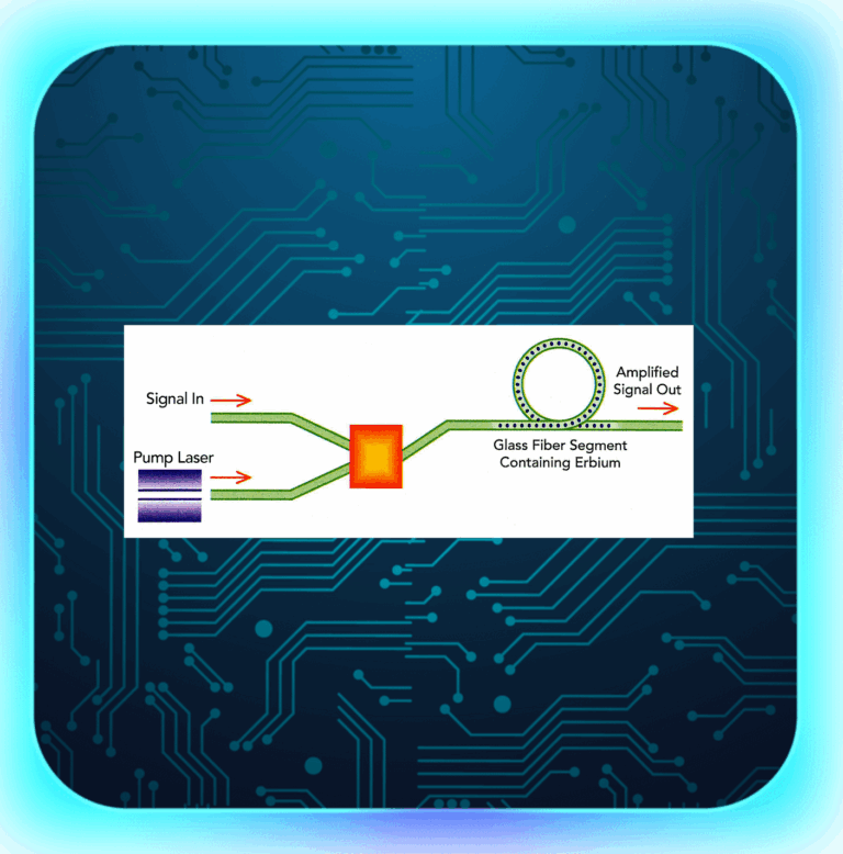
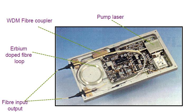
Optical Amplifiers (OAs) are key parts of today’s communication world. They help send data under the sea, land and even in space .In fact it is used in all electronic and telecommunications industry which has allowed human being develop and use gadgets and machines in daily routine.Due to OAs only; we are able to transmit data over a distance of few 100s too 1000s of kilometers.

Classification of OA Devices

Optical Amplifiers, integral in managing signal strength in fiber optics, are categorized based on their technology and application. These categories, as defined in ITU-T G.661, include Power Amplifiers (PAs), Pre-amplifiers, Line Amplifiers, OA Transmitter Subsystems (OATs), OA Receiver Subsystems (OARs), and Distributed Amplifiers.

amplifier

Scheme of insertion of an OA device

  1. Power Amplifiers (PAs): Positioned after the optical transmitter, PAs boost the signal power level. They are known for their high saturation power, making them ideal for strengthening outgoing signals.
  2. Pre-amplifiers: These are used before an optical receiver to enhance its sensitivity. Characterized by very low noise, they are crucial in improving signal reception.
  3. Line Amplifiers: Placed between passive fiber sections, Line Amplifiers are low noise OAs that extend the distance covered before signal regeneration is needed. They are particularly useful in point-multipoint connections in optical access networks.
  4. OA Transmitter Subsystems (OATs): An OAT integrates a power amplifier with an optical transmitter, resulting in a higher power transmitter.
  5. OA Receiver Subsystems (OARs): In OARs, a pre-amplifier is combined with an optical receiver, enhancing the receiver’s sensitivity.
  6. Distributed Amplifiers: These amplifiers, such as those using Raman pumping, provide amplification over an extended length of the optical fiber, distributing amplification across the transmission span.
Scheme of insertion of an OAT

Scheme of insertion of an OAT
Scheme of insertion of an OAR

Applications and Configurations

The application of these OA devices can vary. For instance, a Power Amplifier (PA) might include an optical filter to minimize noise or separate signals in multiwavelength applications. The configurations can range from simple setups like Tx + PA + Rx to more complex arrangements like Tx + BA + LA + PA + Rx, as illustrated in the various schematics provided in the IEC standards.

Building upon the foundational knowledge of Optical Amplifiers (OAs), it’s essential to understand the practical configurations of these devices in optical networks. According to the definitions of Booster Amplifiers (BAs), Pre-amplifiers (PAs), and Line Amplifiers (LAs), and referencing Figure 1 from the IEC standards, we can explore various OA device applications and their configurations. These setups illustrate how OAs are integrated into optical communication systems, each serving a unique purpose in enhancing signal integrity and network performance.

  1. Tx + BA + Rx Configuration: This setup involves a transmitter (Tx), followed by a Booster Amplifier (BA), and then a receiver (Rx). The BA is used right after the transmitter to increase the signal power before it enters the long stretch of the fiber. This configuration is particularly useful in long-haul communication systems where maintaining a strong signal over vast distances is crucial.
  2. Tx + PA + Rx Configuration: Here, the system comprises a transmitter, followed by a Pre-amplifier (PA), and then a receiver. The PA is positioned close to the receiver to improve its sensitivity and to amplify the weakened incoming signal. This setup is ideal for scenarios where the incoming signal strength is low, and enhanced detection is required.
  3. Tx + LA + Rx Configuration: In this configuration, a Line Amplifier (LA) is placed between the transmitter and receiver. The LA’s role is to amplify the signal partway through the transmission path, effectively extending the reach of the communication link. This setup is common in both long-haul and regional networks.
  4. Tx + BA + PA + Rx Configuration: This more complex setup involves both a BA and a PA, with the BA placed after the transmitter and the PA before the receiver. This combination allows for both an initial boost in signal strength and a final amplification to enhance receiver sensitivity, making it suitable for extremely long-distance transmissions or when signals pass through multiple network segments.
  5. Tx + BA + LA + Rx Configuration: Combining a BA and an LA provides a powerful solution for extended reach. The BA boosts the signal post-transmission, and the LA offers additional amplification along the transmission path. This configuration is particularly effective in long-haul networks with significant attenuation.
  6. Tx + LA + PA + Rx Configuration: Here, the LA is used for mid-path amplification, while the PA is employed near the receiver. This setup ensures that the signal is sufficiently amplified both during transmission and before reception, which is vital in networks with long spans and higher signal loss.
  7. Tx + BA + LA + PA + Rx Configuration: This comprehensive setup includes a BA, an LA, and a PA, offering a robust solution for maintaining signal integrity across very long distances and complex network architectures. The BA boosts the initial signal strength, the LA provides necessary mid-path amplification, and the PA ensures that the receiver can effectively detect the signal.

Characteristics of Optical Amplifiers

Each type of OA has specific characteristics that define its performance in different applications, whether single-channel or multichannel. These characteristics include input and output power ranges, wavelength bands, noise figures, reflectance, and maximum tolerable reflectance at input and output, among others.

For instance, in single-channel applications, a Power Amplifier’s characteristics would include an input power range, output power range, power wavelength band, and signal-spontaneous noise figure. In contrast, for multichannel applications, additional parameters like channel allocation, channel input and output power ranges, and channel signal-spontaneous noise figure become relevant.

Optically Amplified Transmitters and Receivers

In the realm of OA subsystems like OATs and OARs, the focus shifts to parameters like bit rate, application code, operating signal wavelength range, and output power range for transmitters, and sensitivity, overload, and bit error ratio for receivers. These parameters are critical in defining the performance and suitability of these subsystems for specific applications.

Understanding Through Practical Examples

To illustrate, consider a scenario in a long-distance fiber optic communication system. Here, a Line Amplifier might be employed to extend the transmission distance. This amplifier would need to have a low noise figure to minimize signal degradation and a high saturation output power to ensure the signal remains strong over long distances. The specific values for these parameters would depend on the system’s requirements, such as the total transmission distance and the number of channels being used.

Advanced Applications of Optical Amplifiers

  1. Long-Haul Communication: In long-haul fiber optic networks, Line Amplifiers (LAs) play a critical role. They are strategically placed at intervals to compensate for signal loss. For example, an LA with a high saturation output power of around +17 dBm and a low noise figure, typically less than 5 dB, can significantly extend the reach of the communication link without the need for electronic regeneration.
  2. Submarine Cables: Submarine communication cables, spanning thousands of kilometers, heavily rely on Distributed Amplifiers, like Raman amplifiers. These amplifiers uniquely boost the signal directly within the fiber, offering a more distributed amplification approach, which is crucial for such extensive undersea networks.
  3. Metropolitan Area Networks: In shorter, more congested networks like those in metropolitan areas, a combination of Booster Amplifiers (BAs) and Pre-amplifiers can be used. A BA, with an output power range of up to +23 dBm, can effectively launch a strong signal into the network, while a Pre-amplifier at the receiving end, with a very low noise figure (as low as 4 dB), enhances the receiver’s sensitivity to weak signals.
  4. Optical Add-Drop Multiplexers (OADMs): In systems using OADMs for channel multiplexing and demultiplexing, Line Amplifiers help in maintaining signal strength across the channels. The ability to handle multiple channels, each potentially with different power levels, is crucial. Here, the channel addition/removal (steady-state) gain response and transient gain response become significant parameters.

Technological Innovations and Challenges

The development of OA technologies is not without challenges. One of the primary concerns is managing the noise, especially in systems with multiple amplifiers. Each amplification stage adds some noise, quantified by the signal-spontaneous noise figure, which can accumulate and degrade the overall signal quality.

Another challenge is the management of Polarization Mode Dispersion (PMD) in Line Amplifiers. PMD can cause different light polarizations to travel at slightly different speeds, leading to signal distortion. Modern LAs are designed to minimize PMD, a critical parameter in high-speed networks.

Future of Optical Amplifiers in Industry

The future of OAs is closely tied to the advancements in fiber optic technology. As data demands continue to skyrocket, the need for more efficient, higher-capacity networks grows. Optical Amplifiers will continue to evolve, with research focusing on higher power outputs, broader wavelength ranges, and more sophisticated noise management techniques.

Innovations like hybrid amplification techniques, combining the benefits of Raman and Erbium-Doped Fiber Amplifiers (EDFAs), are on the horizon. These hybrid systems aim to provide higher performance, especially in terms of power efficiency and noise reduction.

References

ITU-T :https://www.itu.int/en/ITU-T/Pages/default.aspx

Image :https://www.chinacablesbuy.com/guide-to-optical-amplifier.html

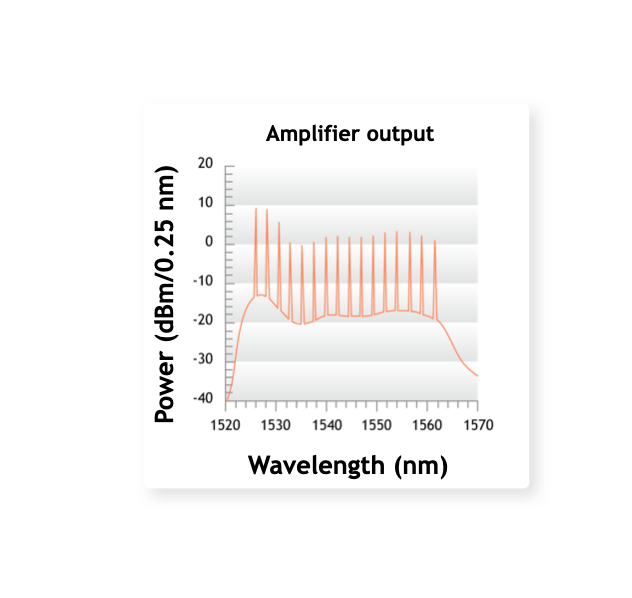
The main advantages and drawbacks of EDFAs are as follows.

Advantages

  • Commercially available in C band (1,530 to 1,565 nm) and L band (1,560 to 1,605) and up to  84-nm range at the laboratory stage.
  • Excellent coupling: The amplifier medium is an SM fiber;
  • Insensitivity to light polarization state;
  • Low sensitivity to temperature;
  • High gain: > 30 dB with gain flatness < ±0.8 dB and < ±0.5 dB in C and L band, respectively, in the scientific literature and in the manufacturer documentation
  • Low noise figure: 4.5 to 6 dB
  • No distortion at high bit rates;
  • Simultaneous amplification of wavelength division multiplexed signals;
  • Immunity to crosstalk among wavelength multiplexed channels (to a large extent)

Drawbacks

  • Pump laser necessary;
  • Difficult to integrate with other components;
  • Need to use a gain equalizer for multistage amplification;
  • Dropping channels can give rise to errors in surviving channels:dynamic control of amplifiers is  necessary.

A short discussion on 980nm and 1480nm pump based EDFA

Introduction

The 980nm pump needs three energy level for radiation while 1480nm pumps can excite the ions directly to the metastable level .edfa

(a) Energy level scheme of ground and first two excited states of Er ions in a silica matrix. The sublevel splitting and the lengths of arrows representing absorption and emission transitions are not drawn to scale. In the case of the 4 I11/2 state, s is the lifetime for nonradiative decay to the I13/2 first excited state and ssp is the spontaneous lifetime of the 4 I13/2 first excited state. (b) Absorption coefficient, a, and emission coefficient, g*, spectra for a typical aluminum co-doped EDF.

The most important feature of the level scheme is that the transition energy between the I15/2 ground state and the I13/2 first excited state corresponds to photon wavelengths (approximately 1530 to 1560 nm) for which the attenuation in silica fibers is lowest. Amplification is achieved by creating an inversion by pumping atoms into the first excited state, typically using either 980 nm or 1480 nm diode lasers. Because of the superior noise figure they provide and their superior wall plug efficiency, most EDFAs are built using 980 nm pump diodes. 1480 nm pump diodes are still often used in L-band EDFAs although here, too, 980 nm pumps are becoming more widely used.

Though pumping with 1480 nm is used and has an optical power conversion efficiency which is higher than that for 980 nm pumping, the latter is preferred because of the following advantages it has over 1480 nm pumping.

  • It provides a wider separation between the laser wavelength and pump wavelength.
  • 980 nm pumping gives less noise than 1480nm.
  • Unlike 1480 nm pumping, 980 nm pumping cannot stimulate back transition to the ground state.
  • 980 nm pumping also gives a higher signal gain, the maximum gain coefficient being 11 dB/mW against 6.3 dB/mW for the 1.48
  • The reason for better performance of 980 nm pumping over the 1.48 m pumping is related to the fact that the former has a narrower absorption spectrum.
  • The inversion factor almost becomes 1 in case of 980 nm pumping whereas for 1480 nm pumping the best one gets is about 1.6.
  • Quantum mechanics puts a lower limit of 3 dB to the optical noise figure at high optical gain. 980 nm pimping provides a value of 3.1 dB, close to the quantum limit whereas 1.48  pumping gives a value of 4.2 dB.
  • 1480nm pump needs more electrical power compare to 980nm.

Application

The 980 nm pumps EDFA’s are widely used in terrestrial systems while 1480nm pumps are used as Remote Optically Pumped Amplifiers (ROPA) in subsea links where it is difficult to put amplifiers.For submarine systems, remote pumping can be used in order not to have to electrically feed the amplifiers and remove electronic parts.Nowadays ,this is used in pumping up to 200km.

The erbium-doped fiber can be activated by a pump wavelength of 980 or 1480 nm but only the second one is used in repeaterless systems due to the lower fiber loss at 1.48 mm with respect to the loss at 0.98 mm. This allows the distance between the terminal and the remote amplifier to be increased.

In a typical configuration, the ROPA is comprised of a simple short length of erbium doped fiber in the transmission line placed a few tens of kilometers before a shore terminal or a conventional in-line EDFA. The remote EDF is backward pumped by a 1480 nm laser, from the terminal or in-line EDFA, thus providing signal gain

Vendors

Following are the vendors that manufactures 980nm and 1480nm EDFAs