
When we’re dealing with Optical Network Elements (ONEs) that include optical amplifiers, it’s important to note a key change in signal quality. Specifically, the Optical Signal-to-Noise Ratio (OSNR) at the points where the signal exits the system or at drop ports, is typically not as high as the OSNR where the signal enters or is added to the system. This decrease in signal quality is a critical factor to consider, and there’s a specific equation that allows us to quantify this reduction in OSNR. By using following equations, network engineers can effectively calculate and predict the change in OSNR, ensuring that the network’s performance meets the necessary standards.
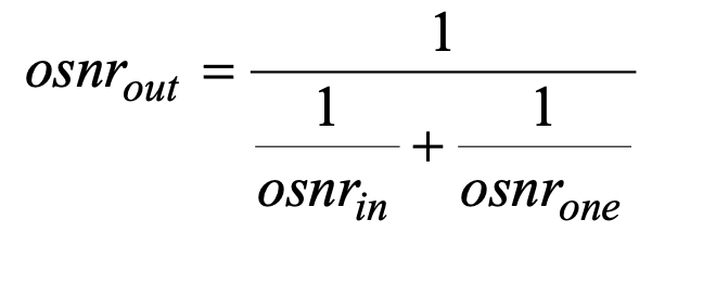
Where:
osnrout : linear OSNR at the output port of the ONE
osnrin : linear OSNR at the input port of the ONE
osnrone : linear OSNR that would appear at the output port of the ONE for a noise free input signal
If the OSNR is defined in logarithmic terms (dB) and the equation(Eq.1) for the OSNR due to the ONE being considered is substituted this equation becomes:
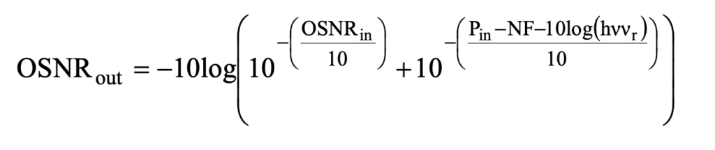
Where:
OSNRout : log OSNR (dB) at the output port of the ONE
OSNRin : log OSNR (dB) at the input port of the ONE
Pin : channel power (dBm) at the input port of the ONE
NF : noise figure (dB) of the relevant path through the ONE
h : Planck’s constant (in mJ•s to be consistent with in Pin (dBm))
v : optical frequency in Hz
vr : reference bandwidth in Hz (usually the frequency equivalent of 0.1 nm)
So if it needs to generalised the equation of an end to end point to point link, the equation can be written as
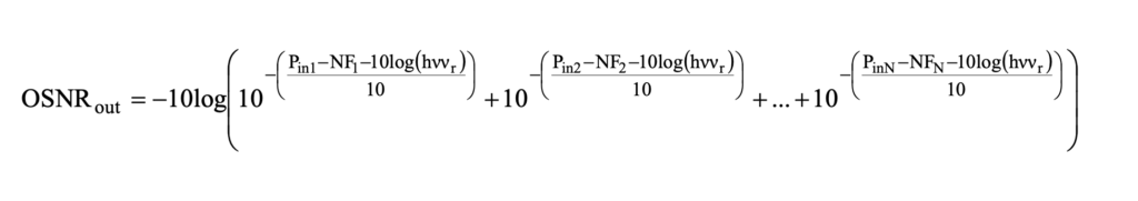
Where:
Pin1, Pin2 to PinN : channel powers (dBm) at the inputs of the amplifiers or ONEs on the relevant path through the network
NF1, NF2 to NFN : noise figures (dB) of the amplifiers or ONEs on the relevant path through the network
The required OSNRout value that is needed to meet the required system BER depends on many factors such as the bit rate, whether and what type of FEC is employed, the magnitude of any crosstalk or non-linear penalties in the DWDM line segments etc.Furthermore it will be discuss in another article.
Ref:
ITU-T G.680


