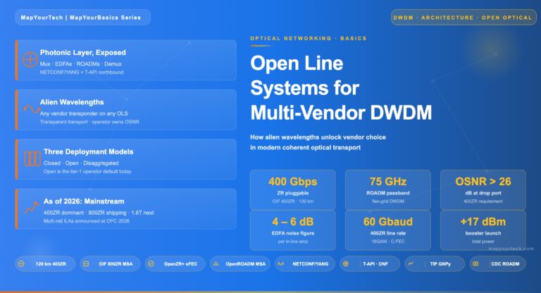
Tag

OSNR

Browsing

In the world of fiber-optic communication, the integrity of the transmitted signal is critical. As an optical engineers, our primary objective is to mitigate the attenuation of signals across long distances, ensuring that data arrives at its destination with minimal loss and distortion. In this article we will discuss into the challenges of linear and nonlinear degradations in fiber-optic systems, with a focus on transoceanic length systems, and offers strategies for optimising system performance.

The Role of Optical Amplifiers

Erbium-doped fiber amplifiers (EDFAs) are the cornerstone of long-distance fiber-optic transmission, providing essential gain within the low-loss window around 1550 nm. Positioned typically between 50 to 100 km apart, these amplifiers are critical for compensating the fiber’s inherent attenuation. Despite their crucial role, EDFAs introduce additional noise, progressively degrading the optical signal-to-noise ratio (OSNR) along the transmission line. This degradation necessitates a careful balance between signal amplification and noise management to maintain transmission quality.

OSNR: The Critical Metric

The received OSNR, a key metric for assessing channel performance, is influenced by several factors, including the channel’s fiber launch power, span loss, and the noise figure (NF) of the EDFA. The relationship is outlined as follows:

osnrformula

Where:

  • is the number of EDFAs the signal has passed through.
  •  is the power of the signal when it’s first sent into the fiber, in dBm.
  • Loss represents the total loss the signal experiences, in dB.
  • NF is the noise figure of the EDFA, also in dB.

Increasing the launch power enhances the OSNR linearly; however, this is constrained by the onset of fiber nonlinearity, particularly Kerr effects, which limit the maximum effective launch power.

The Kerr Effect and Its Implications

The Kerr effect, stemming from the intensity-dependent refractive index of optical fiber, leads to modulation in the fiber’s refractive index and subsequent optical phase changes. Despite the Kerr coefficient () being exceedingly small, the combined effect of long transmission distances, high total power from EDFAs, and the small effective area of standard single-mode fiber (SMF) renders this nonlinearity a dominant factor in signal degradation over transoceanic distances.

The phase change induced by this effect depends on a few key factors:

  • The fiber’s nonlinear coefficient .
  • The signal power , which varies over time.
  • The transmission distance.
  • The fiber’s effective area .

kerr

This phase modulation complicates the accurate recovery of the transmitted optical field, thus limiting the achievable performance of undersea fiber-optic transmission systems.

The Kerr effect is a bit like trying to talk to someone at a party where the music volume keeps changing. Sometimes your message gets through loud and clear, and other times it’s garbled by the fluctuations. In fiber optics, managing these fluctuations is crucial for maintaining signal integrity over long distances.

Striking the Right Balance

Understanding and mitigating the effects of both linear and nonlinear degradations are critical for optimising the performance of undersea fiber-optic transmission systems. Engineers must navigate the delicate balance between maximizing OSNR for enhanced signal quality and minimising the impact of nonlinear distortions.The trick, then, is to find that sweet spot where our OSNR is high enough to ensure quality transmission but not so high that we’re deep into the realm of diminishing returns due to nonlinear degradation. Strategies such as carefully managing launch power, employing advanced modulation formats, and leveraging digital signal processing techniques are vital for overcoming these challenges.


In this ever-evolving landscape of optical networking, the development of coherent optical standards, such as 400G ZR and ZR+, represents a significant leap forward in addressing the insatiable demand for bandwidth, efficiency, and scalability in data centers and network infrastructure. This technical blog delves into the nuances of these standards, comparing their features, applications, and how they are shaping the future of high-capacity networking.

Introduction to 400G ZR

The 400G ZR standard, defined by the Optical Internetworking Forum (OIF), is a pivotal development in the realm of optical networking, setting the stage for the next generation of data transmission over optical fiber’s. It is designed to facilitate the transfer of 400 Gigabit Ethernet over single-mode fiber across distances of up to 120 kilometers without the need for signal amplification or regeneration. This is achieved through the use of advanced modulation techniques like DP-16QAM and state-of-the-art forward error correction (FEC).

Key features of 400G ZR include:

  • High Capacity: Supports the transmission of 400 Gbps using a single wavelength.
  • Compact Form-Factor: Integrates into QSFP-DD and OSFP modules, aligning with industry standards for data center equipment.
  • Cost Efficiency: Reduces the need for external transponders and simplifies network architecture, lowering both CAPEX and OPEX.

Emergence of 400G ZR+

Building upon the foundation set by 400G ZR, the 400G ZR+ standard extends the capabilities of its predecessor by increasing the transmission reach and introducing flexibility in modulation schemes to cater to a broader range of network topologies and distances. The OpenZR+ MSA has been instrumental in this expansion, promoting interoperability and open standards in coherent optics.

Key enhancements in 400G ZR+ include:

  • Extended Reach: With advanced FEC and modulation, ZR+ can support links up to 2,000 km, making it suitable for longer metro, regional, and even long-haul deployments.
  • Versatile Modulation: Offers multiple configuration options (e.g., DP-16QAM, DP-8QAM, DP-QPSK), enabling operators to balance speed, reach, and optical performance.
  • Improved Power Efficiency: Despite its extended capabilities, ZR+ maintains a focus on energy efficiency, crucial for reducing the environmental impact of expanding network infrastructures.

ZR vs. ZR+: A Comparative Analysis

Feature. 400G ZR 400G ZR+
Reach Up to 120 km Up to 2,000 km
Modulation DP-16QAM DP-16QAM, DP-8QAM, DP-QPSK
Form Factor QSFP-DD, OSFP QSFP-DD, OSFP
Application Data center interconnects Metro, regional, long-haul

Adding few more interesting table for readersZR

The Future Outlook

The advent of 400G ZR and ZR+ is not just a technical upgrade; it’s a paradigm shift in how we approach optical networking. With these technologies, network operators can now deploy more flexible, efficient, and scalable networks, ready to meet the future demands of data transmission.

Moreover, the ongoing development and expected introduction of XR optics highlight the industry’s commitment to pushing the boundaries of what’s possible in optical networking. XR optics, with its promise of multipoint capabilities and aggregation of lower-speed interfaces, signifies the next frontier in coherent optical technology.

When we’re dealing with Optical Network Elements (ONEs) that include optical amplifiers, it’s important to note a key change in signal quality. Specifically, the Optical Signal-to-Noise Ratio (OSNR) at the points where the signal exits the system or at drop ports, is typically not as high as the OSNR where the signal enters or is added to the system. This decrease in signal quality is a critical factor to consider, and there’s a specific equation that allows us to quantify this reduction in OSNR. By using following equations, network engineers can effectively calculate and predict the change in OSNR, ensuring that the network’s performance meets the necessary standards.

Eq. 1
Eq.1

Where:

osnrout : linear OSNR at the output port of the ONE

osnrin : linear OSNR at the input port of the ONE

osnrone : linear OSNR that would appear at the output port of the ONE for a noise free input signal

If the OSNR is defined in logarithmic terms (dB) and the equation(Eq.1) for the OSNR due to the ONE being considered is substituted this equation becomes:

Eq.2

Where:

 OSNRout : log OSNR (dB) at the output port of the ONE

OSNRin : log OSNR (dB) at the input port of the ONE

 Pin : channel power (dBm) at the input port of the ONE

NF : noise figure (dB) of the relevant path through the ONE

h : Planck’s constant (in mJ•s to be consistent with in Pin (dBm))

v : optical frequency in Hz

vr : reference bandwidth in Hz (usually the frequency equivalent of 0.1 nm)

So if it needs to generalised the equation of an end to end point to point link, the equation can be written as

Eq.3

Where:

Pin1, Pin2 to PinN :  channel powers (dBm) at the inputs of the amplifiers or ONEs on the   relevant path through the network

NF1, NF2 to NFN : noise figures (dB) of the amplifiers or ONEs on the relevant path through the network

The required OSNRout value that is needed to meet the required system BER depends on many factors such as the bit rate, whether and what type of FEC is employed, the magnitude of any crosstalk or non-linear penalties in the DWDM line segments etc.Furthermore it will be discuss in another article.

Ref:

ITU-T G.680

Optical networks are the backbone of the internet, carrying vast amounts of data over great distances at the speed of light. However, maintaining signal quality over long fiber runs is a challenge due to a phenomenon known as noise concatenation. Let’s delve into how amplified spontaneous emission (ASE) noise affects Optical Signal-to-Noise Ratio (OSNR) and the performance of optical amplifier chains.

The Challenge of ASE Noise

ASE noise is an inherent byproduct of optical amplification, generated by the spontaneous emission of photons within an optical amplifier. As an optical signal traverses through a chain of amplifiers, ASE noise accumulates, degrading the OSNR with each subsequent amplifier in the chain. This degradation is a crucial consideration in designing long-haul optical transmission systems.

Understanding OSNR

OSNR measures the ratio of signal power to ASE noise power and is a critical parameter for assessing the performance of optical amplifiers. A high OSNR indicates a clean signal with low noise levels, which is vital for ensuring data integrity.

Reference System for OSNR Estimation

As depicted in Figure below), a typical multichannel N span system includes a booster amplifier, N−1 line amplifiers, and a preamplifier. To simplify the estimation of OSNR at the receiver’s input, we make a few assumptions:

Representation of optical line system interfaces (a multichannel N-span system)
  • All optical amplifiers, including the booster and preamplifier, have the same noise figure.
  • The losses of all spans are equal, and thus, the gain of the line amplifiers compensates exactly for the loss.
  • The output powers of the booster and line amplifiers are identical.

Estimating OSNR in a Cascaded System

E1: Master Equation For OSNR

E1: Master Equation For OSNR

Pout is the output power (per channel) of the booster and line amplifiers in dBm, L is the span loss in dB (which is assumed to be equal to the gain of the line amplifiers), GBA is the gain of the optical booster amplifier in dB, NFis the signal-spontaneous noise figure of the optical amplifier in dB, h is Planck’s constant (in mJ·s to be consistent with Pout in dBm), ν is the optical frequency in Hz, νr is the reference bandwidth in Hz (corresponding to c/Br ), N–1 is the total number of line amplifiers.

The OSNR at the receivers can be approximated by considering the output power of the amplifiers, the span loss, the gain of the optical booster amplifier, and the noise figure of the amplifiers. Using constants such as Planck’s constant and the optical frequency, we can derive an equation that sums the ASE noise contributions from all N+1 amplifiers in the chain.

Simplifying the Equation

Under certain conditions, the OSNR equation can be simplified. If the booster amplifier’s gain is similar to that of the line amplifiers, or if the span loss greatly exceeds the booster gain, the equation can be modified to reflect these scenarios. These simplifications help network designers estimate OSNR without complex calculations.

1)          If the gain of the booster amplifier is approximately the same as that of the line amplifiers, i.e., GBA » L, above Equation E1 can be simplified to:

osnr_2

E1-1

2)          The ASE noise from the booster amplifier can be ignored only if the span loss L (resp. the gain of the line amplifier) is much greater than the booster gain GBA. In this case Equation E1-1 can be simplified to:

E1-2

3)          Equation E1-1 is also valid in the case of a single span with only a booster amplifier, e.g., short‑haul multichannel IrDI in Figure 5-5 of [ITU-T G.959.1], in which case it can be modified to:

E1-3

4)          In case of a single span with only a preamplifier, Equation E1 can be modified to:

Practical Implications for Network Design

Understanding the accumulation of ASE noise and its impact on OSNR is crucial for designing reliable optical networks. It informs decisions on amplifier placement, the necessity of signal regeneration, and the overall system architecture. For instance, in a system where the span loss is significantly high, the impact of the booster amplifier on ASE noise may be negligible, allowing for a different design approach.

Conclusion

Noise concatenation is a critical factor in the design and operation of optical networks. By accurately estimating and managing OSNR, network operators can ensure signal quality, minimize error rates, and extend the reach of their optical networks.

In a landscape where data demands are ever-increasing, mastering the intricacies of noise concatenation and OSNR is essential for anyone involved in the design and deployment of optical communication systems.

References

https://www.itu.int/rec/T-REC-G/e

As communication networks become increasingly dependent on fiber-optic technology, it is essential to understand the quality of the signal in optical links. The two primary parameters used to evaluate the signal quality are Optical Signal-to-Noise Ratio (OSNR) and Q-factor. In this article, we will explore what OSNR and Q-factor are and how they are interdependent with examples for optical link.

Table of Contents

  1. Introduction
  2. What is OSNR?
    • Definition and Calculation of OSNR
  3. What is Q-factor?
    • Definition and Calculation of Q-factor
  4. OSNR and Q-factor Relationship
  5. Examples of OSNR and Q-factor Interdependency
    • Example 1: OSNR and Q-factor for Single Wavelength System
    • Example 2: OSNR and Q-factor for Multi-Wavelength System
  6. Conclusion
  7. FAQs

1. Introduction

Fiber-optic technology is the backbone of modern communication systems, providing fast, secure, and reliable transmission of data over long distances. However, the signal quality of an optical link is subject to various impairments, such as attenuation, dispersion, and noise. To evaluate the signal quality, two primary parameters are used – OSNR and Q-factor.

In this article, we will discuss what OSNR and Q-factor are, how they are calculated, and their interdependency in optical links. We will also provide examples to help you understand how the OSNR and Q-factor affect optical links.

2. What is OSNR?

OSNR stands for Optical Signal-to-Noise Ratio. It is a measure of the signal quality of an optical link, indicating how much the signal power exceeds the noise power. The higher the OSNR value, the better the signal quality of the optical link.

Definition and Calculation of OSNR

The OSNR is calculated as the ratio of the optical signal power to the noise power within a specific bandwidth. The formula for calculating OSNR is as follows:

OSNR (dB) = 10 log10 (Signal Power / Noise Power)

3. What is Q-factor?

Q-factor is a measure of the quality of a digital signal in an optical communication system. It is a function of the bit error rate (BER), signal power, and noise power. The higher the Q-factor value, the better the quality of the signal.

Definition and Calculation of Q-factor

The Q-factor is calculated as the ratio of the distance between the average signal levels of two adjacent symbols to the standard deviation of the noise. The formula for calculating Q-factor is as follows:

Q-factor = (Signal Level 1 – Signal Level 2) / Noise RMS

4. OSNR and Q-factor Relationship

OSNR and Q-factor are interdependent parameters, meaning that changes in one parameter affect the other. The relationship between OSNR and Q-factor is a logarithmic one, which means that a small change in the OSNR can lead to a significant change in the Q-factor.

Generally, the Q-factor increases as the OSNR increases, indicating a better signal quality. However, at high OSNR values, the Q-factor reaches a saturation point, and further increase in the OSNR does not improve the Q-factor.

5. Examples of OSNR and Q-factor Interdependency

Example 1: OSNR and Q-factor for Single Wavelength System

In a single wavelength system, the OSNR and Q-factor have a direct relationship. An increase in the OSNR improves the Q-factor, resulting in a better signal quality. For instance, if the OSNR of a single wavelength system increases from 20 dB to 30 dB,

the Q-factor also increases, resulting in a lower BER and better signal quality. Conversely, a decrease in the OSNR degrades the Q-factor, leading to a higher BER and poor signal quality.

Example 2: OSNR and Q-factor for Multi-Wavelength System

In a multi-wavelength system, the interdependence of OSNR and Q-factor is more complex. The OSNR and Q-factor of each wavelength in the system can vary independently, and the overall system performance depends on the worst-performing wavelength.

For example, consider a four-wavelength system, where each wavelength has an OSNR of 20 dB, 25 dB, 30 dB, and 35 dB. The Q-factor of each wavelength will be different due to the different noise levels. The overall system performance will depend on the wavelength with the worst Q-factor. In this case, if the Q-factor of the first wavelength is the worst, the system performance will be limited by the Q-factor of that wavelength, regardless of the OSNR values of the other wavelengths.

6. Conclusion

In conclusion, OSNR and Q-factor are essential parameters used to evaluate the signal quality of an optical link. They are interdependent, and changes in one parameter affect the other. Generally, an increase in the OSNR improves the Q-factor and signal quality, while a decrease in the OSNR degrades the Q-factor and signal quality. However, the relationship between OSNR and Q-factor is more complex in multi-wavelength systems, and the overall system performance depends on the worst-performing wavelength.

Understanding the interdependence of OSNR and Q-factor is crucial in designing and optimizing optical communication systems for better performance.

7. FAQs

  1. What is the difference between OSNR and SNR? OSNR is the ratio of signal power to noise power within a specific bandwidth, while SNR is the ratio of signal power to noise power over the entire frequency range.
  2. What is the acceptable range of OSNR and Q-factor in optical communication systems? The acceptable range of OSNR and Q-factor varies depending on the specific application and system design. However, a higher OSNR and Q-factor generally indicate better signal quality.
  3. How can I improve the OSNR and Q-factor of an optical link? You can improve the OSNR and Q-factor of an optical link by reducing noise sources, optimizing system design, and using higher-quality components.
  4. Can I measure the OSNR and Q-factor of an optical link in real-time? Yes, you can measure the OSNR and Q-factor of an optical link in real-time using specialized instruments such as an optical spectrum analyzer and a bit error rate tester.
  5. What are the future trends in optical communication systems regarding OSNR and Q-factor? Future trends in optical communication systems include the development of advanced modulation techniques and the use of machine learning algorithms to optimize system performance and improve the OSNR and Q-factor of optical links.

In this article, we explore whether OSNR (Optical Signal-to-Noise Ratio) depends on data rate or modulation in DWDM (Dense Wavelength Division Multiplexing) link. We delve into the technicalities and provide a comprehensive overview of this important topic.

Introduction

OSNR is a crucial parameter in optical communication systems that determines the quality of the optical signal. It measures the ratio of the signal power to the noise power in a given bandwidth. The higher the OSNR value, the better the signal quality and the more reliable the communication link.

DWDM technology is widely used in optical communication systems to increase the capacity of fiber optic networks. It allows multiple optical signals to be transmitted over a single fiber by using different wavelengths of light. However, as the number of wavelengths and data rates increase, the OSNR value may decrease, which can lead to signal degradation and errors.

In this article, we aim to answer the question of whether OSNR depends on data rate or modulation in DWDM link. We will explore the technical aspects of this topic and provide a comprehensive overview to help readers understand this important parameter.

Does OSNR Depend on Data Rate?

The data rate is the amount of data that can be transmitted per unit time, usually measured in bits per second (bps). In DWDM systems, the data rate can vary depending on the modulation scheme and the number of wavelengths used. The higher the data rate, the more information can be transmitted over the network.

One might assume that the OSNR value would decrease as the data rate increases. This is because a higher data rate requires a larger bandwidth, which means more noise is present in the signal. However, this assumption is not entirely correct.

In fact, the OSNR value depends on the signal bandwidth, not the data rate. The bandwidth of the signal is determined by the modulation scheme used. For example, a higher-order modulation scheme, such as QPSK (Quadrature Phase-Shift Keying), has a narrower bandwidth than a lower-order modulation scheme, such as BPSK (Binary Phase-Shift Keying).

Therefore, the OSNR value is not directly dependent on the data rate, but rather on the modulation scheme used to transmit the data. In other words, a higher data rate can be achieved with a narrower bandwidth by using a higher-order modulation scheme, which can maintain a high OSNR value.

Does OSNR Depend on Modulation?

As mentioned earlier, the OSNR value depends on the signal bandwidth, which is determined by the modulation scheme used. Therefore, the OSNR value is directly dependent on the modulation scheme used in the DWDM system.

The modulation scheme determines how the data is encoded onto the optical signal. There are several modulation schemes used in optical communication systems, including BPSK, QPSK, 8PSK (8-Phase-Shift Keying), and 16QAM (16-Quadrature Amplitude Modulation).

In general, higher-order modulation schemes have a higher data rate but a narrower bandwidth, which means they can maintain a higher OSNR value. However, higher-order modulation schemes are also more susceptible to noise and other impairments in the communication link.

Therefore, the choice of modulation scheme depends on the specific requirements of the communication system. If a high data rate is required, a higher-order modulation scheme can be used, but the OSNR value may decrease. On the other hand, if a high OSNR value is required, a lower-order modulation scheme can be used, but the data rate may be lower.

Pros and Cons of Different Modulation Schemes

Different modulation schemes have their own advantages and disadvantages, which must be considered when choosing a scheme for a particular communication system.

BPSK (Binary Phase-Shift Keying)

BPSK is a simple modulation scheme that encodes data onto a carrier wave by shifting the phase of the wave by 180 degrees for a “1” bit and leaving it unchanged for a “0” bit. BPSK has a relatively low data rate but is less susceptible to noise and other impairments in the communication link.

Pros:

  • Simple modulation scheme
  • Low susceptibility to noise

Cons:

  • Low data rate
  • Narrow bandwidth

QPSK (Quadrature Phase-Shift Keying)

QPSK is a more complex modulation scheme that encodes data onto a carrier wave by shifting the phase of the wave by 90, 180, 270, or 0 degrees for each symbol. QPSK has a higher data rate than BPSK but is more susceptible to noise and other impairments in the communication link.

Pros:

  • Higher data rate than BPSK
  • More efficient use of bandwidth

Cons:

  • More susceptible to noise than BPSK

8PSK (8-Phase-Shift Keying)

8PSK is a higher-order modulation scheme that encodes data onto a carrier wave by shifting the phase of the wave by 45, 90, 135, 180, 225, 270, 315, or 0 degrees for each symbol. 8PSK has a higher data rate than QPSK but is more susceptible to noise and other impairments in the communication link.

Pros:

  • Higher data rate than QPSK
  • More efficient use of bandwidth

Cons:

  • More susceptible to noise than QPSK

16QAM (16-Quadrature Amplitude Modulation)

16QAM is a high-order modulation scheme that encodes data onto a carrier wave by modulating the amplitude and phase of the wave. 16QAM has a higher data rate than 8PSK but is more susceptible to noise and other impairments in the communication link.

Pros:

  • Highest data rate of all modulation schemes
  • More efficient use of bandwidth

Cons:

  • Most susceptible to noise and other impairments

Conclusion

In conclusion, the OSNR value in a DWDM link depends on the modulation scheme used and the signal bandwidth, rather than the data rate. Higher-order modulation schemes have a higher data rate but a narrower bandwidth, which can result in a lower OSNR value. Lower-order modulation schemes have a wider bandwidth, which can result in a higher OSNR value but a lower data rate.

Therefore, the choice of modulation scheme depends on the specific requirements of the communication system. If a high data rate is required, a higher-order modulation scheme can be used, but the OSNR value may decrease. On the other hand, if a high OSNR value is required, a lower-order modulation scheme can be used, but the data rate may be lower.

Ultimately, the selection of the appropriate modulation scheme and other parameters in a DWDM link requires careful consideration of the specific application and requirements of the communication system.

As we move towards a more connected world, the demand for faster and more reliable communication networks is increasing. Optical communication systems are becoming the backbone of these networks, enabling high-speed data transfer over long distances. One of the key parameters that determine the performance of these systems is the Optical Signal-to-Noise Ratio (OSNR) and Q factor values. In this article, we will explore the OSNR values and Q factor values for various data rates and modulations, and how they impact the performance of optical communication systems.

General use table for reference

osnr_ber_q.png

What is OSNR?

OSNR is the ratio of the optical signal power to the noise power in a given bandwidth. It is a measure of the signal quality and represents the signal-to-noise ratio at the receiver. OSNR is usually expressed in decibels (dB) and is calculated using the following formula:

OSNR = 10 log (Signal Power / Noise Power)

Higher OSNR values indicate a better quality signal, as the signal power is stronger than the noise power. In optical communication systems, OSNR is an important parameter that affects the bit error rate (BER), which is a measure of the number of errors in a given number of bits transmitted.

What is Q factor?

Q factor is a measure of the quality of a digital signal. It is a dimensionless number that represents the ratio of the signal power to the noise power, taking into account the spectral width of the signal. Q factor is usually expressed in decibels (dB) and is calculated using the following formula:

Q = 20 log (Signal Power / Noise Power)

Higher Q factor values indicate a better quality signal, as the signal power is stronger than the noise power. In optical communication systems, Q factor is an important parameter that affects the BER.

OSNR and Q factor for various data rates and modulations

The OSNR and Q factor values for a given data rate and modulation depend on several factors, such as the distance between the transmitter and receiver, the type of optical fiber used, and the type of amplifier used. In general, higher data rates and more complex modulations require higher OSNR and Q factor values for optimal performance.

Factors affecting OSNR and Q factor values

Several factors can affect the OSNR and Q factor values in optical communication systems. One of the key factors is the type of optical fiber used. Single-mode fibers have lower dispersion and attenuation compared to multi-mode fibers, which can result in higher OSNR and Q factor values. The type of amplifier used also plays a role, with erbium-doped fiber amplifiers

being the most commonly used type in optical communication systems. Another factor that can affect OSNR and Q factor values is the distance between the transmitter and receiver. Longer distances can result in higher attenuation, which can lower the OSNR and Q factor values.

Improving OSNR and Q factor values

There are several techniques that can be used to improve the OSNR and Q factor values in optical communication systems. One of the most commonly used techniques is to use optical amplifiers, which can boost the signal power and improve the OSNR and Q factor values. Another technique is to use optical filters, which can remove unwanted noise and improve the signal quality.

Conclusion

OSNR and Q factor values are important parameters that affect the performance of optical communication systems. Higher OSNR and Q factor values result in better signal quality and lower BER, which is essential for high-speed data transfer over long distances. By understanding the factors that affect OSNR and Q factor values, and by using the appropriate techniques to improve them, we can ensure that optical communication systems perform optimally and meet the growing demands of our connected world.

FAQs

  1. What is the difference between OSNR and Q factor?
  • OSNR is a measure of the signal-to-noise ratio, while Q factor is a measure of the signal quality taking into account the spectral width of the signal.
  1. What is the minimum OSNR and Q factor required for a 10 Gbps NRZ modulation?
  • The minimum OSNR required is 14 dB, and the minimum Q factor required is 7 dB.
  1. What factors can affect OSNR and Q factor values?
  • The type of optical fiber used, the type of amplifier used, and the distance between the transmitter and receiver can affect OSNR and Q factor values.
  1. How can OSNR and Q factor values be improved?
  • Optical amplifiers and filters can be used to improve OSNR and Q factor values.
  1. Why are higher OSNR and Q factor values important for optical communication systems?
  • Higher OSNR and Q factor values result in better signal quality and lower BER, which is essential for high-speed data transfer over long distances.
  1. What is a Raman amplifier?

A: A Raman amplifier is a type of optical amplifier that utilizes stimulated Raman scattering (SRS) to amplify optical signals in fiber-optic communication systems.

  1. How does a Raman amplifier work?

A: Raman amplification occurs when a high-power pump laser interacts with the optical signal in the transmission fiber, causing energy transfer from the pump wavelength to the signal wavelength through stimulated Raman scattering, thus amplifying the signal.

  1. What is the difference between a Raman amplifier and an erbium-doped fiber amplifier (EDFA)?

A: A Raman amplifier uses stimulated Raman scattering in the transmission fiber for amplification, while an EDFA uses erbium-doped fiber as the gain medium. Raman amplifiers can provide gain over a broader wavelength range and have lower noise compared to EDFAs.

  1. What are the advantages of Raman amplifiers?

A: Advantages of Raman amplifiers include broader gain bandwidth, lower noise, and better performance in combating nonlinear effects compared to other optical amplifiers, such as EDFAs.

  1. What is the typical gain bandwidth of a Raman amplifier?

A: The typical gain bandwidth of a Raman amplifier can be up to 100 nm or more, depending on the pump laser configuration and fiber properties.

  1. What are the key components of a Raman amplifier?

A: Key components of a Raman amplifier include high-power pump lasers, wavelength division multiplexers (WDMs) or couplers, and the transmission fiber itself, which serves as the gain medium.

  1. How do Raman amplifiers reduce nonlinear effects in optical networks?

A: Raman amplifiers can be configured to provide distributed gain along the transmission fiber, reducing the peak power of the optical signals and thus mitigating nonlinear effects such as self-phase modulation and cross-phase modulation.

  1. What are the different types of Raman amplifiers?

A: Raman amplifiers can be classified as discrete Raman amplifiers (DRAs) and distributed Raman amplifiers (DRAs). DRAs use a separate section of fiber as the gain medium, while DRAs provide gain directly within the transmission fiber.

  1. How is a Raman amplifier pump laser configured?

A: Raman amplifier pump lasers can be configured in various ways, such as co-propagating (pump and signal travel in the same direction) or counter-propagating (pump and signal travel in opposite directions) to optimize performance.

  1. What are the safety concerns related to Raman amplifiers?

A: The high-power pump lasers used in Raman amplifiers can pose safety risks, including damage to optical components and potential harm to technicians if proper safety precautions are not followed.

  1. Can Raman amplifiers be used in combination with other optical amplifiers?

A: Yes, Raman amplifiers can be used in combination with other optical amplifiers, such as EDFAs, to optimize system performance by leveraging the advantages of each amplifier type.

  1. How does the choice of fiber type impact Raman amplification?

A: The choice of fiber type can impact Raman amplification efficiency, as different fiber types exhibit varying Raman gain coefficients and effective area, which affect the gain and noise performance.

  1. What is the Raman gain coefficient?

A: The Raman gain coefficient is a measure of the efficiency of the Raman scattering process in a specific fiber. A higher Raman gain coefficient indicates more efficient energy transfer from the pump laser to the optical signal.

  1. What factors impact the performance of a Raman amplifier?

A: Factors impacting Raman amplifier performance include pump laser power and wavelength, fiber type and length, signal wavelength, and the presence of other nonlinear effects.

  1. How does temperature affect Raman amplifier performance?

A: Temperature can affect Raman amplifier performance by influencing the Raman gain coefficient and the efficiency of the stimulated Raman scattering process. Proper temperature management is essential for optimal Raman amplifier performance.

  1. What is the role of a Raman pump combiner?

A: A Raman pump combiner is a device used to combine the output of multiple high-power pump lasers, providing a single high-power pump source to optimize Raman amplifier performance.

  1. How does polarization mode dispersion (PMD) impact Raman amplifiers?

A: PMD can affect the performance of Raman amplifiers by causing variations in the gain and noise characteristics for different polarization states, potentially leading to signal degradation.

  1. How do Raman amplifiers impact optical signal-to-noise ratio (OSNR)?

A: Raman amplifiers can improve the OSNR by providing distributed gain along the transmission fiber and reducing the peak power of the optical signals, which helps to mitigate nonlinear effects and improve signal quality.

  1. What are the challenges in implementing Raman amplifiers?

A: Challenges in implementing Raman amplifiers include the need for high-power pump lasers, proper safety precautions, temperature management, and potential interactions with other nonlinear effects in the fiber-optic system.

  1. What is the future of Raman amplifiers in optical networks?

A: The future of Raman amplifiers in optical networks includes further research and development to optimize performance, reduce costs, and integrate Raman amplifiers with other emerging technologies, such as software-defined networking (SDN), to enable more intelligent and adaptive optical networks.

Discover the most effective OSNR improvement techniques to boost the quality and reliability of optical communication systems. Learn the basics, benefits, and practical applications of OSNR improvement techniques today!

Introduction:

Optical signal-to-noise ratio (OSNR) is a key performance parameter that measures the quality of an optical communication system. It is a critical factor that determines the capacity, reliability, and stability of optical networks. To ensure optimal OSNR performance, various OSNR improvement techniques have been developed and implemented in modern optical communication systems.

In this article, we will delve deeper into the world of OSNR improvement techniques and explore the most effective ways to boost OSNR and enhance the quality of optical communication systems. From basic concepts to practical applications, we will cover everything you need to know about OSNR improvement techniques and how they can benefit your business.

So, let’s get started!

OSNR Improvement Techniques: Basics and Benefits

What is OSNR, and Why Does it Matter?

OSNR is a measure of the signal quality of an optical communication system, which compares the power of the signal to the power of the noise in the system. In simple terms, it is a ratio of the signal power to the noise power. A higher OSNR indicates a better signal quality and a lower error rate, while a lower OSNR indicates a weaker signal and a higher error rate.

OSNR is a critical factor that determines the performance and reliability of optical communication systems. It affects the capacity, reach, and stability of the system, as well as the cost and complexity of the equipment. Therefore, maintaining optimal OSNR is essential for ensuring high-quality and efficient optical communication.

What are OSNR Improvement Techniques?

OSNR improvement techniques are a set of methods and technologies used to enhance the OSNR performance of optical communication systems. They aim to reduce the noise level in the system and increase the signal-to-noise ratio, thereby improving the quality and reliability of the system.

There are various OSNR improvement techniques available today, ranging from simple adjustments to advanced technologies. Some of the most common techniques include:

  1. Optical Amplification: This technique involves amplifying the optical signal to increase its power and improve its quality. It can be done using various types of amplifiers, such as erbium-doped fiber amplifiers (EDFAs), Raman amplifiers, and semiconductor optical amplifiers (SOAs).
  2. Dispersion Management: This technique involves managing the dispersion properties of the optical fiber to minimize the pulse spreading and reduce the noise in the system. It can be done using various dispersion compensation techniques, such as dispersion-compensating fibers (DCFs), dispersion-shifted fibers (DSFs), and chirped fiber Bragg gratings (CFBGs).
  3. Polarization Management: This technique involves managing the polarization properties of the optical signal to minimize the polarization-mode dispersion (PMD) and reduce the noise in the system. It can be done using various polarization-management techniques, such as polarization-maintaining fibers (PMFs), polarization controllers, and polarization splitters.
  4. Wavelength Management: This technique involves managing the wavelength properties of the optical signal to minimize the impact of wavelength-dependent losses and reduce the noise in the system. It can be done using various wavelength-management techniques, such as wavelength-division multiplexing (WDM), coarse wavelength-division multiplexing (CWDM), and dense wavelength-division multiplexing (DWDM).

What are the Benefits of OSNR Improvement Techniques?

OSNR improvement techniques offer numerous benefits for optical communication systems, including:

  1. Improved Signal Quality: OSNR improvement techniques can significantly improve the signal quality ofthe system, leading to a higher data transmission rate and a lower error rate.
    1. Increased System Reach: OSNR improvement techniques can extend the reach of the system by reducing the impact of noise and distortion on the signal.
    2. Enhanced System Stability: OSNR improvement techniques can improve the stability and reliability of the system by reducing the impact of environmental factors and system fluctuations on the signal.
    3. Reduced Cost and Complexity: OSNR improvement techniques can reduce the cost and complexity of the system by allowing the use of lower-power components and simpler architectures.

    Implementing OSNR Improvement Techniques: Best Practices

    Assessing OSNR Performance

    Before implementing OSNR improvement techniques, it is essential to assess the current OSNR performance of the system. This can be done using various OSNR measurement techniques, such as the optical spectrum analyzer (OSA), the optical time-domain reflectometer (OTDR), and the bit-error-rate tester (BERT).

    By analyzing the OSNR performance of the system, you can identify the areas that require improvement and determine the most appropriate OSNR improvement techniques to use.

    Selecting OSNR Improvement Techniques

    When selecting OSNR improvement techniques, it is essential to consider the specific requirements and limitations of the system. Some factors to consider include:

    1. System Type and Configuration: The OSNR improvement techniques used may vary depending on the type and configuration of the system, such as the transmission distance, data rate, and modulation format.
    2. Budget and Resources: The cost and availability of the OSNR improvement techniques may also affect the selection process.
    3. Compatibility and Interoperability: The OSNR improvement techniques used must be compatible with the existing system components and interoperable with other systems.
    4. Performance Requirements: The OSNR improvement techniques used must meet the performance requirements of the system, such as the minimum OSNR level and the maximum error rate.

    Implementing OSNR Improvement Techniques

    Once you have selected the most appropriate OSNR improvement techniques, it is time to implement them into the system. This may involve various steps, such as:

    1. Upgrading or Replacing Equipment: This may involve replacing or upgrading components such as amplifiers, filters, and fibers to improve the OSNR performance of the system.
    2. Optimizing System Settings: This may involve adjusting the system settings, such as the gain, the dispersion compensation, and the polarization control, to optimize the OSNR performance of the system.
    3. Testing and Validation: This may involve testing and validating the OSNR performance of the system after implementing the OSNR improvement techniques to ensure that the desired improvements have been achieved.

    FAQs About OSNR Improvement Techniques

    What is the minimum OSNR level required for optical communication systems?

    The minimum OSNR level required for optical communication systems may vary depending on the specific requirements of the system, such as the data rate, the transmission distance, and the modulation format. Generally, a minimum OSNR level of 20 dB is considered acceptable for most systems.

    How can OSNR improvement techniques affect the cost of optical communication systems?

    OSNR improvement techniques can affect the cost of optical communication systems by allowing the use of lower-power components and simpler architectures, thereby reducing the overall cost and complexity of the system.

    What are the most effective OSNR improvement techniques for long-distance optical communication?

    The most effective OSNR improvement techniques for long-distance optical communication may vary depending on the specific requirements and limitations of the system. Generally, dispersion compensation techniques, such as dispersion-compensating fibers (DCFs), and amplification techniques, such as erbium-doped fiber amplifiers (EDFAs), are effective for improving OSNR in long

    distance optical communication.

    Can OSNR improvement techniques be used in conjunction with other signal quality enhancement techniques?

    Yes, OSNR improvement techniques can be used in conjunction with other signal quality enhancement techniques, such as forward error correction (FEC), modulation schemes, and equalization techniques, to further improve the overall signal quality and reliability of the system.

    Conclusion

    OSNR improvement techniques are essential for ensuring high-quality and reliable optical communication systems. By understanding the basics, benefits, and best practices of OSNR improvement techniques, you can optimize the performance and efficiency of your system and stay ahead of the competition.

    Remember to assess the current OSNR performance of your system, select the most appropriate OSNR improvement techniques based on your specific requirements, and implement them into the system carefully and systematically. With the right OSNR improvement techniques, you can unlock the full potential of your optical communication system and achieve greater success in your business.

    So, what are you waiting for? Start exploring the world of OSNR improvement techniques today and experience the power of high-quality optical communication!

How does Tx power changes the OSNR and Q factor in optical link

In the world of fiber optic communication, the quality of a signal is of utmost importance. One of the parameters that determine the signal quality is the Tx power. The Tx power is the amount of optical power that is transmitted by the optical transmitter. In this article, we will discuss how the Tx power affects two important parameters, the OSNR and Q factor, in an optical link.

Understanding the concept of OSNR

OSNR, or optical signal-to-noise ratio, is a measure of the signal quality in an optical link. It is defined as the ratio of the optical signal power to the noise power. The higher the OSNR, the better the signal quality. OSNR is affected by various factors such as the quality of the components, the length of the fiber, and the Tx power.

Relationship between Tx power and OSNR

The Tx power has a direct impact on the OSNR. As the Tx power increases, the signal power increases, and so does the noise power. However, the signal power increases at a faster rate than the noise power, resulting in an increase in the OSNR. Similarly, as the Tx power decreases, the signal power decreases, and so does the noise power. However, the noise power decreases at a faster rate than the signal power, resulting in a decrease in the OSNR.

Impact of high and low Tx power on OSNR

A high Tx power can result in a high OSNR, but it can also lead to nonlinear effects such as self-phase modulation, four-wave mixing, and stimulated Raman scattering. These effects can distort the signal and degrade the OSNR. On the other hand, a low Tx power can result in a low OSNR, which can reduce the receiver sensitivity and increase the bit error rate.

Ways to maintain a good OSNR

To maintain a good OSNR, it is essential to operate the optical link at the optimal Tx power. The optimal Tx power depends on the fiber type, length, and other factors. It is recommended to use a power meter to measure the Tx power and adjust it accordingly.

Understanding the concept of Q factor

Q factor is another important parameter that determines the signal quality in an optical link. It is a measure of the difference between the signal power and the noise power in the receiver. The higher the Q factor, the better the signal.


Relationship between Tx power and Q factor

The Tx power also has a direct impact on the Q factor. As the Tx power increases, the signal power increases, which results in an increase in the Q factor. Similarly, as the Tx power decreases, the signal power decreases, resulting in a decrease in the Q factor.

Impact of high and low Tx power on Q factor

A high Tx power can lead to saturation of the receiver, resulting in a decrease in the Q factor. It can also cause non-linear effects such as self-phase modulation, which can degrade the Q factor. On the other hand, a low Tx power can result in a low Q factor, which can reduce the receiver sensitivity and increase the bit error rate.

Ways to maintain a good Q factor

To maintain a good Q factor, it is essential to operate the optical link at the optimal Tx power. The optimal Tx power depends on the fiber type, length, and other factors. It is recommended to use a power meter to measure the Tx power and adjust it accordingly.

Tx Power and Fiber Optic Link Budget

The fiber optic link budget is a calculation of the maximum loss that a signal can undergo while travelling through the fiber optic link. The link budget takes into account various factors such as the Tx power, receiver sensitivity, fiber loss, and connector loss.

Importance of Tx power in Fiber Optic Link Budget

The Tx power is an essential parameter in the fiber optic link budget calculation. It determines the maximum distance that a signal can travel without undergoing too much loss. A high Tx power can increase the maximum distance that a signal can travel, whereas a low Tx power can reduce it.

Impact of Tx power on Fiber Optic Link Budget

The Tx power has a direct impact on the fiber optic link budget. As the Tx power increases, the maximum distance that a signal can travel without undergoing too much loss also increases. Similarly, as the Tx power decreases, the maximum distance that a signal can travel without undergoing too much loss decreases.

Ways to optimize Fiber Optic Link Budget

To optimize the fiber optic link budget, it is essential to operate the optical link at the optimal Tx power. It is also recommended to use high-quality components such as fiber optic cables and connectors to minimize the loss in the link.

Conclusion

In conclusion, the Tx power is an essential parameter in determining the signal quality in an optical link. It has a direct impact on the OSNR and Q factor, and it plays a crucial role in the fiber optic link budget. Maintaining the optimal Tx power is essential for ensuring good signal quality and maximizing the distance that a signal can travel without undergoing too much loss.