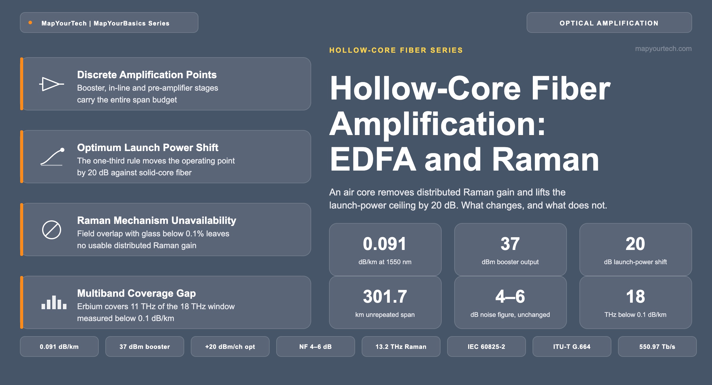
Hollow-Core Fiber Amplification: EDFA and Raman
Why an air core removes distributed Raman gain, raises the launch-power ceiling by three orders of magnitude, and hands the whole span budget to discrete amplifiers.
Launch power adds OSNR until nonlinear interference removes it faster.
1. Introduction
Hollow-core fiber (HCF) removes one of the two mechanisms a conventional line system uses to put power back into a span. In standard single-mode fiber (SSMF), span loss is recovered by a discrete erbium-doped fiber amplifier (EDFA) at a powered site, by distributed Raman gain generated inside the transmission fiber itself, or by both in a hybrid stage. Raman gain scales with the overlap between the optical field and the glass, and an anti-resonant hollow-core fiber holds more than 99.9% of the field in air, so the span produces no usable Raman gain (published system-level analysis). Every decibel of loss in an HCF span is therefore recovered by discrete amplifiers sitting at the two ends of it.
What the fiber returns in exchange is headroom. The nonlinear coefficient of an air core is about three orders of magnitude below silica (measured), so the Kerr penalty that holds SSMF per-channel launch power near 0 to +1 dBm (design practice) no longer binds. Reported experiments have launched 34.5 dBm and 37 dBm of total power into HCF spans, and 40 dBm into a single channel, with no observed nonlinear penalty (measured). That single change reshapes the amplifier specification: output power and gain rise, span lengths double, amplifier counts fall, and optical safety and component power handling move from background constraints to design drivers.
The sections below cover the definitions the arithmetic rests on, the architecture of an EDFA-only hollow-core line system, the trade-offs against SSMF amplifier practice, reported deployment and laboratory results, standards status, and the multiband amplifier work aimed at the wider low-loss window that HCF opens. Background on the fiber itself is available in the MapYourTech treatment of hollow-core fiber fundamentals and the road ahead.
2. Optical Amplification Definitions for Hollow-Core Spans
Optical amplification is the restoration of signal power inside a transmission path without converting the signal to electronics. A discrete amplifier holds its gain medium, a length of rare-earth-doped fiber, inside the equipment shelf; a distributed amplifier uses the transmission fiber as the gain medium. Span gain equals span loss when the line system runs at unity net gain.
2.1 Distinctions Between Adjacent Quantities
Discrete gain and distributed gain differ by where the amplifying medium sits: erbium-doped fiber inside a shelf for the first, the deployed span fiber itself for the second. Span loss is the attenuation between two consecutive amplification points, while the link budget is the sum of every span loss plus node insertion losses and margin allocations along the end-to-end path. On/off gain is the ratio of output power with the pump on to output power with the pump off; net gain is what remains after the amplifier's internal losses, and only net gain enters the span budget. Gain and noise figure are independent specifications of the same stage: gain sets how much power the amplifier returns, and noise figure sets how much amplified spontaneous emission (ASE) it adds while doing so. The MapYourTech reference on EDFA noise figure and ASE accumulation works through the second pair in detail.
Lspan (dB) = α (dB/km) × L (km) + Σ (splice and connector loss, dB)

OSNRspan (dB) = 58 + Pch (dBm) − Lspan (dB) − NF (dB)
Reference bandwidth is 12.5 GHz (0.1 nm at 1550 nm), which is what the constant 58 encodes.
Where:
- α = fiber attenuation coefficient, dB/km. Reported hollow-core values run from 0.05 to 0.25 dB/km depending on design and length (measured); deployed G.652.D sits at 0.18–0.20 dB/km (standard-specified range).
- L = span length between amplification points, km.
- Pch = per-channel optical power launched into the span, dBm.
- NF = amplifier noise figure, dB. Deployed C-band EDFAs run 4–6 dB (vendor-specified).
- 58 = the conversion constant for a 12.5 GHz reference bandwidth at 1550 nm, dB.
Practical Example — three-span hollow-core link OSNR
A reported 442.66 km hollow-core link is built from spans of 151.2 km, 150.5 km and 140.96 km, whose losses including all splices measured 37.4 dB, 36.5 dB and 41.9 dB (measured). Booster and in-line amplifiers each deliver 34.5 dBm total across 32 channels, giving 34.5 − 10·log10(32) = 19.5 dBm per channel (derived). At a 6 dB noise figure, the three per-span values come to 34.1 dB, 35.0 dB and 29.6 dB, and summing the three noise contributions in the power domain gives 27.4 dB at the receiver (derived). The reported receive OSNR across the 32 channels ran from 26.3 dB to 28.4 dB (measured), so the closed-form budget and the measurement agree to within the channel-to-channel spread. Note also what the arithmetic exposes: the shortest span carries the largest loss and contributes more than half the accumulated ASE.
Takeaway: Every decibel a hollow-core span loses is a decibel a discrete amplifier has to return. With no distributed stage available, span loss, per-channel launch power and noise figure are the only three variables in the optical signal-to-noise ratio (OSNR) budget, and the 58 form closes that budget on its own.
3. Amplification Architecture of a Hollow-Core Line System
Three amplifier positions carry a hollow-core link: a booster at the transmit terminal, an in-line amplifier at each intermediate site, and a pre-amplifier ahead of the receiver. That arrangement is the same one a solid-core line system uses, with one element deleted and one element changed. The deleted element is the distributed Raman stage, and the changed element is the output power the booster and in-line amplifiers are specified to deliver.
3.1 Discrete Gain Blocks and the Solid-Core Interior
The amplifier itself is unchanged silica technology. A coil of erbium-doped fiber, a 980 nm or 1480 nm pump laser diode, a wavelength-division coupler, isolators and a gain-flattening filter behave exactly as they do on a solid-core route, because the air core lies outside the shelf. Hollow-core fiber changes what sits between amplifiers, not what sits inside them, which is the reason existing amplifier product classes could be applied to reported hollow-core experiments without redesign of the gain block. Background on the gain mechanism is in the MapYourTech guide to EDFA technology and pump configurations.
One consequence of that split reaches the monitoring plane. Longitudinal power monitoring builds a power profile along a route from the nonlinear response of the fiber, and a hollow-core span with a nonlinear coefficient near 2.2 × 10⁻²³ m²/W produces almost none: in reported work the profile inside the hollow-core section was unavailable, and the short solid-core patch cords joining the span to the EDFA were what made power-profile estimation possible at all (measured). Gain flatness also changes character, because with no inter-channel Raman transfer the received tilt comes from amplifier gain shape and fiber loss variation alone. A 200.5 km hollow-core link showed about 1.5 dB of loss variation across the C-band (measured), against the several decibels of power tilt that inter-band Raman transfer imposes on a loaded C+L solid-core system.
3.2 Launch Power Ceiling and Span Length Selection
On standard single-mode fiber the locally optimum per-channel launch power sits near 0 to +1 dBm, where the rising amplified-spontaneous-emission term and the falling nonlinear term cross; the composition of the two is set out in the MapYourTech treatment of GSNR against OSNR, and Section 4 works the crossing through for both fiber types. In hollow-core fiber that crossing moves upward by 20 dB, so reported systems have used 34.5 dBm and 37 dBm boosters for loaded C-band operation and a 10 W stage for single-channel work (measured).
Span length follows from the same change. At below 0.1 dB/km, holding the conventional 80 km amplifier spacing cuts span loss to under half its usual value and leaves most of the amplifier's capability unused. Published analysis argues for roughly doubling span length instead: span loss returns to a familiar figure, amplifier count halves, and the amplifier requirement shifts toward high output power, high gain and low noise figure, which is a more achievable specification than a low-gain stage with very high output. Network-level modelling reports up to 39% lower power consumption per Tb/s when higher-output EDFAs are paired with hollow-core links, despite the higher electrical draw of each amplifier, and a 1,000 km C-band link modelled at its minimum energy-per-bit launch power showed 41.5% lower total power consumption for a 2.2% throughput penalty (both modelled).
3.3 Interconnection, Back-Reflection and Optical Safety
Every hollow-core span meets solid-core fiber at both ends, and that interface has an index step from about 1.45 to 1.00. Fresnel reflection at a normal-incidence interface is therefore near 3.4%, which is about 0.15 dB of transmission loss and about −14.7 dB of return loss (theoretical, from the index step). Angled splices and mode-field-matched designs remove most of it: fabricated links have measured splice losses of 0.1–0.15 dB per splice using power alignment, and return loss below −50 dB across the S, C and L bands (measured). The reflection figure is what makes this an amplifier problem rather than a loss problem. At a 34.5 dBm booster output, an unmitigated 3.4% reflection returns 19.8 dBm into the amplifier output stage (derived), which is above the input power any preamplifier or isolator is specified to absorb continuously.
Optical safety scales the same way. IEC 60825-2 requires a hazard-level assessment at every accessible location of an installed fiber system, and ITU-T G.664 defines the automatic power reduction (APR) and automatic laser shutdown (ALS) behaviour that keeps an open fiber below the assessed level. A booster running at 34.5 to 37 dBm sits roughly 12 to 14 dB above the output of a conventional DWDM booster, so the detection-and-shutdown interval that was adequate at 23 dBm has to shorten as output power rises, a point made explicitly in the amplifier-safety patent literature. The MapYourTech reference on automatic power reduction and eye safety covers the hazard levels and the restoration protocol.
Specify the booster, the interface and the safety function together. Output power, connector return loss and shutdown response time are one coupled requirement on a hollow-core line system, not three independent line items, because each of them is set by the same decision to run 12 dB or more above conventional launch power.
4. Amplifier Specification Differences Between Solid-Core and Hollow-Core Line Systems
An erbium-doped amplifier for a hollow-core span is the same device as one for a solid-core span, specified at a different operating point. Nothing inside the gain block changes: the erbium energy levels, the 980 nm and 1480 nm pump bands, the 3 dB quantum floor on noise figure and the 4 to 6 dB a deployed stage achieves are all properties of doped silica, and doped silica does not know what the span outside the shelf is made of. What changes is every number written on the outside of the box, and one mechanism disappears entirely.
Unchanged Amplifier Properties
- Gain medium: a coil of erbium-doped silica fiber inside the shelf.
- Pump bands: 980 nm and 1480 nm, with the same coupler and isolators.
- Noise figure: a 3 dB quantum floor, 4 to 6 dB in a deployed stage (vendor-specified).
- Gain mechanism: population inversion and stimulated emission, with ASE as the by-product.
- Conformance: ITU-T G.661 parameters and G.697 monitoring apply unaltered.
Relocated Operating Point
- Output power, up 12 to 14 dB.
- Per-channel launch, up about 20 dB.
- Span length and gain, roughly doubled.
- Distributed Raman, removed entirely.
- Safety and reflection limits, tightened.
| Parameter | Change | Solid-core line system | Hollow-core line system | What drives the difference |
|---|---|---|---|---|
| Booster total output power | Higher | +17 to +23 dBm (vendor-specified class) | 33 to 37 dBm in reported systems (measured) | The nonlinear ceiling that capped total power is removed |
| Per-channel launch power | Higher | 0 to +1 dBm at the local optimum | Around +20 dBm at the modelled optimum | Nonlinear interference power falls by 60 dB for a 1,000-fold lower nonlinear coefficient |
| Span length at 20 dB span loss | Higher | 80 to 100 km at 0.18–0.20 dB/km | 150 to 300 km at 0.09–0.13 dB/km | Attenuation roughly halved, so the same loss buys twice the distance |
| Amplifier gain | Higher | 16 to 22 dB per in-line stage | 20 to 40 dB per in-line stage | Longer spans and the choice to keep span loss constant rather than reduce it |
| Noise figure | No change | 4 to 6 dB (vendor-specified) | 4 to 6 dB, unchanged | The gain medium is identical; noise figure is an erbium property |
| Distributed Raman option | Removed | Available, 10 to 15 dB of on/off gain typical | Not available | Field overlap with glass below 0.1% in an air core |
| Effective span noise figure | Removed | Can fall below 0 dB with backward Raman | Bounded by the discrete pre-amplifier | No gain is delivered before the signal reaches its minimum power |
| Gain-flattening requirement | Relaxed | Amplifier gain shape plus inter-channel Raman tilt | Amplifier gain shape and fiber loss variation only | No power transfer between channels along the span |
| Automatic power reduction | Higher | Sized for roughly 20 dBm of accessible power | Sized for 12 to 14 dB more | Accessible power at an open connector scales with booster output |
| Output reflection tolerance | Higher | Connector and splice return loss within one glass type | Hollow-core to solid-core interface, 3.4% Fresnel unless angled | Refractive index step from about 1.45 to 1.00 at every span end |
One row of Table 1 reads differently from the rest. Noise figure is the only entry marked as unchanged, and it stays unchanged because it is a property of the erbium population inversion rather than of the span: a stage reaching 5 dB on a solid-core route reaches 5 dB on a hollow-core route at the same gain. Four rows move upward together and move for one shared reason, which is the subject of the next subsection. Two rows disappear with the distributed mechanism, and one relaxes because the transfer it used to correct for no longer happens.
4.1 Optimum Launch Power and the One-Third Rule
Two terms set the operating point, and they move in opposite directions with launch power. Accumulated ASE does not depend on channel power at all, so the OSNR term rises one decibel per decibel of added power. Nonlinear interference power grows as the cube of channel power under the Gaussian Noise model, so the nonlinear signal-to-noise term falls two decibels per decibel. One launch power maximises the combination.
OSNRASE(P) = A + P          SNRNLI(P) = C − 2P

Popt = (C − A − 3.01) / 3        GSNRmax = A + Popt − 1.76
All quantities in dB or dBm. The 3.01 term is the optimum condition that nonlinear interference power equals half the ASE power; the 1.76 term is the resulting penalty against the linear OSNR.
Where:
- P = per-channel launch power, dBm.
- A = accumulated ASE reference, dB, equal to 58 − span loss − noise figure − 10·log10(number of spans).
- C = nonlinear reference, dB, set by the fiber's nonlinear coefficient, span length, dispersion and channel plan.
- Popt = the launch power that maximises generalized signal-to-noise ratio (GSNR), dBm.
One consequence falls straight out of the algebra. Raising C by Δ decibels, which is what a lower nonlinear coefficient does, raises both Popt and GSNRmax by Δ/3 (derived). The factor of three is what converts a fiber property into an amplifier requirement, and it also explains why the reduction has to be counted correctly: nonlinear interference power scales with the square of the nonlinear coefficient, so a 1,000-fold reduction in that coefficient is a 60 dB reduction in interference power, not 30 dB. Sixty decibels divided by three is 20 dB, and that is the whole difference in operating point.
Practical Example — where each fiber type wants the booster set
Take ten spans of 20 dB loss with a 5.5 dB amplifier noise figure, which is 100 km of solid-core fiber at 0.20 dB/km or about 180 km of hollow-core fiber at 0.11 dB/km. The ASE reference A works out at 58 − 20 − 5.5 − 10 = 22.5 dB (derived). The solid-core case then optimises at 0 dBm per channel for 20.7 dB of GSNR, and the hollow-core case at +20 dBm per channel for 40.7 dB (modelled). With 32 channels the second figure is 35 dBm of total booster output, which sits inside the 33 to 37 dBm range reported systems have used, and the reported per-channel figure of 19.5 dBm falls 0.5 dB short of the modelled optimum — close enough that the amplifier's output limit and the fiber's optimum arrive at the same place.
4.2 Raman Amplification and Why the Mechanism Does Not Transfer
A distributed Raman amplifier has no gain block. The transmission fiber is the gain medium, which is the property that separates it from every other amplifier on the route and the property a hollow-core span cannot supply.
Raman Gain Generation in a Solid Silica Core
A pump near 1,450 nm is launched backward into the same fiber that carries the traffic. Pump photons scatter inelastically off the vibrating Si–O–Si bonds of the glass: each event gives up about 13.2 THz of energy to a lattice phonon and adds one photon to the signal at the Stokes frequency (measured, established fiber-optics literature). Because fused silica is amorphous, those vibrational frequencies merge into a continuum extending over roughly 40 THz rather than the discrete lines a crystal or a gas produces, which is why one pump amplifies a whole band and why several pump wavelengths can be combined into a flat wideband profile.
Three consequences follow from the medium being the span itself. Gain appears continuously along the fiber wherever pump power survives, typically within the first 20 to 25 km of the injection point in a backward-pumped design, so the signal is lifted before it reaches its minimum power and the effective span noise figure can fall below 0 dB. No equipment sits where the gain is produced, which is what makes the mechanism valuable on unrepeatered and festoon routes. And the gain is set by pump power rather than by a fixed inversion, with 10 to 15 dB of on/off gain typical for first-order pumping and multipath interference becoming appreciable somewhere around 15 to 20 dB (published characterisation).
Pump Behaviour in an Air Core
Launch that same pump, at the same wavelength and the same power, into an anti-resonant hollow-core fiber, and two things happen. It propagates to the far end with lower loss than it would in silica, and it converts almost none of its power into Stokes photons on the way. The bonds that supply the phonon are still present, but they are in the thin membranes surrounding the core, and the guided mode overlaps those membranes by under 0.1%.
The Raman gain a guided mode experiences scales with the fraction of the field in the glass and inversely with effective area, and both terms move the wrong way at once: the overlap is three orders of magnitude down, and the hollow-core mode field, roughly 70% of the air-core diameter (published analysis), is several times wider than the mode of a solid-core fiber. Recovering the 10 to 15 dB of on/off gain that under 1 W delivers on a solid-core span would take a pump larger by more than three orders of magnitude, which is kilowatt class (derived, order of magnitude). Hollow-core fiber will physically carry that: kilowatt-average-power transmission over kilometre-scale lengths and 2 kW over 2.45 km have both been demonstrated (measured). It is still not a line-system component. A kilowatt continuous-wave pump sharing a duct with live traffic fails every optical-safety assessment in Section 3.3, and whatever gain did appear would be generated in the membranes rather than in the core the signal occupies. The air core does not weaken Raman scattering as a physical process; it removes the material the process needs from the path the light takes.
Two further properties of that mechanism are worth naming, because both are sometimes assumed to survive the change.
The first is the gas in the core. Molecular gases do produce stimulated Raman scattering, and gas-filled hollow-core fibers are used as Raman converters for exactly that reason, but a gas gives discrete lines rather than the continuum an amorphous solid gives, and the shifts are an order of magnitude larger: hydrogen's vibrational shift of 4,155 cm−1 is about 124.6 THz, so amplifying a 1,550 nm signal would call for a pump near 943 nm rather than 1,450 nm (derived from the published shift). A telecom hollow-core fiber is not gas-filled by design in any case, and the residual atmospheric gas it does contain sits at a density that produces absorption lines rather than gain. The second is inter-channel Raman transfer, the unwanted form of the same mechanism, which tilts power from the blue edge of a loaded comb toward the red edge on a solid-core route. It disappears for the same reason the useful form does, and its disappearance is the one entry in Table 1 marked as relaxed.
Replacements for the Functions of the Distributed Stage
Distributed Raman did three jobs on a solid-core route, and hollow-core fiber replaces two of them by other means. Extending unrepeatered reach is replaced by launch power and lower attenuation: a 726.1 km single-span link closed on one high-power erbium stage at each end, where the comparable solid-core records needed high-order Raman pumps and four remote gain units (measured). Closing a high-loss span without building a new site is replaced by simply making the span longer at the same span loss, since attenuation is roughly halved. The third job has no replacement.
What the line system loses is the low-noise option rather than the decibels. Gain delivered inside the span holds the signal higher before it reaches its minimum, which is what allows an effective span noise figure below 0 dB and why hybrid stages exist on the longest solid-core spans; the mechanism behind that on/off gain has no hollow-core counterpart. A hollow-core budget that will not close therefore has to be closed with launch power, with a shorter span, or with a lower-noise discrete pre-amplifier, and never with distributed gain.
Takeaway: The amplifier hardware is the same on both fiber types and the noise figure is unchanged; what moves is the operating point, by 20 dB in launch power and in achievable GSNR for a 1,000-fold lower nonlinear coefficient. Raman is the one mechanism that does not transfer, because it needs the glass the hollow core was designed to avoid.
5. Advantages and Limitations of EDFA-Only Amplification
Removing the nonlinear ceiling produces the advantages; removing the second gain mechanism and admitting gas into the core produces the limitations. Table 2 sets out which mechanisms remain available.
| Mechanism | Gain medium | Solid-core span | Hollow-core span | Governing reason |
|---|---|---|---|---|
| Discrete EDFA, C and L bands | Erbium-doped silica in the shelf | Standard practice | Standard practice, at higher output power | The gain medium sits inside the equipment, so the span fiber type is immaterial |
| Distributed Raman | The deployed span fiber | Used on high-loss and unrepeatered spans | Not available | Raman gain scales with the overlap between the field and the glass, and the field is in air |
| Hybrid EDFA and Raman | Both | Used where the lowest effective noise figure is needed | Not available | The hybrid stage depends on the distributed half |
| Remote optically pumped amplifier | Erbium coil spliced into the span | Used on long unrepeatered links | Not reported in the hollow-core experiments reviewed here | The coil and its splices reintroduce solid-core fiber and its reflections into the span |
| Thulium-doped amplifier | Thulium-doped silica in the shelf | Emerging for S-band | Demonstrated in S+C+L transmission | The gain medium sits inside the equipment |
| Bismuth-doped amplifier | Bismuth-doped silica in the shelf | Emerging for O, E and S bands | Demonstrated in S+C+L transmission | The gain medium sits inside the equipment |
5.1 Advantages
Higher launch power converts directly into OSNR, one decibel for one decibel, with no nonlinear term to cancel it. That is what allows a hollow-core span to reach a distance a solid-core span reaches only with a Raman escalation: a reported 726.1 km unrepeatered 400G link closed a 73.3 dB loss budget using a single high-power EDFA at each end, where the comparable solid-core records used higher-order Raman pumps and four remote gain units on dedicated fibers (measured). Fewer amplifier sites follow from longer spans, and fewer sites means less power, fewer huts and fewer failure points. The absence of inter-channel Raman transfer removes power tilt across the comb, so wideband amplifier design no longer has to correct for the transfer that dominates C+L amplifier cascade planning on solid-core routes.
5.2 Limitations
The first limitation is the missing low-noise option set out in Section 4.2, which costs the escalation ladder used on unrepeatered links most of its rungs.
The second is gas line absorption. Residual carbon dioxide, carbon monoxide and water vapour trapped in the core produce narrow absorption lines rather than broadband loss. Reported gas-line absorption factors on C-band spans measured 0.03 to 0.07 dB/km at the worst absorbing frequency near 195.33 THz, and up to about 0.08 dB/km on an L-band line with a width of several gigahertz (measured). No amplifier corrects this. The lines are around 1 GHz wide and spaced near 40 GHz, so they fall inside a channel rather than across a band, and a gain-flattening filter or dynamic gain equalizer works at a resolution one to two orders of magnitude coarser. Mitigation moves to the transponder: transmitter power optimization raising the launch power of affected channels by about 6 dB delivered roughly 4 dB more receive OSNR and uniform pre-forward-error-correction bit error rate across 32 channels (measured), while spectral pre-equalisation and digital subcarrier placement have both been reported to recover several decibels of Q-factor penalty (measured and modelled).
The third is what the equipment has to survive: every passive component in the path, couplers, isolators, connectors and the multiplexer alike, now sees powers built for 34 dBm and above rather than 20 dBm. The fourth is per-amplifier electrical draw, which rises with output power. The network-level modelling above shows that trade closing in favour of the higher-power amplifier, but only when span lengths and amplifier counts are re-planned around it.
Takeaway: Hollow-core amplification trades a mechanism for a margin. The distributed stage disappears and takes the low-noise-figure option with it, while the launch-power ceiling rises by more than 12 dB and returns far more budget than the loss. What the trade does not cover is gas line absorption, which is invisible to every optical amplifier and has to be handled in the transponder.
6. Deployment Cases and Reported System Results
Reported hollow-core systems fall into three configurations, separated by how many amplifier sites the route carries: single-span unrepeatered links with amplifiers only at the terminals, multi-span links with in-line amplifiers, and short wideband links where the amplifier set rather than the distance is the subject of the experiment.
| Configuration | Distance (km) | Amplification | Reported result | Evidence class |
|---|---|---|---|---|
| Single span, loaded C-band | 301.7 | Booster to 37 dBm plus pre-amplifier | 25.6 Tb/s C-band capacity after 200.5 km | Measured |
| Single span, single channel | 726.1 | 10 W booster, 73.3 dB budget | 400G QPSK, real-time transceivers | Measured |
| Three spans, straight line | 442.7 | Booster and two in-line stages at 34.5 dBm | 32 × 800G with more than 1.5 dB Q-margin | Measured |
| Bidirectional, S+C+L | 10.9 | Thulium-doped stage plus C and L EDFAs | 550.97 Tb/s net rate, 393 × 2 channels | Measured |
| Wideband, S+C+L | 40.4 | Bismuth-doped fiber amplifiers | 137.6 Tb/s with constellation shaping | Measured |
| Hybrid hollow-core and solid-core span | 200.0 | Hollow-core first, solid-core tail with backward Raman | 25–50% less hollow-core fiber for equal capacity | Modelled |
The unrepeatered case is where the amplifier change shows most plainly. Solid-core reach records at 400G and 800G were set with high-order Raman pumps and multiple remote gain units on dedicated fibers; the hollow-core results were set with one high-power erbium stage at each end and nothing between them. Simplicity is the operational argument as much as the reach: fewer pump lasers, no remote gain unit qualification and no clean-fiber zone requirement around a Raman injection point.
The hybrid span puts the distributed stage back. Hollow-core fiber at the start of a span, where power is highest and nonlinearity would otherwise dominate, followed by solid-core fiber for the remainder, where the signal has already decayed, recovers backward Raman pumping at the receive end while keeping most of the nonlinear benefit. Modelling of 200 km spans reports 25% to 50% of the hollow-core length saved at equivalent capacity, with the benefit largest in metro systems where transceiver signal-to-noise ratio rather than fiber propagation sets the limit (modelled).
Laboratory span losses and cabled span losses are not the same number, and the multi-span link in Table 3 is the useful reference point. Its measured per-span figure of 37.4 dB over 151.2 km corresponds to about 0.25 dB/km once every splice in a 57-bobbin concatenation is counted (derived), against bare-fiber measurements between 0.11 and 0.24 dB/km for the same spools. A 2026 operator field trial on deployed hollow-core cable reported 1.2 Tb/s per wavelength over roughly 200 km without repeaters at system output power up to 33.5 dBm (trade-press report of an operator and vendor trial).
7. Standards and Vendor Support
Amplifier specification and measurement for hollow-core links sit under the same ITU-T recommendations that govern solid-core amplifiers. ITU-T G.661 defines the generic parameters and test methods for optical amplifier devices and subsystems, G.662 and G.663 cover generic characteristics and application-related aspects, and G.697 covers optical performance monitoring. G.665 covers Raman amplifiers and Raman-amplified subsystems, and has no hollow-core application for the reason Table 1 gives. Optical safety runs through IEC 60825-2, which requires hazard-level assessment at each accessible location of an installed system, and ITU-T G.664, which specifies the automatic power reduction and shutdown behaviour.
No published recommendation yet specifies an amplifier class against hollow-core spans, and the amplifiers used in reported experiments are erbium-doped stages built for high output power, in one case as part of a purpose-built bidirectional hollow-core line system. Fiber-side standardisation is further along in discussion than the amplifier side: ITU-T Study Group 15 work on hollow-core interoperability has produced three baseline criteria for interconnecting fiber from different manufacturers, namely equal mode field diameter, equal cladding diameter and equal operating window, with air-core diameter dominating mode field diameter at roughly 70% of core diameter and differing tube counts contributing around 0.045 dB of intrinsic loss (published analysis).
Public vendor positions agree on where the work sits. Microsoft, following its acquisition of Lumenisity, and the University of Southampton have published the fiber loss and unrepeatered transmission results; YOFC and China Telecom the fiber, field-trial and high-power unrepeatered results; ZTE the transponder-side mitigation of gas absorption; Nokia Bell Labs the hybrid span modelling. Nokia states that hollow-core fiber challenges both EDFA and Raman amplification because each relies on a silica gain medium, and that work on hybrid solid-core and hollow-core amplification, cladding pumping and wideband fiber amplifiers is under way (vendor statement). Adtran notes that reported experiments have used the highest available amplifier output power, launching up to 37 dBm into hollow-core fiber (vendor statement).
Takeaway: The standards a hollow-core amplifier is measured and made safe against already exist and need no change; what does not yet exist is a specified amplifier class for hollow-core spans, so output power, gain shape and shutdown response remain choices made in individual system design rather than points of conformance.
8. Multiband Amplification Beyond the C-Band
The fiber's low-loss window is now wider than the amplifier set that covers it. A double-nested anti-resonant nodeless fiber measured 0.091 dB/km at 1550 nm over a 15 km length and stayed below 0.1 dB/km from 1,481 to 1,625 nm, about 18 THz, while holding below 0.2 dB/km across roughly 66 THz from 700 nm to beyond 2,400 nm (measured). C- and L-band erbium amplifiers reach 1,530 to 1,625 nm, which is about 11 THz of that 18 THz window and a much smaller fraction of the wider one.
Two doped-fiber classes are already carrying hollow-core experiments. A record 550.97 Tb/s net rate over 10.9 km of nested anti-resonant nodeless fiber used a thulium-doped amplifier for the S-band alongside C- and L-band EDFAs across 393 channels in each direction on a 50 GHz grid (measured). An ultra-wideband S+C+L result of 137.6 Tb/s over 40.4 km of support-tube hollow-core fiber used bismuth-doped fiber amplifiers with constellation shaping (measured). Both classes cost something in efficiency: the power conversion efficiency of thulium- and bismuth-doped stages runs below that of an erbium stage, which changes the energy calculation that made wider bands attractive in the first place (published analysis).
Two other directions are in progress. Amplification inside the hollow-core fiber itself has been investigated numerically, using a partially doped cladding built from resonant and anti-resonant elements to balance confinement loss against the mode overlap that gain requires, with a thulium-doped design discussed as the worked case (published research). Separately, the gas absorption problem decides which slots in the wider window stay usable, and two development paths are open: purging and pressurising the core to keep the C and L bands clear, or shifting the operating window away from the strongest absorption lines. The band-plan reasoning in the MapYourTech treatment of band allocation strategy applies here with one term deleted, since no Raman coupling links the bands together.
Takeaway: Amplifier coverage, not fiber attenuation, now bounds how much of the hollow-core window a system can use. Thulium- and bismuth-doped stages extend that coverage at a conversion-efficiency cost, and gas absorption decides which slots inside the covered range are worth provisioning.
9. Summary of Changes and Invariants
Ten quantities move when a route is built on hollow-core fiber instead of standard single-mode fiber, and a shorter list stays exactly where it was. Both lists matter to a design review, because the second one is what allows existing amplifier products, existing budget arithmetic and existing conformance testing to carry over unaltered.
- Launch-power ceiling. Per-channel launch moves from 0 to +1 dBm at the solid-core optimum to about +20 dBm at the modelled hollow-core optimum, with 33 to 37 dBm of total booster output in reported systems (measured) against +17 to +23 dBm for a conventional booster (vendor-specified class).
- Number of gain mechanisms. Two become one. Distributed Raman, hybrid erbium-and-Raman stages and remote optically pumped amplification all depend on the span acting as a gain medium, and an air core supplies none of it.
- Span length and amplifier site count. The same 20 dB span loss buys 150 to 300 km instead of 80 to 100 km, so a route of fixed length carries roughly half the amplifier sites, half the huts and half the associated power and maintenance.
- Amplifier output and gain class. The specification moves from 16 to 22 dB of gain at moderate output to 20 to 40 dB at high output, which is a different product class even though the gain block inside is not.
- The operating-point arithmetic. Nonlinear interference power scales with the square of the nonlinear coefficient, so a 1,000-fold lower coefficient is 60 dB less interference, and optimum launch power and peak generalized signal-to-noise ratio (GSNR) each rise by one third of that, or 20 dB (derived, Section 4.1).
- Spectral tilt and gain flattening. Inter-channel Raman transfer disappears, so the several decibels of power tilt that dominate a loaded C+L solid-core system are absent and the gain-flattening filter answers only for amplifier gain shape and fiber loss variation, measured at about 1.5 dB across the C-band on a 200.5 km link (measured).
- Chromatic dispersion and receiver equalization. Dispersion falls from about 16.7 ps/(nm·km) to 2–3 ps/(nm·km) (measured), and the feed-forward equalizer shortens with it: about three symbol-spaced taps instead of nine at 10 km and 53 GBd, widening to five or six times fewer at metro distances (modelled).
- A new impairment class. Gas line absorption from residual carbon dioxide, carbon monoxide and water vapour adds narrow lines of 0.03 to 0.08 dB/km around 1 GHz wide (measured). No optical amplifier corrects them, so mitigation moves to the transponder through transmitter power optimization, pre-emphasis or subcarrier placement.
- Optical safety and interconnection. Accessible power at an open fiber rises 12 to 14 dB, shortening the automatic power reduction response the same design has to meet, and every span end gains a hollow-core to solid-core interface reflecting 3.4% unless the splice is angled (theoretical, from the 1.45 to 1.00 index step).
- Energy per delivered bit. Higher-output amplifiers draw more power each and fewer of them are needed, and network-level modelling reports the trade closing in favour of hollow-core by up to 39% in power per Tb/s, with 41.5% lower total consumption on a 1,000 km C-band link operated at its minimum energy-per-bit launch power (modelled).
Invariant Across Both Fiber Types
- The amplifier itself. Erbium-doped silica coil, 980 nm and 1480 nm pumps, couplers and isolators, all unaltered.
- Noise figure. A 3 dB quantum floor and 4 to 6 dB in a deployed stage, because inversion physics does not depend on the span.
- ASE accumulation and the budget arithmetic. Amplified spontaneous emission still adds span by span, and per-span OSNR is still 58 plus launch power minus span loss minus noise figure.
- Unity net gain. Amplifier gain still equals span loss, and the worst span still sets the budget.
- The transceiver contract. Coherent modulation formats, forward error correction overheads and required OSNR at the receiver are unchanged.
- Conformance. ITU-T G.661 amplifier parameters, G.697 monitoring, G.664 safety procedures and IEC 60825-2 hazard assessment apply as written.
Takeaway: The move to hollow-core fiber changes the operating point of the line system and one entry in its equipment list; it does not change the amplifier, the noise arithmetic or the standards that govern either. A design review that separates those two lists will find most of its existing practice still valid and its attention correctly focused on launch power, span planning, safety and gas absorption.
10. Conclusion
Amplification for hollow-core fiber is a narrower problem than amplification for solid-core fiber, and a harder one to specify. Only one mechanism remains, so the whole span budget rests on discrete stages whose output power, gain and noise figure are now the only levers a designer holds. Those levers turn out to be enough: launch powers 12 dB and more above conventional practice have closed 73 dB budgets on single spans and carried 32 channels of 800G across 442 km on three amplifier sites, results that solid-core systems reach only with distributed pumping and remote gain units. What remains open is coverage. The fiber offers a low-loss window several times wider than erbium can amplify, thulium and bismuth stages are extending into it at a cost in conversion efficiency, and the gas trapped inside the core still decides which slots inside that window a network can sell.
11. References
- ITU-T Recommendation G.661 — Definitions and test methods for the relevant generic parameters of optical amplifier devices and subsystems, ITU-T Study Group 15.
- ITU-T Recommendation G.663 — Application related aspects of optical amplifier devices and subsystems, ITU-T Study Group 15.
- ITU-T Recommendation G.664 — Optical safety procedures and requirements for optical transmission systems, ITU-T Study Group 15.
- IEC 60825-2 — Safety of laser products, Part 2: Safety of optical fibre communication systems, International Electrotechnical Commission.
- M. N. Petrovich et al., Broadband optical fibre with an attenuation lower than 0.1 decibel per kilometre, Nature Photonics.
- A. Ali et al., Unrepeated HCF Transmission over Spans up to 301.7 km, Optical Fiber Communication Conference, Optica Publishing Group.
- L. Feng et al., Real-time Unrepeatered Transmission of 400G/800G/1.2T over HCF only Using EDFA, Optical Fiber Communication Conference, Optica Publishing Group.
- X. Li et al., Beyond 550 Tb/s S+C+L-band Bidirectional Transmission over 10.9 km Anti-Resonant Hollow-Core Fiber, Optical Fiber Communication Conference, Optica Publishing Group.
- R. S. B. Ospina et al., Ultra-wideband S+C+L Transmission of 137.6 Tb/s over 40.4 km of Support Tube Hollow Core Fiber using Bismuth Doped Fiber Amplifiers and Constellation Shaping, European Conference on Optical Communication.
- W. Belardi, P. J. Sazio and L. Bigot, Hollow core fibers for optical amplification, Optics Letters, Optica Publishing Group.
Related Articles on MapYourTech