
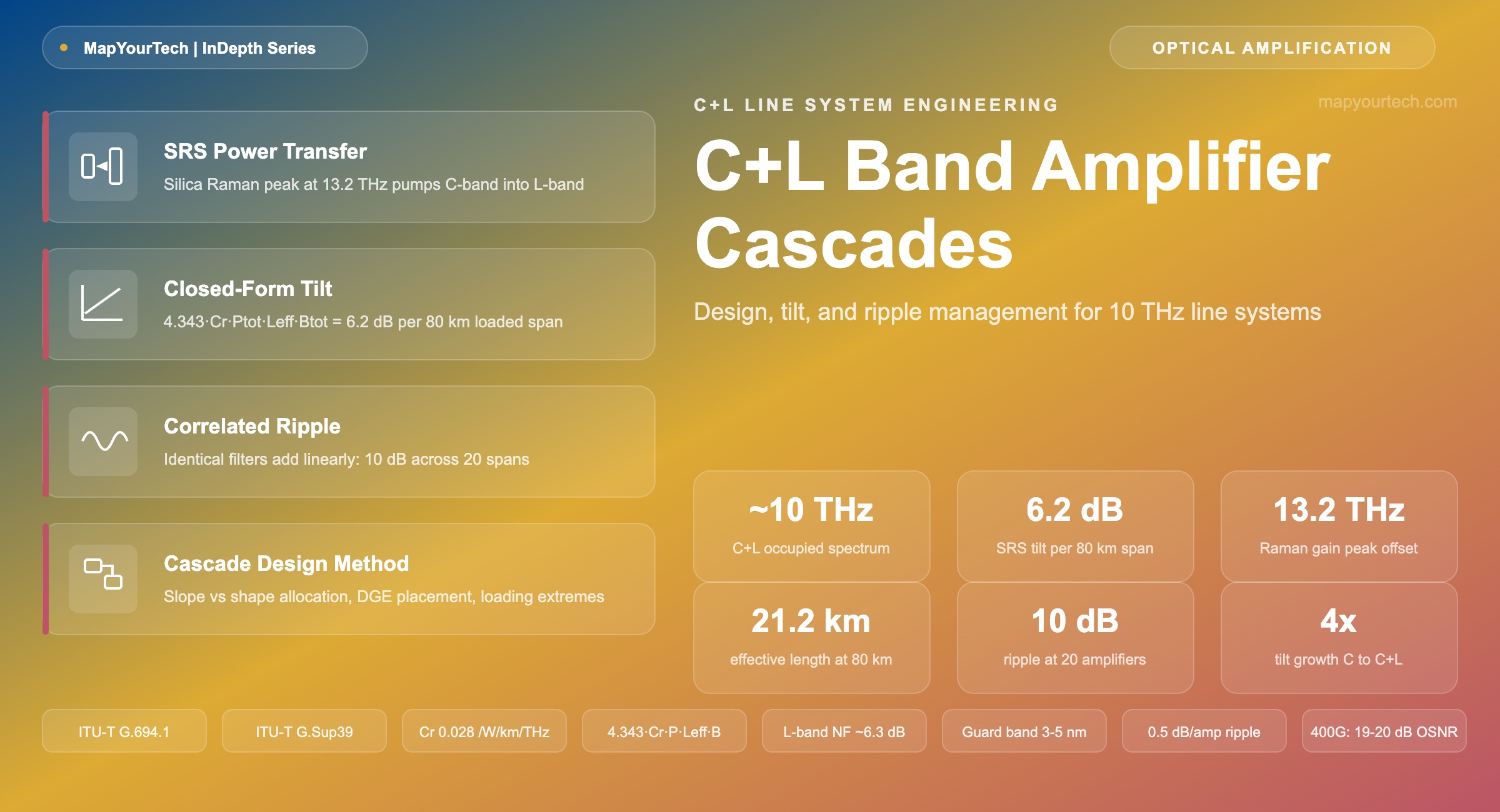
C+L Band Amplifier Cascades: Design, Tilt, and Ripple Management
Opening the L-band doubles the spectrum on fibre you already own, and hands the line-system designer two problems that C-band-only engineering never had to solve: a multi-decibel power tilt that the signals themselves create, and a gain ripple that stops averaging out once the cascade gets long.
1. Introduction
A fully loaded C+L span moves roughly 6 to 8 dB of optical power from the short-wavelength end of the spectrum to the long-wavelength end, and it does so without any component being at fault. The transfer is the signal population amplifying itself through the silica lattice: C-band channels act as Raman pumps for L-band channels sitting about 10 THz below them in frequency, right on the rising edge of the fused-silica Raman gain curve whose peak sits near a 13.2 THz Stokes shift. Every span does it again. By span three, an uncorrected cascade has a 20 dB spread across the band and the C-band edge channels are in the noise.
That single mechanism is why C+L amplifier cascade design is a different discipline from C-band cascade design rather than a wider version of it. In a C-band-only system the same physics is present, but a 4.8 THz occupied bandwidth and a few hundred milliwatts of aggregate power put the tilt in the range that a fixed per-amplifier tilt setpoint absorbs without much thought. Double the bandwidth and the tilt roughly doubles with it, because the tilt scales with the product of total power and total bandwidth. The correction stops being a trim and becomes a first-order design variable that the amplifier hardware, the control plane, and the channel plan all have to serve.
Tilt has a companion problem that gets less attention and causes more late-stage surprises. Gain ripple is the wavelength-dependent structure that an amplifier's gain leaves behind after the gain-flattening filter has done its work: the residual mismatch between the erbium emission spectrum, the filter's inverse transfer function, and the operating inversion the amplifier actually runs at. On one amplifier it is a fraction of a decibel and nobody notices. Across twenty identical amplifiers in a cascade it is not a fraction of a decibel, because identical amplifiers have identical ripple and identical errors add linearly rather than averaging out. Tilt is a slope you can correct with one number per amplifier. Ripple is a shape, and correcting a shape needs either a filter matched to it or a device with enough spectral resolution to draw the inverse.
This article works through both from the physics up. It derives the tilt expression that C+L design actually runs on, checks it against two independently published operating points, and shows why the number lands where field measurements put it. It then goes through amplifier architectures at the component level, the sources and accumulation behaviour of ripple, the modelling framework that connects launch power to received generalised signal-to-noise ratio, and the control-loop and loading questions that decide whether a design that looks right in the planning tool also behaves during a protection switch. The framing throughout is a working line system on installed fibre, not a laboratory record attempt, though the record results are worth knowing because they mark where the technology is heading.
The reader this is written for already knows what an erbium-doped fibre amplifier (EDFA) is and has probably specified one. What is harder to find in one place is the connective tissue: why the tilt formula has the shape it has, why a Raman stage changes the ripple problem and not just the noise problem, why a design that is stable at full fill can oscillate at 30 percent fill, and what the trade is between a static gain-flattening filter, a dynamic gain equaliser, and per-channel shaping at the wavelength-selective switch. Those connections are the article.
2. Capacity Motivation and Physical Penalties
The commercial motivation for C+L is spectral. ITU-T G.Sup39 places the conventional C-band at 1530 to 1565 nm and the long-wavelength L-band at 1565 to 1625 nm (standard-specified), corresponding to approximately 4.4 THz and 7.1 THz respectively. No commercial system uses the full L-band definition: the erbium gain coefficient falls below usable levels well before 1625 nm, and practical L-band EDFAs cover roughly 1570 to 1610 nm. A typical commercial C+L line system therefore operates with close to 4.8 THz per band and about 10 THz of occupied spectrum in total, on fibre that is already installed, spliced, and permitted.
The alternative capacity mechanisms carry higher entry constraints. Lighting a second fibre pair requires acquiring or leasing one, which on a long-haul route is a capital and lead-time constraint rather than an engineering one. Space-division multiplexing requires new cable plant rather than new terminal equipment. Higher-order modulation increases capacity only where optical signal-to-noise ratio (OSNR) margin already exists, and on the long spans where additional capacity is most needed it usually does not. Spectrum extension is the only mechanism that scales capacity approximately linearly with the cost of one additional amplifier band while operating on the installed fibre. The trade-space across all candidate transmission bands is covered in the MapYourTech guide to future optical bands for fibre communication.
2.1 Penalty mechanisms of the extended spectrum
Four penalty mechanisms apply. The first dominates the line-system design; the remaining three are smaller individually but enter every link budget.
Inter-channel stimulated Raman scattering. The dominant mechanism. Doubling the occupied bandwidth approximately doubles the power tilt, and doubling the channel count doubles it again through the total-power term. A C-band-only system running 96 channels at +1 dBm carries about 0.12 W of aggregate power over 4.8 THz; the same system extended to C+L carries about 0.24 W over 9.6 THz. Because tilt scales with the product of total power and total bandwidth, it increases by approximately a factor of four, not two.
Higher L-band attenuation. Silica loss has its minimum inside the C-band and rises monotonically through the L-band. On modern G.652.D production fibre the difference between the 1550 nm minimum and the 1610 nm end of the practical L-band is on the order of 0.02 dB/km (typical measured value; exact figures are fibre- and lot-dependent). Over an 80 km span this adds approximately 1.6 dB of span loss at the L-band edge, which combines directly with the noise-figure penalty described next.
Higher L-band amplifier noise figure. L-band EDFAs run a longer erbium fibre at lower average inversion to reach gain at 1580 to 1600 nm, and lower inversion increases the spontaneous-emission factor. Published amplifier specifications commonly place L-band noise figure approximately 0.5 to 1 dB above the C-band equivalent for the same gain (vendor-specified range, platform-dependent). The MapYourTech EDFA technology guide covers the inversion-to-noise-figure relationship in detail.
Guard-band and coupler loss. A banded architecture requires a C/L splitter at the input of every amplifier site and a combiner at the output. Each pair adds insertion loss to both bands and consumes a guard band between the bands — typically 3 to 5 nm — that no channel can occupy. Both terms recur at every amplifier site and enter the link budget directly: the guard band as unusable spectrum, the coupler insertion loss as an OSNR reduction.
Two mechanisms partially offset these penalties. Chromatic dispersion is higher at longer wavelengths, and higher dispersion decorrelates the phase interactions that generate nonlinear interference, so the L-band tolerates the same launch power with a lower nonlinear penalty. Inter-channel stimulated Raman scattering also transfers power into the L-band, so a system launched with equal per-channel power arrives with the L-band channels at higher power. The L-band therefore has a different launch-power optimum and a different impairment profile from the C-band, not uniformly worse performance.
Takeaway: C+L approximately doubles the usable spectrum for the cost of one additional amplifier band per site and one C/L coupler pair per site, and introduces an SRS tilt that scales with the product of total power and total bandwidth — an increase of approximately four times, not two, when a loaded C-band system is extended into the L-band.
3. Band Boundaries, Fibre, and the Real Spectrum
ITU-T G.Sup39 fixes the single-mode spectral band descriptors, and it is worth quoting the boundaries precisely because commercial usage drifts from them constantly: O-band 1260 to 1360 nm, E-band 1360 to 1460 nm, S-band 1460 to 1530 nm, C-band 1530 to 1565 nm, L-band 1565 to 1625 nm, U-band 1625 to 1675 nm (standard-specified). The Supplement is explicit that these definitions exist to facilitate discussion and are not themselves specifications — the operating wavelength ranges that matter are in the individual system Recommendations. It also notes that EDFAs with flatter and wider gain have become available and that no limitation of EDFAs to the C-band is implied. That caveat is doing real work: several commercial platforms run an extended C-band to 1568 nm to reach 110 channels on a 50 GHz grid, which sits outside the G.Sup39 C-band boundary and inside the G.Sup39 L-band.
The channel plan itself comes from ITU-T G.694.1, which fixes the DWDM frequency grid and, in its flexible-grid form, the 6.25 GHz slot granularity and 12.5 GHz minimum slot width that modern C+L systems use to fit mixed 400G and 800G carriers. Published S+C+L modelling work places the nominal band edges at 191.275 to 196.075 THz for the C-band and 185.975 to 190.775 THz for the L-band on the G.694.1 grid — 4.8 THz each with a 0.5 THz gap between them, which is the guard band the C/L coupler needs.
Read the Full Analysis with Premium
The remaining 89% of this article — the design numbers, trade-offs and field guidance — is part of MapYourTech Premium, along with the full premium library, courses and professional tools.
You May Also Like

-
Premium
-
August 18, 2026

-
Free
-
August 18, 2026

-
Free
-
August 18, 2026