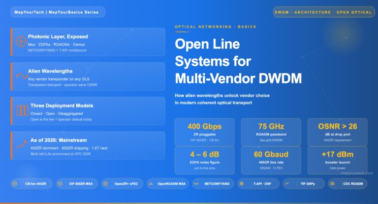
Open Line Systems: Multi-Vendor Coherent Wavelengths Skip to main content MapYourTech · MapYourBasics Series Open Line Systems: Multi-Vendor Coherent Wavelengths...
Stimulated Brillouin Scattering: Threshold Power, Line Narrowing Effect, and Launch Power Mitigation Fiber Nonlinearity Series Stimulated Brillouin Scattering: Threshold Power,...
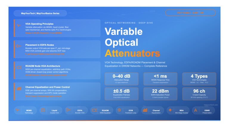
Variable Optical Attenuators (VOAs) in DWDM Systems | MapYourTech Optical Networking Variable Optical Attenuators (VOAs) in DWDM Systems A comprehensive...
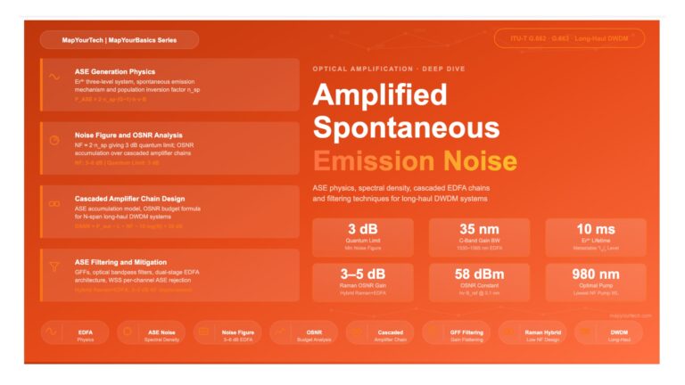
Amplified Spontaneous Emission (ASE) Noise in EDFA Systems Amplified Spontaneous Emission (ASE) Noise in EDFA Systems A comprehensive engineering reference...
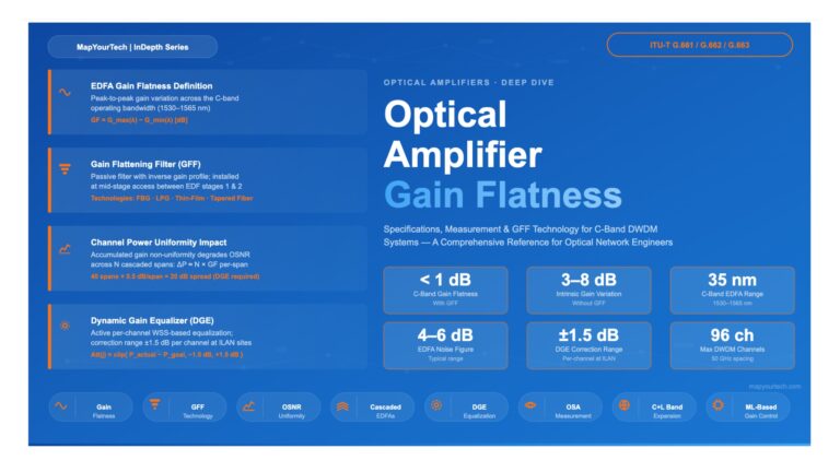
Optical Amplifier Gain Flatness: Specifications and Measurement Optical Amplifier Gain Flatness:Specifications and Measurement A comprehensive reference for optical networking engineers...
Get new articles, courses & exclusive offers first
Follow MapYourTech on LinkedIn for exclusive updates — new technical articles, course launches, member discounts, tool releases, and industry insights straight to your feed.