
HomePosts tagged “amplifier”
amplifier
Showing 1 - 5 of 5 results
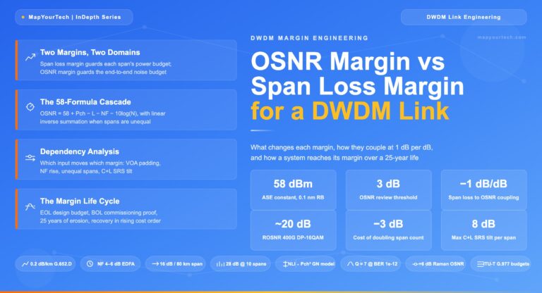
OSNR Margin vs Span Loss Margin in DWDM Links MAPYOURTECH | INDEPTH SERIES OSNR Margin vs Span Loss Margin in...
-
Free
-
June 11, 2026
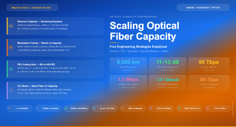
Scaling Optical Fiber Capacity: Five Engineering Strategies Explained Optical Capacity Engineering Series — Comprehensive Deep Dive Scaling Optical Fiber Capacity:Five...
-
Free
-
April 5, 2026
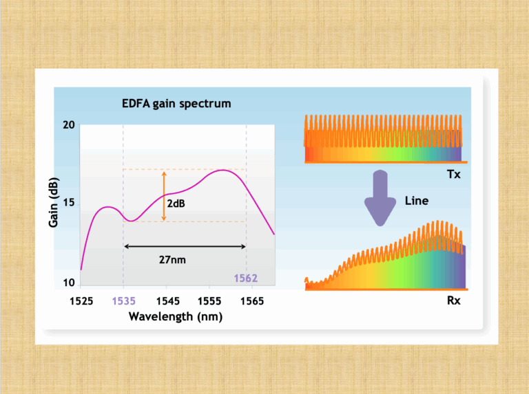
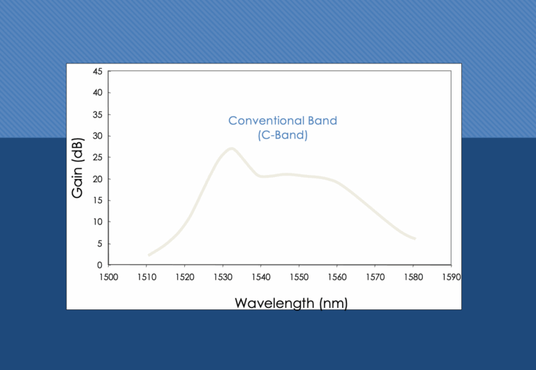
EDFA stands for Erbium-doped fiber amplifier, and it is a type of optical amplifier used in optical communication systems What...
-
Free
-
March 26, 2025
Compared with requirements for EDFAs for terrestrial applications and for Submarine applications, there are major important differences making the two...
-
Free
-
March 26, 2025
Background Information The Raman amplifier is typically much more costly and has less gain than an Erbium Doped Fiber Amplifier (EDFA)...
-
Free
-
March 26, 2025
Explore Articles
- Analysis
- Automation
- Careers and Learning Paths
- Coherent Optics
- Data Center Interconnect
- Free
- Fundamentals
- Management
- Network Architecture
- Planning & Design
- Premium
- Professional Development
- Security
- Standards
- Submarine and Long-Haul
- Technical
- Testing
- Tools and Simulators
- Trends & News
- Troubleshooting and Operations
- Vendor and Product Landscape
Filter Articles
ResetExplore Courses
Tags
400ZR
automation
behavioral
behavioral interview
ber
candidate
career
COHERENT
coherent optical transmission
coherent optics
data center interconnect
Data transmission
DWDM
edfa
EDFA noise figure
Fiber optics
Fiber optic technology
Forward Error Correction
hiring
Interview
Latency
modulation
network automation
noise figure
optical
Optical communication
Optical fiber
Optical network
optical network automation
optical networking
Optical signal-to-noise ratio
OSNR
OSNR calculation
OTN
preparation
Probabilistic Constellation Shaping
Q-factor
recruiter
ROADM
Signal quality
Slider
spectral efficiency
STAR
submarine
Ticker