Background Information
- The Raman amplifier is typically much more costly and has less gain than an Erbium Doped Fiber Amplifier (EDFA) amplifier. Therefore it is used only for speciality applications.
- The main advantage that this amplifier has over the EDFA is that it generates very less noise and hence does not degrade span Optical to Signal Noise Ratio (OSNR) as much as the EDFA.
- Its typical application is in EDFA spans where additional gain is required but the OSNR limit has been reached.
- Adding a Raman amplifier might not significantly affect OSNR, but can provide up to a 20dB signal gain.
- Another key attribute is the potential to amplify any fiber band, not just the C band as is the case for the EDFA. This allows for Raman amplifiers to boost signals in O, E, and S bands (for Coarse Wavelength Division Multiplexing (CWDM) amplification application).
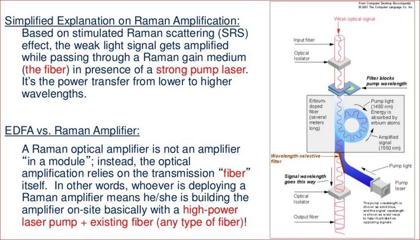
- The amplifier works on the principle of Stimulated Raman Scattering (SRS), which is a nonlinear effect.
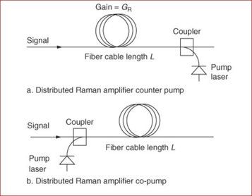
- It consists of a high-power pump laser and fiber coupler (optical circulator).
- The amplification medium is the span fiber in a Distributed Type Raman Amplifier (DRA).
- Distributed Feedback (DFB) laser is a narrow spectral bandwidth which is used as a safety mechanism for Raman Card. DFB sends pulse to check any back reflection that exists in the length of fiber. If no High Back Reflection (HBR) is found, Raman starts to transmit.
- Generally HBR is checked in initial few kilometers of fibers to first 20 Km. If HBR is detected, Raman will not work. Some fiber activity is needed after you find the problem area via OTDR.
Common Types of Raman Amplifiers
- The lumped or discrete type Raman amplifier internally contains a sufficiently long spool of fiber where the signal amplification occurs.
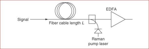
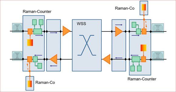
- The DRA pump laser is connected to the fiber span in either a counter pump (reverse pump) or a co-pump (forward pump) or configuration.
- The counter pump configuration is typically preferred since it does not result in excessively high signal powers at the start of the fiber span, which can result in nonlinear distortions as shown in the image.
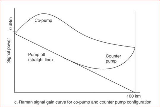
The advantage of the co-pump configurations is that it produces less noise.
Principle
As the pump laser photons propagate in the fiber, they collide and are absorbed by fiber molecules or atoms. This excites the molecules or atoms to higher energy levels. The higher energy levels are not stable states so they quickly decay to lower intermediate energy levels that release energy as photons in any direction at lower frequencies. This is known as spontaneous Raman scattering or Stokes scattering and contributes to noise in the fiber.
Since the molecules decay to an intermediate energy vibration level, the change in energy is less than the initial received energy at the time of molecule excitation. This change in energy from excited level to intermediate level determines the photon frequency since Δ f = Δ E / h. This is referred to as the Stokes frequency shift and determines the Raman gain versus frequency curve shape and location. The energy that remains from the intermediate level to ground level is dissipated as molecular vibrations (phonons) in the fiber. Since there exists a wide range of higher energy levels, the gain curve has a broad spectral width of approximately 30 THz.
At the time of the stimulated Raman scattering, signal photons co-propagate frequency gains curve spectrum, and acquires energy from the Stokes wave, that results in signal amplification.
Theory of Raman Gain
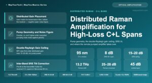
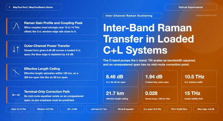
The Raman gain curve’s FWHM width is about 6THz (48 nm) with a peak at about 13.2THz under the pump frequency. This is the useful signal amplification spectrum. Therefore, in order to amplify a signal in the 1550 nm range the pump laser frequency is required to be 13.2THz below the signal frequency at about 1452 nm.
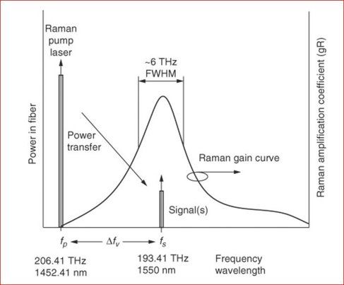
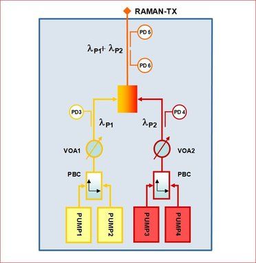
Multiple pump lasers with side-by-side gain curves are used to widen the total Raman gain curve.
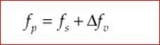
Where fp = pump frequency, THz fs = signal frequency, THz Δ f v = Raman Stokes frequency shift, THz.
Raman gain is the net signal gain distributed over the fiber’s effective length. It is a function of pump laser power, fiber effective length, and fiber area.
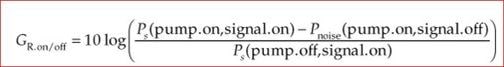
For fibers with a small effective area, such as in dispersion compensation fiber, Raman gain is higher. Gain is also dependent on the signal separation from the laser pump wavelength, Raman signal gain is also specified and field measured as on/off gain. This is defined as the ratio of the output signal power with the pump laser on and off. In most cases the Raman ASE noise has little effect on the measured signal value with the pump laser on. However, if there is considerable noise, which can be experienced when the measurement spectral width is large, then the noise power measured with the signal off is subtracted from the pump on signal power in order to obtain an accurate on/off gain value. The Raman on/off gain is often referred to as the Raman gain.
Noise Sources
Noise created in a DRA span consists:
- Amplified Spontaneous Emissions (ASE)
- Double Rayleigh Scattering (DRS)
- Pump Laser Noise
ASE noise is due to photon generation by spontaneous Raman scattering.
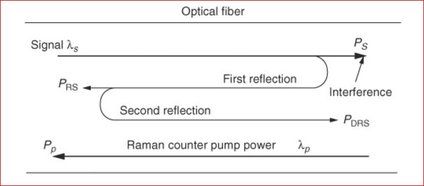
DRS noise occurs when twice reflected signal power due to Rayleigh scattering is amplified and interferes with the original signal as crosstalk noise.
The strongest reflections occur from connectors and bad splices.
Typically DRS noise is less than ASE noise, but for multiple Raman spans it can add up. In order to reduce this interference, Ultra Polish Connectors (UPC) or Angle Polish Connectors (APC) can be used. Optical isolators can be installed after the laser diodes in orer to reduce reflections into the laser. Also, span OTDR traces can help locate high-reflective events for repair.
Counter pump DRA configuration results in better OSNR performance for signal gains of 15 dB and greater. Pump laser noise is less of a concern because it usually is quite low with RIN of better than 160 dB/Hz.
Nonlinear Kerr effects can also contribute to noise due to the high laser pump power. For fibers with low DRS noise, the Raman noise figure due to ASE is much better than the EDFA noise figure. Typically, the Raman noise figure is –2 to 0 dB, which is about 6 dB better than the EDFA noise figure.
Raman amplifier noise factor is defined as the OSNR at the input of the amplifier to the OSNR at the output of the amplifier.
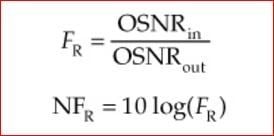
Noise figure is the dB version of noise factor.
The DRA noise and signal gain is distributed over the span fiber’s effective length.
Counter pump distributed Raman amplifiers are often combined with EDFA pre-amps to extend span distances. This hybrid configuration can provide 6dB improvement in the OSNR, which can significantly extend span lengths or increase span loss budget. Counter pump DRA can also help reduce nonlinear effects and allows for channel launch power reduction.
Functional Block Diagram for CoPropagating and Counter Propagating Raman Amplifier
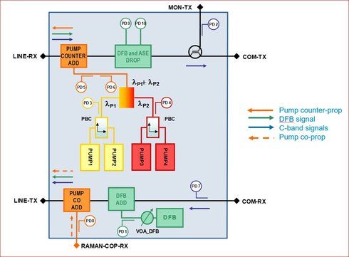
Field Deployment architecture of EDFA and RAMAN Amplifiers:
Interesting to know:
Related Information
- Planning Fiber Optic Networks by Bob Chomycz
- https://www.cisco.com/c/en/us/products/collateral/optical-networking/ons-15454-series-multiservice-provisioning-platforms/data_sheet_c78-658538.html
- Technical Support & Documentation – Cisco Systems