Tag

Raman Amplifier

Browsing

In the context of Raman amplifiers, the noise figure is typically not negative. However, when comparing Raman amplifiers to other amplifiers, such as erbium-doped fiber amplifiers (EDFAs), the effective noise figure may appear to be negative due to the distributed nature of the Raman gain.

The noise figure (NF) is a parameter that describes the degradation of the signal-to-noise ratio (SNR) as the signal passes through a system or device. A higher noise figure indicates a greater degradation of the SNR, while a lower noise figure indicates better performance.

In Raman amplification, the gain is distributed along the transmission fiber, as opposed to being localized at specific points, like in an EDFA. This distributed gain reduces the peak power of the optical signals and the accumulation of noise along the transmission path. As a result, the noise performance of a Raman amplifier can be better than that of an EDFA.

When comparing Raman amplifiers with EDFAs, it is sometimes possible to achieve an effective noise figure that is lower than that of the EDFA. In this case, the difference in noise figure between the Raman amplifier and the EDFA may be considered “negative.” However, this does not mean that the Raman amplifier itself has a negative noise figure; rather, it indicates that the Raman amplifier provides better noise performance compared to the EDFA.

In conclusion, a Raman amplifier itself does not have a negative noise figure. However, when comparing its noise performance to other amplifiers, such as EDFAs, the difference in noise figure may appear to be negative due to the superior noise performance of the Raman amplifier.

To better illustrate the concept of an “effective negative noise figure” in the context of Raman amplifiers, let’s consider an example comparing a Raman amplifier with an EDFA.

Suppose we have a fiber-optic communication system with the following parameters:

  1. Signal wavelength: 1550 nm
  2. Raman pump wavelength: 1450 nm
  3. Transmission fiber length: 100 km
  4. Total signal attenuation: 20 dB
  5. EDFA noise figure: 4 dB

Now, we introduce a Raman amplifier into the system to provide distributed gain along the transmission fiber. Due to the distributed nature of the Raman gain, the accumulation of noise is reduced, and the noise performance is improved.

Let’s assume that the Raman amplifier has an effective noise figure of 1 dB. When comparing the noise performance of the Raman amplifier with the EDFA, we can calculate the difference in noise figure:

Difference in noise figure = Raman amplifier noise figure – EDFA noise figure = 1 dB – 4 dB = -3 dB

In this example, the difference in noise figure is -3 dB, which may be interpreted as an “effective negative noise figure.” It is important to note that the Raman amplifier itself does not have a negative noise figure. The negative value simply represents a superior noise performance when compared to the EDFA.

This example demonstrates that the effective noise figure of a Raman amplifier can be lower than that of an EDFA, resulting in better noise performance and an improved signal-to-noise ratio for the overall system.

The example highlights the advantages of using Raman amplifiers in optical communication systems, especially when it comes to noise performance. In addition to the improved noise performance, there are several other benefits associated with Raman amplifiers:

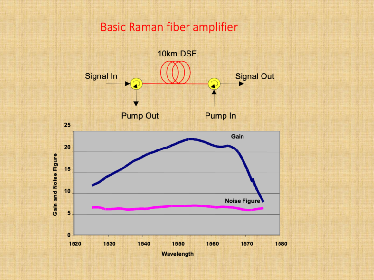
  1. Broad gain bandwidth: Raman amplifiers can provide gain over a wide range of wavelengths, typically up to 100 nm or more, depending on the pump laser configuration and fiber properties. This makes Raman amplifiers well-suited for dense wavelength division multiplexing (DWDM) systems.
  2. Distributed gain: As previously mentioned, Raman amplifiers provide distributed gain along the transmission fiber. This feature helps to mitigate nonlinear effects, such as self-phase modulation and cross-phase modulation, which can degrade the signal quality and limit the transmission distance.
  3. Compatibility with other optical amplifiers: Raman amplifiers can be used in combination with other optical amplifiers, such as EDFAs, to optimize system performance by leveraging the advantages of each amplifier type.
  4. Flexibility: The performance of Raman amplifiers can be tuned by adjusting the pump laser power, wavelength, and configuration (e.g., co-propagating or counter-propagating). This flexibility allows for the optimization of system performance based on specific network requirements.

As optical communication systems continue to evolve, Raman amplifiers will likely play a significant role in addressing the challenges associated with increasing data rates, transmission distances, and network capacity. Ongoing research and development efforts aim to further improve the performance of Raman amplifiers, reduce costs, and integrate them with emerging technologies, such as software-defined networking (SDN), to enable more intelligent and adaptive optical networks.

  1. What is a Raman amplifier?

A: A Raman amplifier is a type of optical amplifier that utilizes stimulated Raman scattering (SRS) to amplify optical signals in fiber-optic communication systems.

  1. How does a Raman amplifier work?

A: Raman amplification occurs when a high-power pump laser interacts with the optical signal in the transmission fiber, causing energy transfer from the pump wavelength to the signal wavelength through stimulated Raman scattering, thus amplifying the signal.

  1. What is the difference between a Raman amplifier and an erbium-doped fiber amplifier (EDFA)?

A: A Raman amplifier uses stimulated Raman scattering in the transmission fiber for amplification, while an EDFA uses erbium-doped fiber as the gain medium. Raman amplifiers can provide gain over a broader wavelength range and have lower noise compared to EDFAs.

  1. What are the advantages of Raman amplifiers?

A: Advantages of Raman amplifiers include broader gain bandwidth, lower noise, and better performance in combating nonlinear effects compared to other optical amplifiers, such as EDFAs.

  1. What is the typical gain bandwidth of a Raman amplifier?

A: The typical gain bandwidth of a Raman amplifier can be up to 100 nm or more, depending on the pump laser configuration and fiber properties.

  1. What are the key components of a Raman amplifier?

A: Key components of a Raman amplifier include high-power pump lasers, wavelength division multiplexers (WDMs) or couplers, and the transmission fiber itself, which serves as the gain medium.

  1. How do Raman amplifiers reduce nonlinear effects in optical networks?

A: Raman amplifiers can be configured to provide distributed gain along the transmission fiber, reducing the peak power of the optical signals and thus mitigating nonlinear effects such as self-phase modulation and cross-phase modulation.

  1. What are the different types of Raman amplifiers?

A: Raman amplifiers can be classified as discrete Raman amplifiers (DRAs) and distributed Raman amplifiers (DRAs). DRAs use a separate section of fiber as the gain medium, while DRAs provide gain directly within the transmission fiber.

  1. How is a Raman amplifier pump laser configured?

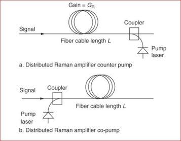
A: Raman amplifier pump lasers can be configured in various ways, such as co-propagating (pump and signal travel in the same direction) or counter-propagating (pump and signal travel in opposite directions) to optimize performance.

  1. What are the safety concerns related to Raman amplifiers?

A: The high-power pump lasers used in Raman amplifiers can pose safety risks, including damage to optical components and potential harm to technicians if proper safety precautions are not followed.

  1. Can Raman amplifiers be used in combination with other optical amplifiers?

A: Yes, Raman amplifiers can be used in combination with other optical amplifiers, such as EDFAs, to optimize system performance by leveraging the advantages of each amplifier type.

  1. How does the choice of fiber type impact Raman amplification?

A: The choice of fiber type can impact Raman amplification efficiency, as different fiber types exhibit varying Raman gain coefficients and effective area, which affect the gain and noise performance.

  1. What is the Raman gain coefficient?

A: The Raman gain coefficient is a measure of the efficiency of the Raman scattering process in a specific fiber. A higher Raman gain coefficient indicates more efficient energy transfer from the pump laser to the optical signal.

  1. What factors impact the performance of a Raman amplifier?

A: Factors impacting Raman amplifier performance include pump laser power and wavelength, fiber type and length, signal wavelength, and the presence of other nonlinear effects.

  1. How does temperature affect Raman amplifier performance?

A: Temperature can affect Raman amplifier performance by influencing the Raman gain coefficient and the efficiency of the stimulated Raman scattering process. Proper temperature management is essential for optimal Raman amplifier performance.

  1. What is the role of a Raman pump combiner?

A: A Raman pump combiner is a device used to combine the output of multiple high-power pump lasers, providing a single high-power pump source to optimize Raman amplifier performance.

  1. How does polarization mode dispersion (PMD) impact Raman amplifiers?

A: PMD can affect the performance of Raman amplifiers by causing variations in the gain and noise characteristics for different polarization states, potentially leading to signal degradation.

  1. How do Raman amplifiers impact optical signal-to-noise ratio (OSNR)?

A: Raman amplifiers can improve the OSNR by providing distributed gain along the transmission fiber and reducing the peak power of the optical signals, which helps to mitigate nonlinear effects and improve signal quality.

  1. What are the challenges in implementing Raman amplifiers?

A: Challenges in implementing Raman amplifiers include the need for high-power pump lasers, proper safety precautions, temperature management, and potential interactions with other nonlinear effects in the fiber-optic system.

  1. What is the future of Raman amplifiers in optical networks?

A: The future of Raman amplifiers in optical networks includes further research and development to optimize performance, reduce costs, and integrate Raman amplifiers with other emerging technologies, such as software-defined networking (SDN), to enable more intelligent and adaptive optical networks.
RAMAN fiber links are widely used in the telecommunications industry to transmit information over long distances. They are known for their high capacity, low attenuation, and ability to transmit signals over hundreds of kilometers. However, like any other technology, RAMAN fiber links can experience issues that require troubleshooting. In this article, we will discuss the common problems encountered in RAMAN fiber links and how to troubleshoot them effectively.

Understanding RAMAN Fiber Links

Before we delve into troubleshooting, let’s first understand what RAMAN fiber links are. A RAMAN fiber link is a type of optical fiber that uses a phenomenon called Raman scattering to amplify light signals. When a light signal is transmitted through the fiber, some of the photons interact with the atoms in the fiber, causing them to vibrate. This vibration results in the creation of new photons, which have the same wavelength as the original signal but are out of phase with it. This process amplifies the original signal, allowing it to travel further without losing strength.

Common Issues with RAMAN Fiber Links

RAMAN fiber links can experience various issues that affect their performance. These issues include:

Loss of Signal

A loss of signal occurs when the light signal transmitted through the fiber is too weak to be detected by the receiver. This can be caused by attenuation or absorption of the signal along the fiber, or by poor coupling between the fiber and the optical components.

Signal Distortion

Signal distortion occurs when the signal is altered as it travels through the fiber. This can be caused by dispersion, which is the spreading of the signal over time, or by nonlinear effects, such as self-phase modulation and cross-phase modulation.

Signal Reflection

Signal reflection occurs when some of the signal is reflected back towards the source, causing interference with the original signal. This can be caused by poor connections or mismatches between components in the fiber link.

Troubleshooting RAMAN Fiber Links

Now that we have identified the common issues with RAMAN fiber links, let’s look at how to troubleshoot them effectively.

Loss of Signal

To troubleshoot a loss of signal, first, check the power levels at the transmitter and receiver ends of the fiber link. If the power levels are too low, increase them by adjusting the output power of the transmitter or by adding amplifiers to the fiber link. If the power levels are too high, reduce them by adjusting the output power of the transmitter or by attenuating the signal with a fiber attenuator.

If the power levels are within the acceptable range but the signal is still weak, check for attenuation or absorption along the fiber link. Use an optical time-domain reflectometer (OTDR) to measure the attenuation along the fiber link. If there is a high level of attenuation at a particular point, check for breaks or bends in the fiber or for splices that may be causing the attenuation.

Signal Distortion

To troubleshoot signal distortion, first, check for dispersion along the fiber link. Dispersion can be compensated for using dispersion compensation modules, which can be inserted into the fiber link at specific points.

If the signal distortion is caused by nonlinear effects, such as self-phase modulation or cross-phase modulation, use a spectrum analyzer to measure the spectral components of the signal. If the spectral components are broadened, this indicates the presence of nonlinear effects. To reduce nonlinear effects, reduce the power levels at the transmitter or use dispersion-shifted fiber, which is designed to minimize nonlinear effects.

Signal Reflection

To troubleshoot signal reflection, first, check for mismatches or poor connections between components in the fiber link. Ensure that connectors are properly aligned and that there are no gaps between the components. Use a visual fault locator (VFL) to identify any gaps or

scratches on the connector surface that may be causing reflection. Replace or adjust any components that are causing reflection to reduce interference with the signal.

Conclusion

Troubleshooting RAMAN fiber links can be challenging, but by understanding the common issues and following the appropriate steps, you can effectively identify and resolve any problems that arise. Remember to check power levels, attenuation, dispersion, nonlinear effects, and reflection when troubleshooting RAMAN fiber links.

FAQs

  1. What is a RAMAN fiber link? 
    A RAMAN fiber link is a type of optical fiber that uses Raman scattering to amplify light signals.

  2. What causes a loss of signal in RAMAN fiber links?
    A loss of signal can be caused by attenuation or absorption along the fiber or by poor coupling between components in the fiber link.

  3. How can I troubleshoot signal distortion in RAMAN fiber links?
    Signal distortion can be caused by dispersion or nonlinear effects. Use dispersion compensation modules to compensate for dispersion, and reduce power levels or use dispersion-shifted fiber to minimize nonlinear effects.

  4. How can I troubleshoot signal reflection in RAMAN fiber links?
    Signal reflection can be caused by poor connections or mismatches between components in the fiber link. Use a VFL to identify any gaps or scratches on the connector surface that may be causing reflection, and replace or adjust any components that are causing interference with the signal.

  5. What is an OTDR?
    An OTDR is an optical time-domain reflectometer used to measure the attenuation along a fiber link.

  6. Can RAMAN fiber links transmit signals over long distances?
    Yes, RAMAN fiber links are known for their ability to transmit signals over hundreds of kilometers.

  7. How do I know if my RAMAN fiber link is experiencing signal distortion?
    Signal distortion can cause the signal to be altered as it travels through the fiber. This can be identified by using a spectrum analyzer to measure the spectral components of the signal. If the spectral components are broadened, this indicates the presence of nonlinear effects.

  8. What is the best way to reduce signal reflection in a RAMAN fiber link?
    The best way to reduce signal reflection is to ensure that connectors are properly aligned and that there are no gaps between components. Use a VFL to identify any gaps or scratches on the connector surface that may be causing reflection, and replace or adjust any components that are causing interference with the signal.

  9. How can I improve the performance of my RAMAN fiber link?
    You can improve the performance of your RAMAN fiber link by regularly checking power levels, attenuation, dispersion, nonlinear effects, and reflection. Use appropriate troubleshooting techniques to identify and resolve any issues that arise.

  10. What are the advantages of using RAMAN fiber links?
    RAMAN fiber links have several advantages, including high capacity, low attenuation, and the ability to transmit signals over long distances without losing strength. They are widely used in the telecommunications industry to transmit information over large distances.


Background Information

  1. The Raman amplifier is typically much more costly and has less gain than an Erbium Doped Fiber Amplifier (EDFA) amplifier. Therefore it is used only for speciality applications.
  2. The main advantage that this amplifier has over the EDFA is that it generates very less noise and hence does not degrade span Optical to Signal Noise Ratio (OSNR) as much as the EDFA.
  3. Its typical application is in EDFA spans where additional gain is required but the OSNR limit has been reached.
  4. Adding a Raman amplifier might not significantly affect OSNR, but can provide up to a 20dB signal gain.
  5. Another key attribute is the potential to amplify any fiber band, not just the C band as is the case for the EDFA. This allows for Raman amplifiers to boost signals in O, E, and S bands (for Coarse Wavelength Division Multiplexing (CWDM) amplification application).
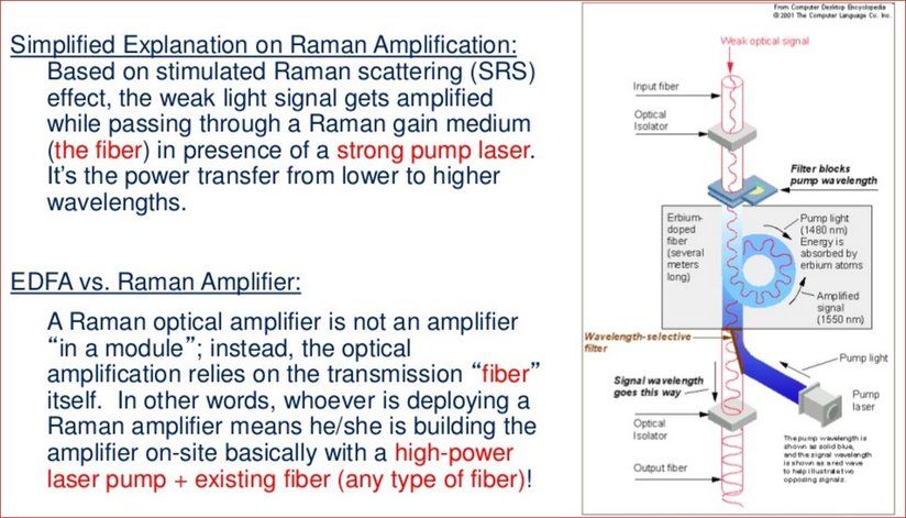
  6. The amplifier works on the principle of Stimulated Raman Scattering (SRS), which is a nonlinear effect.
  7. It consists of a high-power pump laser and fiber coupler (optical circulator).
  8. The amplification medium is the span fiber in a Distributed Type Raman Amplifier (DRA).
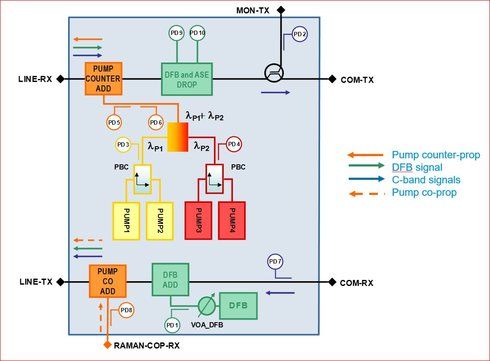
  9. Distributed Feedback (DFB) laser is a narrow spectral bandwidth which is used as a safety mechanism for Raman Card. DFB sends pulse to check any back reflection that exists in the length of fiber. If no High Back Reflection (HBR) is found, Raman starts to transmit.
  10. Generally HBR is checked in initial few kilometers of fibers to first 20 Km. If HBR is detected, Raman will not work. Some fiber activity is needed after you find the problem area via OTDR.

Common Types of Raman Amplifiers

  • The lumped or discrete type Raman amplifier internally contains a sufficiently long spool of fiber where the signal amplification occurs.
  • The DRA pump laser is connected to the fiber span in either a counter pump (reverse pump) or a co-pump (forward pump) or configuration.
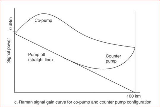
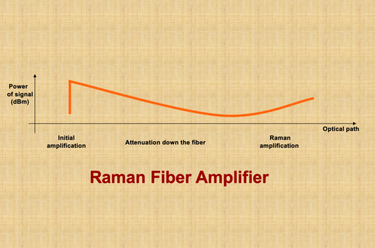
  • The counter pump configuration is typically preferred since it does not result in excessively high signal powers at the start of the fiber span, which can result in nonlinear distortions as shown in the image.

The advantage of the co-pump configurations is that it produces less noise.

Principle

As the pump laser photons propagate in the fiber, they collide and are absorbed by fiber molecules or atoms. This excites the molecules or atoms to higher energy levels. The higher energy levels are not stable states so they quickly decay to lower intermediate energy levels that release energy as photons in any direction at lower frequencies. This is known as spontaneous Raman scattering or Stokes scattering and contributes to noise in the fiber.

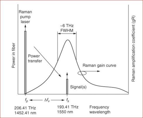
Since the molecules decay to an intermediate energy vibration level, the change in energy is less than the initial received energy at the time of molecule excitation. This change in energy from excited level to intermediate level determines the photon frequency since Δ f = Δ E / h. This is referred to as the Stokes frequency shift and determines the Raman gain versus frequency curve shape and location. The energy that remains from the intermediate level to ground level is dissipated as molecular vibrations (phonons) in the fiber. Since there exists a wide range of higher energy levels, the gain curve has a broad spectral width of approximately 30 THz.

At the time of the stimulated Raman scattering, signal photons co-propagate frequency gains curve spectrum, and acquires energy from the Stokes wave, that results in signal amplification.

Theory of Raman Gain

The Raman gain curve’s FWHM width is about 6THz (48 nm) with a peak at about 13.2THz under the pump frequency. This is the useful signal amplification spectrum. Therefore, in order to amplify a signal in the 1550 nm range the pump laser frequency is required to be 13.2THz below the signal frequency at about 1452 nm.


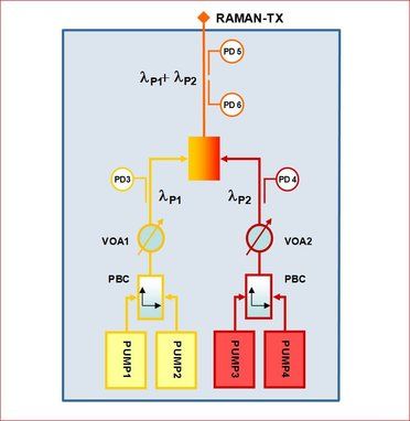
Multiple pump lasers with side-by-side gain curves are used to widen the total Raman gain curve.

Where fp = pump frequency, THz  fs = signal frequency, THz Δ f v = Raman Stokes frequency shift, THz.

Raman gain is the net signal gain distributed over the fiber’s effective length. It is a function of pump laser power, fiber effective length, and fiber area.

For fibers with a small effective area, such as in dispersion compensation fiber, Raman gain is higher. Gain is also dependent on the signal separation from the laser pump wavelength, Raman signal gain is also specified and field measured as on/off gain. This is defined as the ratio of the output signal power with the pump laser on and off. In most cases the Raman ASE noise has little effect on the measured signal value with the pump laser on. However, if there is considerable noise, which can be experienced when the measurement spectral width is large, then the noise power measured with the signal off  is subtracted from the pump on signal power in order to obtain an accurate on/off gain value. The Raman on/off gain is often referred to as the Raman gain.

Noise Sources

Noise created in a DRA span consists:

  • Amplified Spontaneous Emissions (ASE)
  • Double Rayleigh Scattering (DRS)
  • Pump Laser Noise

ASE noise is due to photon generation by spontaneous Raman scattering.

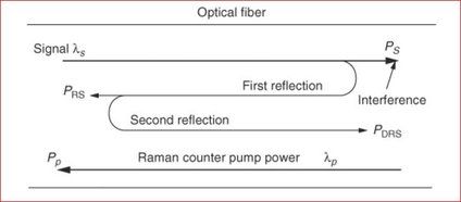
DRS noise occurs when twice reflected signal power due to Rayleigh scattering is amplified and interferes with the original signal as crosstalk noise.

The strongest reflections occur from connectors and bad splices.

Typically DRS noise is less than ASE noise, but for multiple Raman spans it can add up. In order to reduce this interference, Ultra Polish Connectors (UPC) or Angle Polish Connectors (APC) can be used. Optical isolators can be installed after the laser diodes in orer to reduce reflections into the laser. Also, span OTDR traces can help locate high-reflective events for repair.

Counter pump DRA configuration results in better OSNR performance for signal gains of 15 dB and greater. Pump laser noise is less of a concern because it usually is quite low with RIN of better than 160 dB/Hz.

Nonlinear Kerr effects can also contribute to noise due to the high laser pump power. For fibers with low DRS noise, the Raman noise figure due to ASE is much better than the EDFA noise figure. Typically, the Raman noise figure is –2 to 0 dB, which is about 6 dB better than the EDFA noise figure.

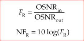
Raman amplifier noise factor is defined as the OSNR at the input of the amplifier to the OSNR at the output of the amplifier.

Noise figure is the dB version of noise factor.

The DRA noise and signal gain is distributed over the span fiber’s effective length.

Counter pump distributed Raman amplifiers are often combined with EDFA pre-amps to extend span distances. This hybrid configuration can provide 6dB improvement in the OSNR, which can significantly extend span lengths or increase span loss budget. Counter pump DRA can also help reduce nonlinear effects and allows for channel launch power reduction.

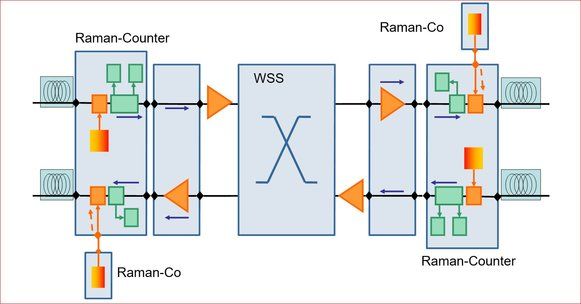
  Functional Block Diagram for CoPropagating and Counter Propagating Raman Amplifier

Field Deployment architecture of EDFA and RAMAN Amplifiers:

Interesting to know:

Related Information