
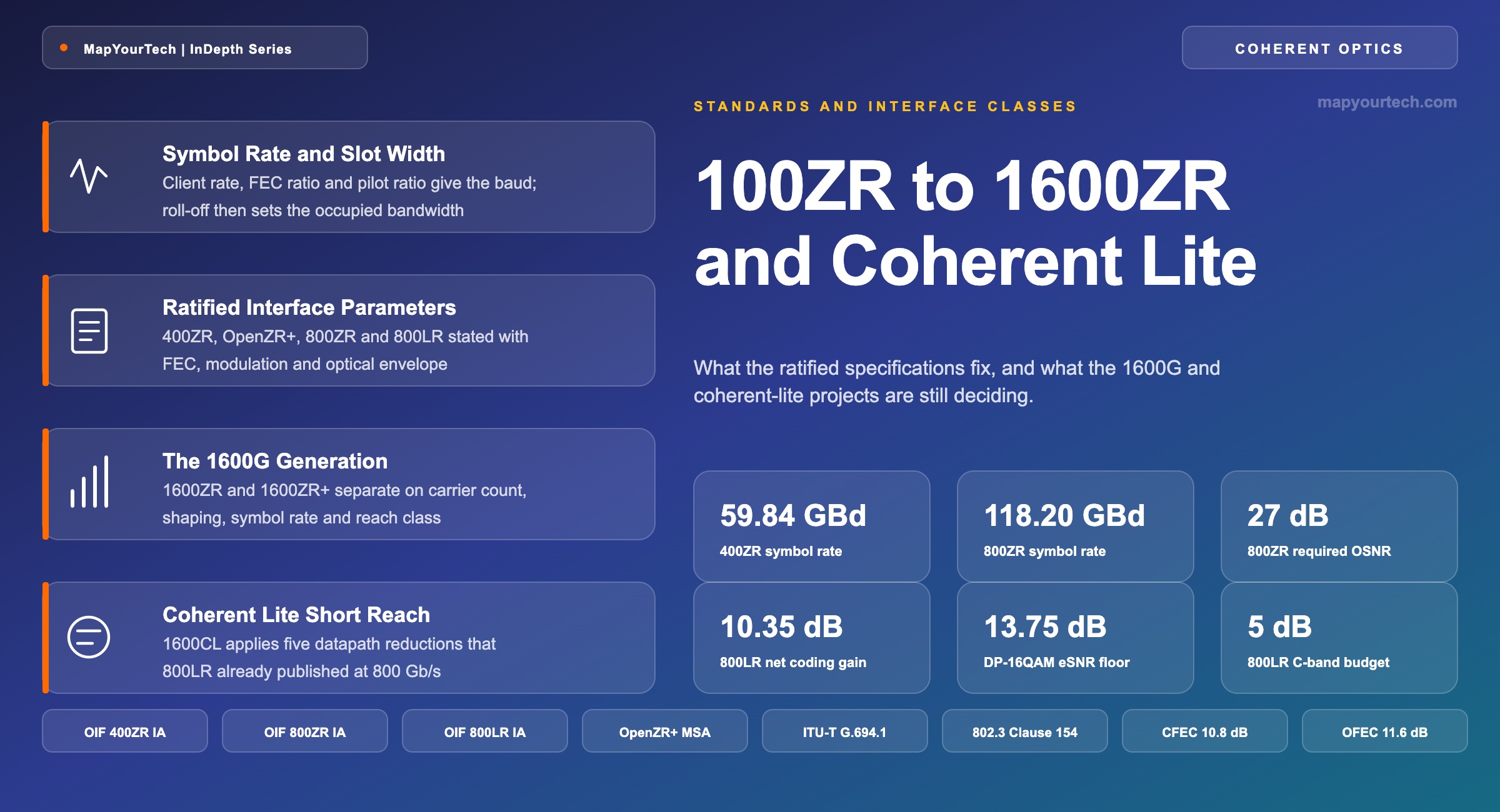
Coherent Pluggable Evolution: 100ZR to 1600ZR and Coherent Lite
What the ratified coherent line-interface specifications fix, what the 1600G and coherent-lite projects are still deciding, and the arithmetic that separates one class from the next.
A standard bounds behaviour; it does not describe performance.
What You Will Learn
- Derive the symbol rate of a coherent line interface from its client rate, FEC ratio and pilot ratio, and reproduce the 123.636 GBd figure the 800LR specification states (Section 2, Figure 1).
- Convert an occupied bandwidth into a flexible-grid slot width and explain why an 800ZR channel needing 125 GHz is provisioned on a 150 GHz spacing (Section 2, Table 1).
- Place every ratified interface class in its application band, from a 5 dB unamplified C-band campus budget to a 120 km amplified single span (Section 3, Figure 2).
- State the FEC, modulation, required OSNR and dispersion tolerance of 400ZR, OpenZR+, 800ZR and 800LR with the evidence class attached to each figure (Section 4, Table 2).
- Convert a 27 dB/0.1 nm required OSNR into the electrical SNR a receiver decision device sees at 118.203 GBd, and compare it against the 13.75 dB DP-16QAM threshold (Section 5).
- Separate 1600ZR from 1600ZR+ on the four parameters that differ — baud rate, subcarrier count, shaping and reach class — and track each against its published project scope (Section 6, Table 3).
- Identify which digital signal processing functions the coherent-lite class removes to reach a 300 ns latency target, and what each removal costs in reach (Sections 7 and 8, Figures 5 and 6).
- Select an interface class against a stated span, client mix, power ceiling and line system using the selection matrix and quick-reference tables (Sections 12 and 14).
1. Introduction
A coherent line interface that once occupied a transponder line card now occupies a faceplate cage, and the specification that defines it is a published Implementation Agreement rather than a vendor datasheet. The Optical Internetworking Forum (OIF) 400ZR Implementation Agreement established the pattern: a single-carrier dual-polarization 16-state quadrature amplitude modulation (DP-16QAM) line at 59.843750000 GBd ±20 ppm carrying one 400GBASE-R client, with concatenated forward error correction (CFEC) and a post-FEC error floor below 1.0 × 10⁻¹⁵ (standard-specified, OIF 400ZR Implementation Agreement). Every class that followed — 100ZR, OpenZR+, 800ZR, 800LR, and the 1600G projects now in progress — reuses that pattern and changes a small number of parameters.
The parameters that change are the ones a network engineer has to defend in a design review. Symbol rate sets the occupied bandwidth and therefore the spectral slot. Forward error correction (FEC) code and overhead set the coding gain and therefore the required optical signal-to-noise ratio (OSNR). Modulation order and shaping set how much of that OSNR a given reach can deliver. Module power sets what a router faceplate can hold. A coherent pluggable is a bounded trade among those four, and each interface class is a different point in the space rather than a different technology.
Three things have changed in this space since the 800G generation reached volume. The OIF has published an 800LR Implementation Agreement for unamplified single-wavelength campus links up to 10 km, which is the first coherent interface written to compete with intensity-modulation direct-detection (IM-DD) client optics on density and power rather than on reach. The 1600ZR and 1600ZR+ projects have passed their digital baselines and moved into the implementation-agreement phase, with vendors sampling against draft baselines. And a third project, 1600CL, has opened a short-reach coherent class positioned between the campus interface and the data-center-interconnect (DCI) interface, with power and latency as its primary objectives rather than reach.
This article states what each interface class fixes, derives the arithmetic that connects client rate to symbol rate to slot width, and separates the ratified specifications from the projects still deciding their parameters. Every figure carries its evidence class in the same sentence: standard-specified where a published Implementation Agreement or Recommendation states it, industry-reported where it comes from a conference briefing or analyst publication, vendor claim where it comes from a supplier, and derived where this article computes it. The scope is terrestrial pluggable coherent interfaces on Ethernet clients. Embedded transponder engines, submarine line terminal equipment and the router-side architecture that hosts these modules are treated separately in the MapYourTech walkthrough of IP-over-DWDM architecture.
2. Symbol Rate and Slot Width Definitions
The symbol rate of a coherent line interface is the number of modulation symbols the transmitter emits each second, expressed in baud and written GBd for 109 symbols per second. It is fixed by the client rate the interface carries, multiplied by every overhead ratio the line adds, divided by the number of bits each symbol conveys. Symbol rate sets the analog bandwidth of the transmitter, the noise bandwidth of the receiver, and the width of spectrum the channel occupies.
That definition matters because the symbol rate is the single number from which most of a coherent interface's optical behaviour follows. Baud is not a marketing figure attached to a generation; it is an arithmetic consequence of three design decisions that are each recorded in the specification, and it can be reproduced exactly from the published overhead ratios.
Read the Full Analysis with Premium
The remaining 89% of this article — the design numbers, trade-offs and field guidance — is part of MapYourTech Premium, along with the full premium library, courses and professional tools.
You May Also Like

-
Free
-
September 4, 2026

-
Premium
-
September 4, 2026

-
Premium
-
September 4, 2026