IP over DWDM: A Complete Architecture Walkthrough
From coherent routers and passive multiplexers through ROADMs, amplifiers, and open line systems — with the per-span OSNR design target and the physics that ends the architecture at long reach.
1. Introduction
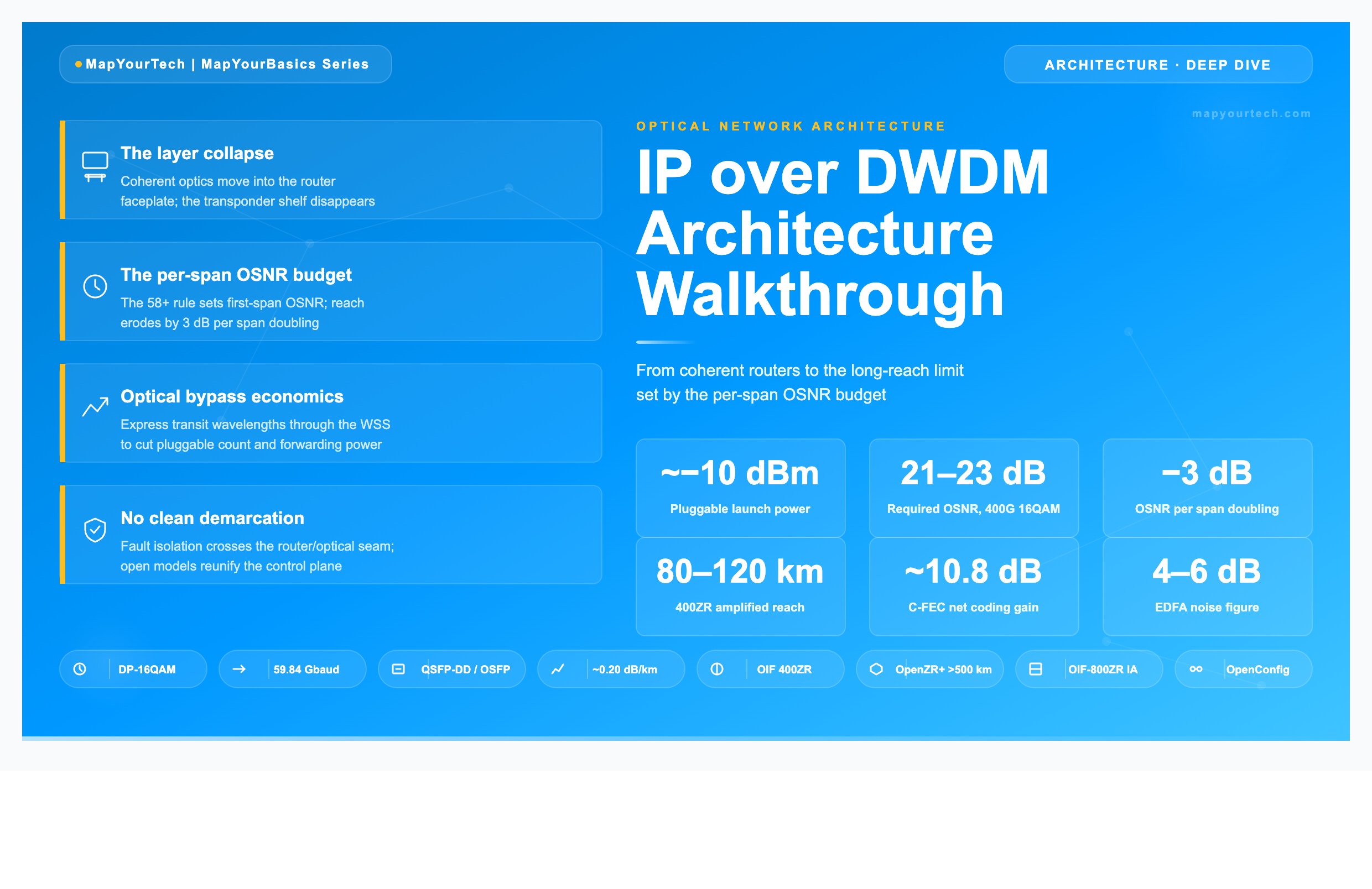
A traditional core network carries three stacked hardware layers between two routers: the IP router itself, a transponder shelf that converts the router's grey client signal into a coherent DWDM wavelength, and an optical line system that multiplexes, amplifies, and routes that wavelength across the fiber. IP over DWDM (IPoDWDM) removes the middle layer. The coherent transponder shrinks into a QSFP-DD or OSFP pluggable module that seats directly in the router faceplate, generating an ITU-grid wavelength at the router port. The transponder shelf, its chassis, its power supplies, and its management plane all disappear.
This collapse is the reason the architecture matters to anyone designing a backbone today. Removing the transponder layer cuts the equipment count, the rack space, the power draw, and the number of management domains an operator runs. Published operator results put the savings in concrete terms: one converged packet-optical design cut router and transponder hardware count by roughly 40%, reduced floor space by about 77%, and dropped power by about 54%. These are not marginal gains — they change the economics of building capacity.
The architecture is enabled by a specific class of optics. The coherent pluggable that fits into a router line card packs a complete coherent optical engine — tunable laser, dual-polarization modulator, balanced receiver, and a coherent digital signal processor — into a module measuring 72 mm by 18 mm by 8.5 mm. The OIF 400ZR Implementation Agreement, published in 2020, was the first standard to define such a module for multi-vendor interoperability. The DSP inside the module handles every fiber impairment that a transponder used to handle: chromatic dispersion, polarization-mode dispersion, frequency offset, and phase noise.
The catch is that IPoDWDM does not change the physics of the fiber. A coherent pluggable launches at a much lower power than a line-card transponder — often around −10 dBm versus the 0 to +1 dBm of a bright transponder — and that single number propagates through every design decision in this article. It sets the optical signal-to-noise ratio (OSNR) the receiver sees, it bounds the number of amplified spans the link can cross, and it is the reason the architecture has a hard reach ceiling that a transponder-based network does not. This article walks the complete signal path, derives the per-span OSNR budget that governs reach, and identifies the exact point where the architecture stops working and a different design is required.
Scope. This walkthrough covers the terrestrial IPoDWDM signal path end to end: the coherent router port, the passive mux or ROADM, the EDFA chain, and the open line system controller. It derives the OSNR budget from the ASE-noise physics rather than quoting a target, and it states the reach boundary in measurable terms — required OSNR at the FEC limit versus delivered OSNR after N spans. It does not cover submarine systems, which use different repeater spacing and power budgets.
2. Fundamentals: Collapsing Two Layers into One
Coherent detection is the technology that made the router-hosted transponder possible. A coherent receiver mixes the incoming optical signal with a local-oscillator laser, downconverting the optical field to electrical baseband where both amplitude and phase survive. That recovered field carries four independent dimensions — in-phase and quadrature on each of two orthogonal polarizations — so a single wavelength can carry four bits per symbol on DP-16QAM, or eight on DP-64QAM. Direct-detection optics see only intensity and recover one dimension. The four-dimensional encoding is what lets a 75 GHz channel carry 400 Gbps.
The coherent DSP is the second enabling piece. Before coherent DSP, chromatic dispersion was managed in the optical domain with bulky dispersion-compensating fiber modules placed at every amplifier site. The DSP moves all of that into silicon: it applies a digital filter that inverts the fiber's accumulated dispersion, tracks and removes the transmitter-receiver frequency offset, follows laser phase noise, and adaptively equalizes polarization rotation. Removing the optical dispersion-compensation modules is what allows a coherent wavelength to run on any ITU-grid frequency without per-wavelength hardware — the property the industry calls colorless operation.
2.1 The three-layer model and what IPoDWDM removes
A conventional transport network stacks three distinct hardware layers between routers. The IP router forwards packets and presents a grey client interface, typically 400GbE on a QSFP-DD. A transponder or muxponder shelf receives that grey signal and generates a coherent DWDM wavelength, adding its own chassis, power, cooling, and element-management system. The optical line system — multiplexers, amplifiers, and ROADMs — then carries the wavelength across the fiber plant.
IPoDWDM removes the transponder shelf by placing the coherent optics inside the router. The router line card hosting QSFP-DD or OSFP coherent modules generates the ITU-grid wavelength directly. The grey-to-coherent conversion stage no longer exists as separate hardware. What remains is two layers: routers carrying coherent optics, and a simplified line system carrying those wavelengths. The router's network processor handles framing; the module's DSP handles fiber impairments. The handoff between them happens on an electrical interface inside the faceplate, the 400GAUI-8 interface defined for 400ZR.
2.2 The standards framework
Three standards bodies define the modules and the framing. The OIF 400ZR Implementation Agreement fixes a 400GbE-only interface using DP-16QAM at a symbol rate of 59.84375 Gbaud, with Concatenated FEC and a reach objective of 80 to 120 km on amplified links. The OpenZR+ Multi-Source Agreement extends the same form factor with higher-gain open FEC (oFEC) and flexible line rates of 100, 200, 300, and 400 Gbps, reaching well beyond 500 km. ITU-T G.709 defines the optical transport network framing — the OPU, ODU, and OTU wrappers — that a true IPoDWDM router supports for FEC and optical-path monitoring.
The two FEC schemes set the reach split between the standards. The 400ZR Concatenated FEC combines an outer hard-decision staircase code, RS(255,239), with an inner soft-decision Hamming code, (128,119), delivering a net coding gain of approximately 10.8 dB at a post-FEC bit error rate of 1.0×10⁻¹⁵ from a pre-FEC threshold of 1.25×10⁻². The FEC overhead is approximately 14.8%. OpenZR+ uses a stronger open FEC with a net coding gain of roughly 11.1 to 11.6 dB, and that extra coding gain — under 1 dB — is most of the difference between a 120 km module and a 1,000 km module.
Takeaway: IPoDWDM removes the transponder shelf, not the optical line system. Coherent detection plus the DSP is what shrinks the transponder into a faceplate module, and the FEC net coding gain — 10.8 dB for 400ZR C-FEC, up to 11.6 dB for OpenZR+ oFEC — is the single parameter that separates a short-reach DCI module from a regional one.
3. Technical Architecture: The Full Signal Path
An IPoDWDM link looks to the routing protocol like an ordinary high-speed point-to-point connection. Below that abstraction sits the same optical chain as any DWDM system, with the router's coherent port as the terminal interface. The signal path runs from the router pluggable, through a passive multiplexer or a ROADM add port, into an amplified fiber span, across any number of intermediate amplifier or ROADM sites, and into the far-end router pluggable. The diagram below traces a single wavelength across two spans with a ROADM at the mid-point.
3.1 The coherent router port
The pluggable module is both the client interface and the line interface. On the host side it presents a 400GAUI-8 electrical lane group to the router's network processor; on the line side it emits a single tunable DWDM wavelength across the C-band, from 191.3 to 196.1 THz, on either the 100 GHz or 75 GHz ITU-T fixed channel grid defined in the ITU grid that governs DWDM channel spacing. The module's DSP performs every impairment-compensation function: it digitally compensates chromatic dispersion of D×L picoseconds per nanometer, tracks polarization-mode dispersion, removes the transmitter-to-local-oscillator frequency offset, and adaptively equalizes the channel.
The launch power is the parameter that constrains the rest of the architecture. A standard 400ZR pluggable launches near −10 dBm, far below the 0 to +1 dBm of a line-card transponder. That deficit is structural: the module's power envelope — 400ZR targets roughly 15 W, 400ZR+ holds to 25 W — leaves little budget for a high-power output stage. A few module classes embed an output amplifier to reach 0 dBm, and the multi-vendor testbeds distinguish high-power (HP) from low-power (LP) variants precisely because the launch power sets the OSNR at the first span and therefore the multi-span margin.
3.2 The multiplexer or ROADM
Two combining strategies exist, and the choice defines the topology. A passive mux/demux pair simply combines the router's colored wavelengths onto one fiber and separates them at the far end, using arrayed-waveguide gratings or thin-film filters with 3 to 5 dB insertion loss. This is the right choice for point-to-point DCI and for low-capacity rings and chains, where there is no transit traffic to route. It adds no optical-layer intelligence: a fiber break is recovered entirely by the IP routing layer.
A ROADM replaces the passive mux with a wavelength-selective switch (WSS), turning the node into a software-controlled router for wavelengths. The colorless, directionless, and contentionless ROADM that adds or drops any wavelength on any port enables ring and mesh topologies and, more importantly, optical bypass. A wavelength carrying transit traffic can express straight through an intermediate node's WSS without entering the router, which removes the cost and power of a coherent pluggable at every hop and removes the energy of forwarding that traffic inside the router. Optical bypass is the single design move that makes IPoDWDM scale economically at high traffic levels.
The low launch power complicates ROADM use. A high-degree ROADM applies WSS insertion loss of 6 to 9 dB at the add port, and starting from −10 dBm there is little margin left to feed the booster. This is why high-degree ROADM designs with low-power pluggables typically require an add-path amplifier, or a higher-power "colorable" module, to present enough power to the line system.
3.3 Amplifiers and the open line system
Because the launch power is low and fiber attenuates at about 0.2 dB/km, every span needs amplification. An EDFA whose gain must be flattened across the C-band compensates the roughly 16 to 20 dB loss of an 80 to 100 km span, with a noise figure of 4 to 6 dB. On the longest spans a Raman pump is added ahead of the EDFA to lower the effective noise figure through distributed gain. The amplifier chain is what carries the signal, and it is also what limits it: every EDFA adds amplified spontaneous emission (ASE) noise, and that accumulation is the subject of the next section.
Many operators run the optical layer as a disaggregated open line system (OLS) sourced from a different vendor than the routers. The open line system that carries multi-vendor coherent wavelengths consists of the amplifiers, filters, and ROADMs plus an independent controller with a northbound API — typically NETCONF with YANG models, or the Transport-API. The OLS publishes the spectrum it carries, the launch-power window it expects at each add port, and the OSNR it delivers at each drop port. This contract is what lets a Cisco router feed a Ciena or Adtran line system without vendor lock-in, and it is the operational seam where IPoDWDM responsibility splits between the router team and the optical team.
Takeaway: The signal path is the same DWDM chain a transponder network uses, but the −10 dBm launch power changes the design at every element — it limits the add-path budget through a ROADM, it forces amplification on every span, and it sets the first-span OSNR that the multi-span budget builds on. The OLS contract (launch-power window in, OSNR out) is the demarcation between the router and optical domains.
4. Design Considerations: The Per-Span OSNR Budget
OSNR sets the upper bound on the modulation order a coherent link can carry. Drop below the OSNR threshold for DP-16QAM and the link fails its post-FEC bit error rate target; the practical response is to fall back to a lower-order format or a lower line rate, halving spectral efficiency on that wavelength. For a 400G DP-16QAM signal the required OSNR sits around 21 to 23 dB; 100G DP-QPSK tolerates 13 to 15 dB. The design problem in IPoDWDM is to deliver more OSNR at the receiver than the module requires at its FEC limit, across the full span count, starting from a low launch power. This section derives the budget from the ASE physics rather than quoting a target.
4.1 Where the noise comes from
Every EDFA generates amplified spontaneous emission. Erbium ions pumped to an excited state decay spontaneously as well as by stimulated emission, and those spontaneous photons are themselves amplified, producing a noise floor across the amplifier's gain band. The ASE power scales with the gain, the inversion efficiency, and the optical bandwidth:
P_ASE = 2 · n_sp · (G − 1) · h · ν · B

Where:
  P_ASE = amplified spontaneous emission power (W)
  n_sp  = spontaneous emission (population inversion) factor
  G     = amplifier gain (linear)
  h     = Planck constant (6.626 × 10^−34 J·s)
  ν     = optical frequency (Hz), ~193.4 THz in the C-band
  B     = optical reference bandwidth (Hz)

Noise figure relation:  NF ≈ 2 · n_sp   (best case 3 dB at full inversion)
Practical EDFA noise figure: 4–6 dB
The noise figure is the engineering handle on this physics. A fully inverted EDFA reaches the 3 dB quantum limit; deployed C-band amplifiers run 4 to 6 dB. A lower noise figure means less ASE per amplifier, which is why the most OSNR-sensitive channels are placed near the EDFA gain peak around 1550 to 1555 nm, and why ultra-long spans add Raman amplification — the distributed Raman gain produces an effective noise figure that can fall below 0 dB because it amplifies the signal before fiber attenuation has degraded it.
4.2 The single-span OSNR contribution
For a chain of amplified spans where each amplifier exactly recovers its preceding span loss, the OSNR contributed by one span follows the standard amplified-link relation. Stated in decibels with a 0.1 nm (12.5 GHz) reference bandwidth, the per-span OSNR is:
OSNRspan = P_out − L − NF − 10log(hν·ν_r)

Where:
  OSNR_span = per-span OSNR contribution (dB, in 0.1 nm)
  P_out     = per-channel launch power into the span (dBm)
  L         = span loss (dB) = amplifier gain that recovers it
  NF        = amplifier noise figure (dB)
  10log(hν·ν_r) = −58.0 dBm  for ν = 193.4 THz, ν_r = 12.48 GHz (0.1 nm)

Reduces to:  OSNR_span ≈ 58 + P_out − L − NF   (the "58 + " rule)
The constant −58.0 dBm is the photon-energy term evaluated at the C-band center for a 0.1 nm reference bandwidth, and it is why operators speak of the "58 plus" rule. The structure of the equation makes the IPoDWDM penalty visible at a glance: Pout appears with a positive sign, so the low pluggable launch power directly subtracts OSNR at every span relative to a bright transponder. A transponder launching at 0 dBm starts each span roughly 10 dB ahead of a −10 dBm pluggable on this single term.
4.3 Accumulation over N spans
OSNR is a ratio, so it accumulates as the inverse-sum of the per-span linear values. When every span delivers the same OSNRspan, the closed form is a clean logarithmic penalty in the span count:
1 / OSNRtotal = Σ (1 / OSNRspan,i)        (linear)

For N identical spans:
  OSNRtotal = OSNRspan − 10·log10(N)   (dB)

Adding 1 span beyond 1:   −3.0 dB   (N = 2)
Going from 1 to 10 spans: −10.0 dB
Going from 1 to 15 spans: −11.8 dB
This −10·log10(N) term is the spine of every IPoDWDM reach calculation. Doubling the span count costs 3 dB of OSNR; reaching ten spans costs 10 dB. The receiver's required OSNR at the FEC limit is fixed by the module's coherent sensitivity — multi-vendor testbeds confirm that high-power and low-power variants of the same pluggable share the same required OSNR, because launch power changes delivered OSNR but not receiver sensitivity. Reach ends at the span count where delivered OSNRtotal falls to the required OSNR plus the design margin.
Practical Example — 400G OpenZR+ across a regional route
Consider a 400G DP-16QAM OpenZR+ wavelength on a regional route built from 80 km spans of standard single-mode fiber, with a high-power pluggable embedding a small output amplifier so it presents about −1 dBm per channel into the booster.
Given:
  Per-channel launch power  P_out = −1 dBm
  Span length               80 km × 0.20 dB/km = 16 dB loss
  Amplifier noise figure     NF = 5 dB
  Required OSNR (400G 16QAM, oFEC) ≈ 21 dB
  Design margin              3 dB  → target delivered OSNR = 24 dB

Single-span OSNR (58+ rule):
  OSNR_span = 58 + (−1) − 16 − 5 = 36 dB

Accumulation to required-OSNR-plus-margin (24 dB):
  Allowed penalty = 36 − 24 = 12 dB
  12 = 10·log10(N)  →  N = 10^1.2 ≈ 16 spans

Reach estimate:
  16 spans × 80 km ≈ ~1,280 km  (OSNR-limited, before
  nonlinear and filtering penalties are deducted)
The OSNR budget alone suggests roughly 1,280 km, consistent with OpenZR+ regional reach claims. Two effects pull the real number down. Nonlinear interference — self-phase modulation, cross-phase modulation, and four-wave mixing — behaves as an additional noise term that grows with launch power, so the OSNR-versus-power curve has a peak rather than rising forever. Cascaded WSS filtering narrows the effective passband at each ROADM; measurements on 110 Gbaud systems show the 3 dB passband narrowing from about 94.8 GHz to 84.5 GHz after ten ROADM cascades, clipping the signal edges and adding penalty. The real reach is where delivered OSNR minus all penalties equals required OSNR.
4.4 Visualizing the accumulation
The chart below plots delivered OSNR against span count for two starting points: a low-power pluggable near −10 dBm and a high-power variant near −1 dBm, both on 80 km spans with 5 dB noise-figure amplifiers. The horizontal line marks the 24 dB target (21 dB required plus 3 dB margin) for 400G DP-16QAM. The span count where each curve crosses that line is the OSNR-limited reach boundary.
Figure 5: Delivered OSNR versus span count. The high-power pluggable starts ~9 dB higher and crosses the 24 dB target many spans later than the low-power module — the launch-power deficit translates directly into a reach deficit through the 58+ and −10·log(N) terms.
Takeaway: Reach in IPoDWDM is governed by two terms. The 58+ rule sets the first-span OSNR and is dominated by launch power, where the −10 dBm pluggable starts ~10 dB behind a bright transponder. The −10·log10(N) term then erodes OSNR by 3 dB per span doubling. The architecture works wherever delivered OSNR stays above required OSNR plus margin; it ends, abruptly, at the span count where they meet.
5. Implementation: Turning Up a Link
The simplest IPoDWDM deployment, direct connect, turns up like client optics. Two routers connect through small-form-factor pluggables and a low-insertion-loss passive mux, with no optical-layer intelligence between them. For DCI links under 40 km, an unamplified dark-fiber span with roughly a 10 dBm loss budget is often enough; the modules auto-negotiate the DWDM channel and the link comes up plug-and-play with zero-touch provisioning. Recovery from a fiber break is handled entirely by the IP layer, typically by segment-routing fast reroute that restores traffic in milliseconds.
5.1 Provisioning the optical channel
An amplified or ROADM-based link requires the optical layer to be commissioned before the wavelength carries traffic. The launch power per channel must land inside the window the OLS publishes for each add port. The booster EDFA runs at saturation for the best noise figure, and a variable optical attenuator after it sets the exact per-channel launch power into the span — both the signal and the EDFA ASE are attenuated equally by the VOA, so this power-setting step preserves OSNR through the node. As ROADMs add and drop wavelengths and the channel count changes, the VOA attenuation is recalculated to hold the per-channel target.
The wavelength itself is set on the module. The pluggable tunes to the assigned ITU-grid frequency, and the line system's WSS is configured to pass that frequency along the intended path. Across a multi-span network, commissioning uses optical channel monitor and optical spectrum analyzer data in sequence to confirm per-channel power and OSNR before the service is declared up. The router, meanwhile, treats the optical channel as a link it must bring into its routing topology — the two provisioning workflows run in parallel and meet at the module.
5.2 Configuration through the CMIS interface
The host configures the pluggable through the Common Management Interface Specification. The module exposes application-select profiles — a 400G 60 Gbaud 16QAM oFEC profile, a 100G 25 Gbaud DP-QPSK profile, and others — and the router selects the one matching the link's rate and reach. Multi-vendor testbeds run modules from different suppliers using their CMIS application-select profiles and report increasing maturity of the CMIS 5.x implementations, which is the practical prerequisite for a true open ecosystem where any compliant module works in any compliant port.
5.3 Validation and testing
Validation confirms two numbers: the delivered OSNR meets the required OSNR with margin, and the pre-FEC bit error rate stays below the module's FEC threshold. Multi-vendor field validation across six ROADM nodes over 480 km demonstrated error-free 400G operation, with OSNR degradation per span following the expected ROADM filtering and amplifier-noise behavior. The back-to-back OSNR curves of all tested modules converged to the same FEC-limited breaking point independent of transmit power — direct confirmation that required OSNR is a receiver property, not a launch-power property. The pre-FEC BER reading is the live margin indicator: a module running well below its 1.25×10⁻² threshold has headroom; one approaching it is near its reach limit.
Takeaway: Direct-connect links turn up like client optics; amplified and ROADM links require the optical layer commissioned first — launch power set by a post-EDFA VOA inside the OLS window, wavelength tuned and WSS configured, OSNR and pre-FEC BER validated. CMIS application-select profiles are how the router drives the module, and CMIS maturity is the gate on genuine multi-vendor interchangeability.
6. Performance and Analysis: Monitoring the Converged Link
The converged architecture splits monitoring across two domains that used to be one. The router sees the link as an interface with a packet error rate and a coherent module reporting digital optical monitoring: received power, OSNR estimate, and pre-FEC BER. The optical line system sees wavelengths, amplifier gains, and span OSNR through its OCMs. Neither domain alone has the full picture, which is the central operational challenge of IPoDWDM — fault isolation crosses the router/optical seam.
6.1 What the module reports
The pluggable's digital optical monitoring gives the first line of analysis. Received power below the expected drop-port value points to span loss, a dirty connector, or amplifier degradation upstream. A rising pre-FEC BER with stable received power points to OSNR erosion or a nonlinear or filtering penalty rather than a power problem. The module's OSNR estimate, cross-checked against the OLS's OCM reading at the drop port, localizes whether the degradation is in the wavelength or in the line system. These three numbers — power, OSNR, pre-FEC BER — are the working diagnostic set.
6.2 OSNR monitoring across the line system
The line system's optical channel monitors that report per-channel OSNR continuously are how an operator catches degradation before traffic is hit. A worked monitoring case makes the thresholds concrete: a 1,200 km system of 15 spans averaging 80 km with 5.5 dB noise-figure inline EDFAs and −3 dBm per-channel launch delivers a single-span OSNR near 38 dB, accumulating to about 38 − 10·log10(15) ≈ 26 dB at the receiver. An NMS configured to warn below 23 dB — the required-plus-3 dB margin point — and to raise a critical alarm below 20 dB gives the operations team a diagnostic window before the FEC limit is reached.
6.3 Managing the amplifier chain
Performance over a mixed-rate line system depends on holding every channel inside its power and OSNR range as loading changes. EDFA gain is not flat across the C-band — raw gain varies 3 to 5 dB between the 1530 nm peak and the 1560 nm region — and that ripple compounds across spans. Mitigation places the most OSNR-sensitive channels near the gain peak, uses amplifiers with under 1 dB peak-to-peak ripple, and applies per-channel power monitoring with VOAs at ROADM add ports. When channels are added or removed, surviving channels see transient power excursions as the EDFA automatic gain control adjusts; gain-clamped designs with sub-millisecond AGC response keep those transients from causing error bursts on channels with tight OSNR margins. The planning of mixed channel rates on a shared line system is where these interactions are designed out before they reach the field.
Takeaway: Monitoring spans two domains. The module reports received power, OSNR, and pre-FEC BER; the OLS reports per-channel OSNR through OCMs. The diagnostic skill is reading both together to localize a fault across the router/optical seam — rising pre-FEC BER with stable power means OSNR or penalty, not loss. NMS alarm thresholds at required-plus-margin (warn) and just above the FEC limit (critical) give the window to act before traffic drops.
7. Operations and Resiliency: Managing a Network Without a Clean Demarcation
A transponder-based network has a hard boundary between teams. The optical group owns the WDM gear and transponders through a vendor element-management system; the IP group owns the routers. A link fault lands in one domain or the other, and the demarcation point tells the operator which team starts troubleshooting. IPoDWDM erases that boundary. The router owns the optical interface, so a single link failure could be a fiber cut, an amplifier fault, a dirty connector, or the router's own pluggable — and there is no demarcation point to assign it. This is the operational cost that pays for the CAPEX and power savings, and it is the most common reason large-scale adoption stalls in carrier networks.
7.1 Fault isolation across the seam
Fault isolation in a converged network requires correlating alarms from both layers in one place. When an IP link drops, the diagnostic does not stop at the router — it has to check the optical alarms on that wavelength: loss of signal at the drop port, an amplifier failure, or an OSNR alarm from an OCM. The three module readings established earlier — received power, OSNR, and pre-FEC BER — are the entry point, but the root cause often sits in the line system the router cannot see directly. The flowchart below shows the decision path an operator follows when a converged link degrades.
7.2 The open-models control plane
The answer to the demarcation problem is a control plane that sees both layers at once. A hierarchical SDN controller consolidates router and optical state into a single multi-layer view, using vendor-neutral data models to read and configure equipment from different suppliers. OpenConfig provides the device models for transceivers and routers; NETCONF and gNMI carry the configuration and streaming telemetry; the ONF Transport-API exposes the optical line system's topology and services northbound. A multi-vendor field validation built exactly this stack — OpenConfig, NETCONF/gNMI, and ONF T-API into a hierarchical controller — and confirmed it could deliver coordinated IP-and-optical provisioning and end-to-end visibility across vendors. The same validation flagged the live constraint: CMIS maturity. The CMIS 5.x application-select profiles that let any compliant module run in any compliant host are the practical gate on true multi-vendor interchangeability, and that maturity is still being proven in the field.
The barrier that remains is operational-mode abstraction. A pluggable or transponder often exposes its proprietary transmission mode as an opaque attribute the SDN controller cannot interpret, which limits how much the controller can reason about reach and margin across vendors. Standardization work is closing this gap, but until a controller can read every vendor's mode as structured data, the operator carries the integration and modeling effort that a single-vendor turnkey system would have absorbed. This is the concrete shape of the "added integration effort" that offsets the CAPEX win.
7.3 Protection: IP layer versus optical layer
Resiliency in IPoDWDM defaults to the IP layer, and for most traffic that is the right choice. A fiber break on a converged link brings the wavelength down, and IP fast reroute — segment-routing TI-LFA or MPLS FRR — restores traffic in milliseconds by steering packets onto a diverse path, faster than most optical-layer protection and using existing router functionality. In a direct-connect design with passive muxes, this is the only protection available, because the optical layer has no switching intelligence to offer. The table below compares the resiliency options an IPoDWDM operator chooses among.
| Mechanism | Layer | Recovery time | Cost / resource | Where it fits |
|---|---|---|---|---|
| IP fast reroute (SR TI-LFA / MPLS FRR) | IP | Milliseconds | Spare IP capacity on a diverse path; no extra optics | Default for IPoDWDM; only option on passive-mux direct connect |
| Optical 1+1 protection | Optical | Sub-50 ms | Dedicated protection wavelength + photonic switch per channel | Highest-priority circuits where dedicated hardware is justified |
| Optical restoration (control-plane) | Optical | Seconds to tens of seconds | Shared spare spectrum; ROADM switching | Restoring full capacity before the next failure; historically single-vendor |
| ROADM tandem protection | Optical | Sub-second | ROADM ring with bypass; amplifiers tuned for low power | Ring topologies needing fiber-cut protection below the IP layer |
The design choice is whether to add optical protection on top of IP reroute. Optical 1+1 duplicates the signal onto a diverse path and selects the better copy at the receiver, recovering in under 50 ms but requiring a dedicated protection wavelength and a photonic switch per channel — expensive enough that it is reserved for the highest-priority circuits. Optical restoration dynamically reroutes wavelengths after a failure using ROADM switching and shared spare spectrum; it is slower, in the tens of seconds, and its purpose is to restore full capacity before a second failure rather than to protect any single packet. The historical limit is that optical restoration has worked mainly inside closed single-vendor line systems, which is exactly the lock-in IPoDWDM tries to avoid — so most converged designs lean on IP reroute and add optical protection only where a service contract demands sub-50 ms recovery.
Takeaway: IPoDWDM trades a clean demarcation point for CAPEX and power savings, and the bill comes due in fault isolation and multi-vendor integration. The fix is an open-models control plane — OpenConfig, NETCONF/gNMI, ONF T-API into a hierarchical SDN controller — gated by CMIS maturity and held back by opaque vendor transmission modes. Resiliency defaults to millisecond IP fast reroute; optical 1+1 or restoration is added only where a contract justifies the dedicated hardware.
8. Comparison: Where IPoDWDM Wins and Where It Does Not
The choice between IPoDWDM and a transponder-based network is a reach-and-service decision, not a blanket one. The pluggable's low launch power and its Ethernet-centric framing make it ideal for one set of routes and a poor fit for another. The table below compares the dominant module standards and the traditional OTN transponder path.
| Characteristic | 400ZR (OIF IA) | OpenZR+ (MSA) | 800ZR (OIF IA) | OTN transponder (G.709) |
|---|---|---|---|---|
| Primary purpose | Interoperable 400G DCI interface | Extended-reach flexible coherent interface | Interoperable 800G DCI interface | Multi-service transport framing and management |
| Standards body | OIF | Industry MSA | OIF | ITU-T |
| Line rates | 400 Gbps | 100 / 200 / 300 / 400 Gbps | up to 800 Gbps aggregate | ODU0–4, ODUflex, OTUCn |
| Modulation at top rate | DP-16QAM | DP-16QAM (DP-8QAM in Rev 3.0) | DP-16QAM | Transponder-specific (16/32/64QAM, PCS) |
| FEC | C-FEC (staircase + Hamming) | oFEC (high-gain SD) | oFEC | GFEC baseline; modern SD-FEC |
| FEC net coding gain | ~10.8 dB | ~11.1–11.6 dB | ~11+ dB | GFEC ~6.2 dB; HP-FEC 10–12+ dB |
| Max amplified reach | 80–120 km | >500 km, 1000s km at lower rate | 80–120 km (single span) | System-dependent; long-haul to subsea |
| Client interfaces | 400GbE only | 100 / 200 / 400GbE (incl. muxing) | 100GbE up to 800G aggregate | Ethernet, SDH, FC, IP, CBR |
| OAM depth | Basic DOM | Basic DOM | Basic DOM | Extensive multi-layer (PM, TCM, GCC) |
| IPoDWDM role | Key enabler (router-hosted) | Key enabler (router-hosted) | Key enabler (router-hosted) | Not applicable (separate transponder) |
8.1 Selection criteria
The decision rests on three questions. First, reach: a route that fits inside the OSNR budget of a pluggable — single-span DCI for 400ZR/800ZR, regional multi-span for OpenZR+ — is a natural IPoDWDM fit. A transcontinental or submarine route that exceeds the pluggable's OSNR-limited span count needs a bright transponder with a higher launch power and a stronger FEC, or optical-electrical-optical regeneration. Second, services: a route carrying only Ethernet suits the ZR family's Ethernet-only framing; a route that must groom SDH, Fibre Channel, or sub-rate ODU clients needs OTN framing and its multiplexing hierarchy. Third, manageability: OTN's multi-layer OAM — performance monitoring, tandem connection monitoring, fault isolation across a clear demarcation — is richer than the basic digital optical monitoring a pluggable offers, which matters on routes where a hard transport demarcation is contractually required.
8.2 The economic crossover
Direct-connect IPoDWDM is cheapest at low node counts and low transit traffic, where every router forwards all traffic and the absent transponder shelf is pure savings. As the node count and transit traffic grow, forwarding everything through routers becomes the expensive option — each transit hop burns a coherent pluggable and router-forwarding energy. This is the crossover where ROADM-enabled optical bypass wins: expressing transit wavelengths through the WSS instead of the router cuts pluggable count and forwarding power, and the architecture scales more cost-effectively at high traffic. One analyst caution stands: on a line system carrying many channels, the operational cost of running the converged layers can exceed traditional transport, so the management model has to be designed, not assumed.
Takeaway: IPoDWDM wins on Ethernet-centric routes that fit a pluggable's OSNR budget — DCI for 400ZR/800ZR, regional for OpenZR+ — and on low-node direct-connect designs. It loses on routes needing multi-service grooming, deep OTN OAM, or reach beyond the pluggable's span count. ROADM optical bypass is the move that keeps it economical as transit traffic grows.
9. Future Directions: 800ZR, 1.6T, and the Reach Gap
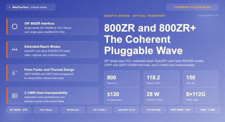
The OIF published the 800ZR Implementation Agreement, OIF-800ZR-01.0, in October 2024, defining a single-wavelength 800G coherent line interface and frame format for single-span amplified DWDM links of 80 to 120 km, aimed at data center interconnect. It specifies Ethernet client interfaces from 100GbE up to 800G aggregate, uses oFEC, and runs DP-16QAM in the same compact pluggable form factors as 400ZR. The OIF demonstrated the first multi-vendor 800ZR interoperability at ECOC 2024 and has since published interoperability study results from an OFC 2025 plugfest, cross-connecting modules from multiple suppliers and measuring penalties under controlled conditions — the practical signal that an 800G pluggable ecosystem is forming.
800ZR+ extends the same line rate to multi-span reach. Adding higher transmit power, flexible modulation, and OpenROADM-style interoperable probabilistic constellation shaping at 131 Gbaud lets 800ZR+ carry 800G over regional DCI with in-line amplifiers and 400 to 600G over longer metro and regional routes. This brings IPoDWDM into ROADM-based networks at 800G as a complement to embedded transponders, doubling the line rate in the same form factor while preserving the operational model established at 400G. The 800G ZR and ZR+ coherent optics now entering deployment mark the next density step for the architecture.
9.1 The adoption trajectory
The publicly-released adoption signals point in one direction. Pluggable form factors crossed 70% of deployed coherent ports by 2024, per publicly published trade-industry figures, making 400ZR/ZR+ the most widely deployed coherent technology to date. The 800G generation is following the same curve: publicly released industry forecasts put 800ZR/ZR+ pluggable shipments above 200,000 units in 2026, driven by hyperscalers interconnecting geographically distributed AI clusters over IP-over-DWDM. The chart below plots the publicly-stated milestones for each generation against its reach class and standardization year.
Figure 8: Coherent pluggable generation progression by maximum reach class. Each bar marks a standardized generation against its reach band; the line marks the per-wavelength rate. Values are drawn from public OIF and MSA standards and publicly-released industry adoption figures. The 1.6T interface is under active standardization with first shipments projected for 2027–2028.
Three forces drive the curve, all publicly documented. First, AI training workloads increasingly span multiple data center sites because power and space constraints push clusters apart, and the high-capacity inter-site links between them are exactly the DCI application 800ZR+ targets. Second, multi-vendor competition collapsed module prices — publicly reported as roughly a 35% drop between 2022 and 2025 — which removed the cost barrier that kept earlier coherent generations in line-card transponders. Third, cloud operators rather than traditional carriers now drive the volume, and their preference for open, vendor-neutral optics aligns with the IPoDWDM model. The direction is consistent across every public source: pluggables are now the primary engine of coherent bandwidth growth.
The reach gap persists, and it is structural. The same OSNR physics that bounds 400ZR bounds every higher-rate pluggable: a higher-order constellation needs a higher required OSNR, which shortens the span count at a fixed launch power. The longest transcontinental and submarine routes remain the domain of bright embedded transponders with launch powers and FEC the pluggable power envelope cannot match. The industry direction is to widen the band of routes a pluggable can serve — higher-power variants, stronger FEC, eventually 1.6T interfaces — not to close the gap entirely. The architecture's ceiling moves out with each generation; it does not disappear.
Takeaway: 800ZR is specified and proven in multi-vendor interop for single-span DCI; 800ZR+ extends 800G into multi-span ROADM networks with PCS and higher power. The reach gap to long-haul and subsea is structural — higher rates need higher OSNR, which the pluggable power envelope limits — so the boundary moves out each generation rather than closing.
10. Reference: Formulas, Thresholds, and Standards
10.1 Key formulas
Per-span OSNR (58+ rule, 0.1 nm reference):
  OSNR_span (dB) = 58 + P_out − L − NF

N-span accumulation (identical spans):
  OSNR_total (dB) = OSNR_span − 10·log10(N)

ASE noise power:
  P_ASE = 2 · n_sp · (G − 1) · h · ν · B

Optical power budget:
  Budget (dB) = Tx power (dBm) − Rx sensitivity (dBm)

Chromatic dispersion (compensated by DSP):
  CD (ps/nm) = D · L

Shannon capacity bound:
  C = B · log2(1 + SNR)
10.2 Typical values and thresholds
| Parameter | Typical value | Notes |
|---|---|---|
| Pluggable launch power | ~−10 dBm | 400ZR LP; HP/amplified variants reach ~0 dBm |
| Fiber attenuation | ~0.20 dB/km | G.652 standard single-mode fiber, C-band |
| Span length | 80–100 km | Terrestrial; ~16–20 dB loss per span |
| EDFA noise figure | 4–6 dB | 3 dB quantum limit at full inversion |
| WSS insertion loss | 6–9 dB | Per ROADM add/express path |
| Required OSNR, 400G 16QAM | 21–23 dB | At FEC limit, 0.1 nm reference |
| Required OSNR, 100G QPSK | 13–15 dB | At FEC limit |
| Design margin | ~3 dB | Common engineering review threshold |
| C-FEC net coding gain | ~10.8 dB | Post-FEC BER 1.0×10⁻¹⁵ |
| oFEC net coding gain | ~11.1–11.6 dB | OpenZR+ high-gain SD-FEC |
10.3 Standards references
- OIF 400ZR: 400GbE DP-16QAM, 59.84375 Gbaud, C-FEC, 80–120 km amplified reach; C-band tunable on 100/75 GHz grid.
- OpenZR+ MSA: 100/200/300/400 Gbps, oFEC, multi-span reach beyond 500 km; Ethernet client muxing.
- OIF-800ZR-01.0: 800G single-span amplified DCI, 80–120 km, oFEC, 100GbE–800G clients.
- ITU-T G.709: OTN framing — OPU/ODU/OTU hierarchy, FEC, optical-path monitoring.
- ITU-T G.694.1: DWDM frequency grid (fixed and flexible).
- OpenROADM MSA: W-Port and optical specifications extending ZR interfaces for switched-network use.
For a foundational treatment of the OSNR and capacity relationships used throughout this article, see Sanjay Yadav, "Optical Network Communications: An Engineer's Perspective" — Bridge the Gap Between Theory and Practice in Optical Networking.
References
- Optical Internetworking Forum, "Implementation Agreement for 400ZR," OIF.
- Optical Internetworking Forum, "Implementation Agreement for 800ZR Coherent Interfaces," OIF.
- OpenZR+ Multi-Source Agreement, "OpenZR+ — Digital Coherent Optics for Multi-Haul," OpenZR+ MSA.
- ITU-T G.709 / Y.1331, "Interfaces for the Optical Transport Network," ITU-T Study Group 15.
- ITU-T G.694.1, "Spectral grids for WDM applications: DWDM frequency grid," ITU-T Study Group 15.
- OpenROADM MSA, "W-Port Digital Specification," OpenROADM.
Related Articles on MapYourTech


Continue Reading This Article
Sign in with a free account to unlock the full article and access the complete MapYourTech knowledge base.