 Optical Amplifiers | DWDM Systems
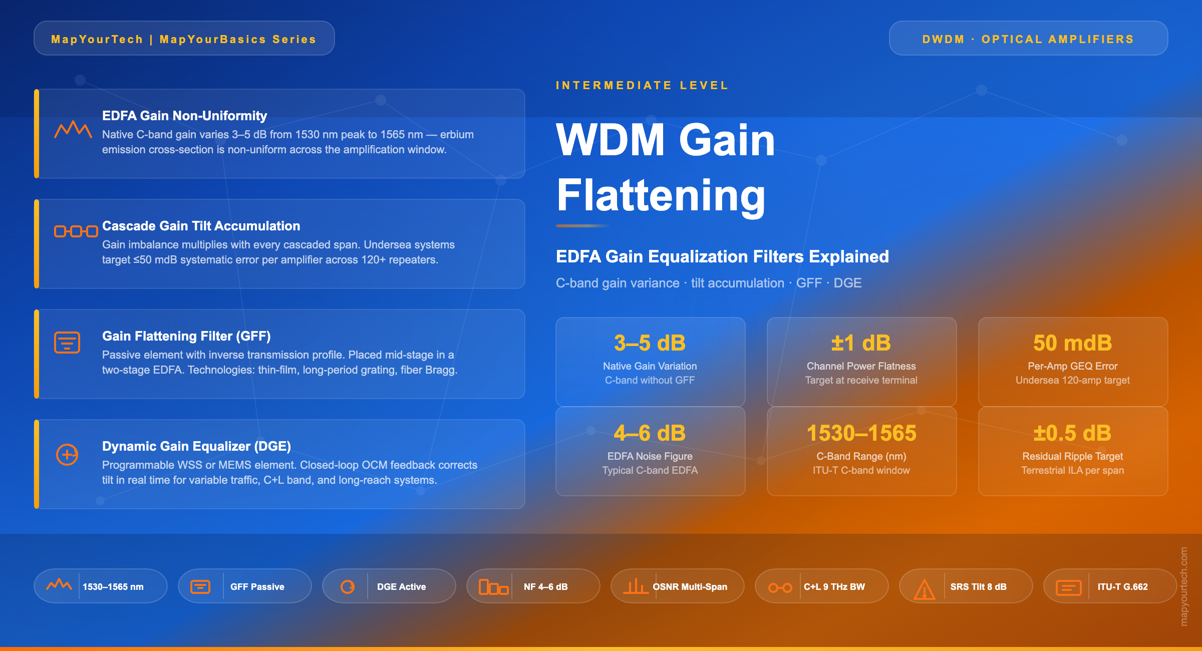
WDM Gain Flattening: EDFA Gain Equalization Filters Explained
How EDFA gain varies across the C-band, why gain tilt compounds over multi-span links, and how gain flattening filters and dynamic gain equalizers preserve channel uniformity in DWDM networks.
1. Introduction
Erbium-Doped Fiber Amplifiers (EDFAs) transformed optical networking by making it possible to amplify dozens of wavelength channels simultaneously without converting signals to and from the electrical domain. Yet this elegant solution comes with a physical constraint that network designers must actively manage: an EDFA does not amplify all wavelengths equally.
Across the C-band — roughly 1530 nm to 1565 nm — the gain provided by an erbium-doped fiber varies with wavelength. Left uncorrected, this variation causes different channels in a Dense Wavelength Division Multiplexing (DWDM) system to arrive at the next amplifier with different power levels. When the signal passes through a second amplifier, the existing imbalance is amplified further. After tens or hundreds of spans in a long-haul or submarine link, some channels carry far more power than others. Channels with excess power push the fiber into nonlinear operating regimes, generating interference and distortion. Channels with insufficient power fall toward the noise floor, increasing bit-error rates and eventually causing link failure.
Gain flattening is the practice of correcting this wavelength-dependent gain variation so that every channel in the DWDM comb experiences equivalent amplification. Two principal tools accomplish this: the Gain Flattening Filter (GFF), a passive component integrated inside the EDFA module, and the Dynamic Gain Equalizer (DGE), an active device that adjusts channel power in response to real-time operating conditions. Understanding how each works, when each applies, and what the performance trade-offs are gives engineers the foundation to design DWDM links that remain stable across widely varying traffic loads and environmental conditions.
This article begins with the physics of the EDFA gain profile, explains how gain imbalance grows with each cascaded span, and then covers the design, performance characteristics, and deployment scenarios for both fixed and dynamic equalization approaches.
2. The EDFA Gain Profile: C-Band Non-Uniformity
2.1 Atomic Physics Behind Gain Variation
An EDFA amplifies light through stimulated emission in a silica fiber doped with erbium (Er³⁺) ions. When a pump laser — typically at 980 nm or 1480 nm — excites erbium ions to a higher energy state, incoming photons at signal wavelengths stimulate the release of identical photons, producing gain. The critical point is that the probability of stimulated emission is not constant across wavelengths. It follows the cross-section spectrum of the erbium ion, which has distinct peaks, shoulders, and valleys across the amplification window.
The emission cross-section of erbium in silica glass peaks sharply near 1530 nm and again — to a lesser degree — around 1550 nm, with a valley and reduced activity in the longer-wavelength region approaching 1565 nm. This creates a gain profile that is inherently non-uniform: channels near 1530 nm receive significantly more gain than channels near 1560–1565 nm. The raw gain difference between the peak and the long-wavelength shoulder can reach 3–5 dB in a single amplifier stage without any correction.
2.2 Factors That Modify the Native Gain Shape
Several operating parameters shift the shape of the gain curve beyond the intrinsic erbium cross-section:
Inversion level. The degree to which erbium ions are excited (the inversion fraction) directly affects the gain spectrum shape. At high inversion — achieved with high pump power — the peak near 1530 nm is pronounced. At lower inversion, the gain spectrum shifts and the relative peak moves toward 1550 nm. This means gain flatness achieved at one pump power setting can degrade if pump power changes, for example due to component aging or temperature variation.
Erbium-doped fiber length and concentration. Longer fiber at a given pump power results in lower inversion and a different spectral shape. Designers must match fiber length, erbium concentration, and pump power together to set the desired operating point.
Temperature. The gain spectrum of an EDFA varies with temperature. Modern EDFA modules include thermoelectric coolers to maintain stable operation over a typical range of −5°C to 70°C, but even small thermal shifts alter the detailed gain shape.
Input signal power and saturation. As the EDFA approaches gain saturation — which occurs when total input signal power exceeds the available population inversion — the gain spectrum shape changes. Channels carrying more power suppress the gain experienced by other channels through gain compression, a form of cross-gain modulation.
What This Means in a DWDM System
In a fully loaded 96-channel C-band system with 50 GHz spacing, channels are spread from approximately 1530 nm to 1565 nm. Without gain equalization, the shortest-wavelength channels can receive 3–5 dB more gain per amplifier than the longest-wavelength channels. After a 20-span terrestrial link, this differential compounds, placing channels in very different operating conditions — a problem that cannot be corrected at the receiver alone.
3. Gain Tilt Accumulation in Multi-Span Systems
3.1 The Cascade Effect
A single EDFA with a small gain ripple is manageable. The problem scales badly when many amplifiers are cascaded in a long-haul link. Consider a system where each EDFA introduces a gain variation of Δg(λ) dB between the strongest and weakest channel. After N spans, the accumulated power differential between the best-case and worst-case channel is roughly N × Δg(λ), assuming no correction between spans. In practice, the situation is more complex because gain variation is spectrally structured rather than a simple linear tilt, but the principle holds: the imbalance multiplies with every span.
In a transoceanic submarine system spanning 7,000–10,000 km with repeater spacing of 50–75 km, the amplifier count can reach 100–200 units. A gain equalization error of only 50 millidB (0.05 dB) per amplifier can accumulate to a 5–10 dB channel power differential over the full link. This is why undersea system designers set extraordinarily tight targets for the systematic gain equalization error of each individual EDFA — historically around 50 mdB per amplifier stage across a 120-amplifier system.
3.2 Gain Tilt vs. Gain Ripple
It helps to distinguish two types of spectral non-uniformity:
Gain tilt refers to a systematic linear slope across the band — channels at one edge of the spectrum consistently receive more (or less) gain than channels at the other edge. Tilt is often caused by the native erbium emission spectrum shape or by spectrally asymmetric stimulated Raman scattering (SRS) in wide-band systems. In C+L band configurations, SRS transfers power from C-band channels (shorter wavelengths) to L-band channels (longer wavelengths), creating a tilt that can reach up to 8 dB per span.
Gain ripple refers to faster spectral oscillations superimposed on any broader slope — peaks and valleys that repeat across the band on wavelength scales of a few nanometers. Ripple arises from the detailed structure of the erbium emission cross-section, from etalon effects in the amplifier module, and from imperfections in the GFF itself. Ripple is harder to correct than tilt because it requires finer spectral resolution in the equalizing element.
3.3 Quantifying the OSNR Impact
Gain non-uniformity degrades system performance through two coupled mechanisms. First, channels with excess power drive the fiber into a nonlinear operating regime, generating self-phase modulation (SPM), cross-phase modulation (XPM), and four-wave mixing (FWM) products that add noise to adjacent channels. Second, channels with insufficient power accumulate a larger fraction of Amplified Spontaneous Emission (ASE) noise relative to signal power, degrading their Optical Signal-to-Noise Ratio (OSNR).
For an N-span system, the OSNR at the receiver for channel i can be approximated as:
/* OSNR at receiver for a single channel in a multi-span system */

OSNRi = Plaunch,i - NFeff - α · Lspan - 10 log(N) - 10 log(hν · Bref)

Where:
  Plaunch,i  = per-channel launch power (dBm)
  NFeff    = effective amplifier noise figure (dB), typically 4–6 dB for EDFA
  α         = fiber attenuation coefficient (dB/km), ~0.2 dB/km at 1550 nm
  Lspan     = span length (km)
  N         = number of spans
  h         = Planck's constant (6.626 × 10⁻³⁴ J·s)
  ν         = optical frequency (Hz)
  Bref      = reference bandwidth (Hz), typically 12.5 GHz for 0.1 nm noise BW

/* If gain is unequal, channel i receives different effective P_launch */
/* Channels near 1530 nm arrive with higher power → nonlinear penalty   */
/* Channels near 1565 nm arrive with lower power → OSNR penalty         */
The practical consequence: to maintain all channels above a minimum OSNR threshold (for example, 20 dB for 100G DP-QPSK), every channel must be kept within a narrow launch power range. Gain equalization is the primary mechanism for achieving this uniformity over a long, amplified link.
Practical Example: 400 km Terrestrial Link
Consider a 400 km link with five 80 km spans, EDFA noise figure of 5 dB, and fiber attenuation of 0.2 dB/km. Without gain equalization, channel power variance after five spans could reach 4–6 dB across the loaded spectrum. With a well-designed GFF holding gain variation to ±0.5 dB per span, the cumulative power variance reduces to ±2.5 dB over the full link — within the operating margin for coherent transceivers using forward-error correction.
4. Gain Flattening Filters (GFF)
4.1 Operating Principle
A Gain Flattening Filter is a passive optical element with a wavelength-dependent transmission profile that is the inverse of the EDFA gain spectrum. Where the EDFA has high gain, the GFF attenuates; where the EDFA has low gain, the GFF passes most of the signal. The combined response of the EDFA gain curve and the GFF transmission yields a flat composite gain across the band.
The GFF is typically placed at the output of the erbium-doped fiber, before the final isolator. This placement ensures that the filter attenuates both amplified signal and any ASE generated by the EDFA, preserving the spectral flatness delivered to the next span. Placing the filter at the input of a second-stage EDFA in a two-stage amplifier design offers an additional benefit: ASE produced in the first stage is filtered before entering the second stage, reducing the amount of ASE that the second stage amplifies.
4.2 GFF Technologies
Several optical technologies have been used to implement gain flattening filters, each with different trade-offs in spectral resolution, insertion loss, and manufacturability.
Thin-film dielectric filters are the most widely deployed technology. Multiple thin-film layers deposited on a glass substrate create a filter with a custom wavelength-dependent transmission profile. By controlling the number, thickness, and refractive index of layers, manufacturers can achieve the detailed spectral shape needed to invert the EDFA gain curve. Thin-film GFFs offer low insertion loss (typically 1–3 dB including the gain penalty from correction), high reliability, and proven long-term stability. Their main limitation is that the spectral profile is fixed at manufacture.
Long-period fiber gratings (LPGs) use a periodic refractive-index modulation in the fiber with a period on the order of hundreds of micrometers. This couples light between the guided core mode and lossy cladding modes at specific wavelengths determined by the grating period. LPGs produce broad, smooth attenuation bands well suited to correcting the coarse shape of the EDFA gain curve. They can be concatenated to produce more complex filter shapes. Insertion loss is low when the grating is formed directly in the transmission fiber.
Short-period fiber Bragg gratings (FBGs) used in reflection mode, combined with circulators, can create very precise attenuation notches. FBG-based equalizers are more complex to implement but offer fine spectral control. They are less common in production GFF applications but appear in laboratory demonstrations and specialized modules.
Acousto-optic tunable filters (AOTFs) use the interaction of light with sound waves in a birefringent crystal to create a tunable narrow-band filter. AOTFs can be made programmable by varying the acoustic frequency and power, giving them dynamic capability — which bridges the gap between fixed GFFs and full dynamic gain equalizers discussed in Section 5.
4.3 Practical Limits of Passive GFFs
A passive GFF is designed to match the EDFA gain profile at a specific operating point: a particular pump power, inversion level, and input signal power. When any of these parameters drift — due to component aging, temperature variation, partial loading of channels, or pump power control errors — the residual gain ripple increases. The GFF cannot respond because it has no active control.
This limitation defines the use case for dynamic gain equalizers: systems where operating conditions vary significantly over time, where the channel count changes (traffic-adaptive loading), or where the required residual flatness tolerance is tighter than a fixed GFF alone can achieve.
5. Dynamic Gain Equalizers (DGE)
5.1 What a DGE Does Differently
A Dynamic Gain Equalizer performs the same spectral shaping function as a GFF, but does so with a programmable attenuation profile that can be updated in real time. The DGE receives a target flatness profile — typically derived from optical channel monitoring measurements — and adjusts the per-wavelength attenuation to drive the output spectrum toward the desired uniformity. This closed-loop capability allows the system to compensate for changes in EDFA operating point, traffic loading, and accumulated tilt from SRS or other sources.
5.2 DGE Technologies
The two principal DGE technologies used in deployed optical networks are Wavelength Selective Switches (WSS) and Micro-Electromechanical Systems (MEMS) arrays.
WSS-based DGEs use liquid crystal on silicon (LCoS) or other beam steering technologies to independently control the attenuation of individual ITU-T grid channels or groups of channels. WSS elements originally designed for ROADM add/drop functions have been adapted for use as dynamic gain equalizers within inline amplifier modules. As LCoS resolution has improved, WSS modules have advanced from single C-band operation to twin-band and integrated C+L configurations. This same resolution improvement enables WSS modules to perform dynamic gain equalization across multiple fiber pairs — quad-WSS modules supporting two C+L fiber pairs are approaching commercial availability, with octal modules (four fiber pairs) technically feasible. The spectral resolution of a WSS-based DGE approaches the channel spacing of the WDM grid, allowing per-channel power control.
MEMS-based DGEs use arrays of tiny tilting mirrors, one per wavelength channel or per small spectral band, to vary the coupling efficiency into an output fiber. By applying voltage to individual mirror elements, the controller can independently set the attenuation of each spectral band. MEMS DGEs typically offer fast response times and high reliability, but are more complex to manufacture at very fine spectral resolution compared to LCoS-based WSS elements.
5.3 Control Architecture
A DGE in a deployed system operates within a control loop that includes optical channel monitoring (OCM) to measure the current spectral power profile, a controller that computes the required per-channel attenuation corrections, and the DGE element itself that applies those corrections. The loop runs continuously, updating the attenuation profile as operating conditions change.
The control target is typically a flat output power spectral density — all channels at a common power level after the DGE. In C+L band systems, where SRS creates a wavelength-dependent power tilt that varies with traffic loading, the DGE target profile may include a pre-calculated tilt correction that compensates for the expected SRS contribution for the current number of loaded channels.
Passive GFF
Fixed spectral profile set at manufacture. Low insertion loss. No electrical power required. Corrects the static EDFA gain shape. Cannot adapt to changing operating conditions or partial loading.
Dynamic Gain Equalizer (DGE)
Programmable attenuation profile updated in real time. Adapts to traffic changes, temperature drift, and component aging. Higher complexity and cost than passive GFF. Typically combined with OCM monitoring.
Combined Approach
Practical high-performance amplifiers use a passive GFF to handle the bulk of the static gain correction, with a DGE for fine dynamic trimming. The GFF reduces the dynamic range that the DGE must accommodate, simplifying the DGE design.
6. Performance Metrics and Design Trade-offs
6.1 Key Performance Metrics
Several metrics characterize the effectiveness of a gain equalization scheme in a deployed DWDM system.
Residual gain ripple is the peak-to-peak variation in gain across the amplified band after all equalization is applied. A residual ripple of ±0.5 dB per span is a common design target for terrestrial long-haul systems. Undersea systems require tighter values — systematic gain equalization errors must be held within approximately 50 mdB per amplifier to prevent unacceptable channel power differentials over a system with 120 or more amplifiers.
Channel power flatness is measured at the system level, after all amplifier spans, and represents the peak-to-peak power variation across the loaded WDM spectrum at the receiver. A target of ±1 dB channel power flatness at the receive terminal is typical for high-performance terrestrial systems.
Insertion loss of the GFF is a direct noise penalty. Every decibel of GFF insertion loss is a decibel of signal power removed before the second amplifier stage restores it, which worsens the mid-stage noise figure contribution. Designers minimize GFF insertion loss by choosing a design that corrects only what is necessary — targeting the minimum attenuation profile that achieves the required flatness.
Dynamic range of the DGE defines the maximum per-channel attenuation that the equalizer can apply. Wider dynamic range allows the DGE to handle larger input power differentials, but generally increases insertion loss in the low-attenuation state. Typical DGE dynamic range is 10–20 dB of per-channel attenuation.
6.2 Noise Figure Penalty from Mid-Stage Loss
In a two-stage EDFA with a mid-stage element (GFF, dispersion compensating module, or DGE), the overall noise figure is governed by the Friis cascaded noise figure formula:
/* Cascaded noise figure for two-stage EDFA with mid-stage loss */

NFtotal = NF1 + (Lmid × NF2 - 1) / G1   (linear values)

In dB (approximate):
NFtotal,dB ≈ NF1,dB + Lmid,dB + NF2,dB - G1,dB   (only when G₁ >> 1)

Where:
  NF1       = noise figure of Stage 1 (linear)
  NF2       = noise figure of Stage 2 (linear)
  Lmid      = mid-stage insertion loss (linear, ≥ 1)
  G1        = gain of Stage 1 (linear)

Practical Example:
  Stage 1 gain G₁ = 15 dB → 31.6×
  Stage 1 NF₁ = 4 dB
  Mid-stage GFF loss = 2 dB → 1.585×
  Stage 2 NF₂ = 5 dB
  → NF_total ≈ 4 + 2 + 5 - 15 ≈ -4 dB correction term applies
  → Dominant term is NF₁ ≈ 4 dB (Stage 2 noise contribution ~0.3 dB)
  ✓ High Stage 1 gain suppresses the noise contribution of mid-stage loss
The Friis relationship shows why Stage 1 gain matters so much. If Stage 1 provides 15–20 dB of gain before the mid-stage GFF, the noise contribution of the GFF insertion loss is divided by the Stage 1 gain factor — reducing it to a fraction of a decibel. This is why two-stage amplifier designs with a high-gain first stage approach the noise performance of an ideal single-stage amplifier despite the additional loss element between stages.
Design Rule
To minimize the noise penalty of a mid-stage GFF, maximize Stage 1 gain. A Stage 1 gain of 15–20 dB reduces the effective noise contribution of 2–3 dB of mid-stage loss to less than 0.1–0.2 dB of overall NF degradation. Conversely, placing a high-loss element (e.g., a dispersion compensating module) in the mid-stage without adequate Stage 1 gain significantly degrades the cascaded noise figure.
6.3 Gain Equalization in C+L Band Systems
In C+L band configurations, gain equalization becomes substantially more complex. The two amplification bands — C-band (1530–1565 nm, approximately 4.5 THz) and L-band (1565–1625 nm, approximately 4.5 THz) — are handled by separate EDFA chains that are later recombined. Each band requires its own GFF or DGE, designed for the specific gain shape of its EDFA type. The L-band EDFA is operated at lower inversion than the C-band EDFA, producing a different spectral gain shape that requires a separately optimized filter.
Additionally, SRS-induced power tilt between the C- and L-band becomes a significant equalization challenge. Power transferred from C-band to L-band channels can reach approximately 8 dB per 100 km span, requiring tilt correction in each amplifier stage. DGEs or tilt-control elements in the amplifier chain must track this SRS contribution dynamically, particularly when traffic channels are added or removed and the aggregate launched power changes.
As of 2026, integrated C+L WSS modules are commercially available, enabling combined dynamic gain equalization across both bands in a single module. This reduces the component count in the amplifier node compared to separate C-band and L-band DGE elements.
7. Practical Deployment Considerations
7.1 Amplifier Position and Equalization Strategy
The role of gain equalization depends on where in the network the amplifier sits. Three primary positions define different requirements:
Table 1: Practical Example — Gain Equalization Requirements by Amplifier Position
| Position | Role | Key GEQ Requirement | Typical Technology |
|---|---|---|---|
| Booster (post-TX) | Increase launch power from transmitter | Channel power pre-emphasis before first span; flatness not as tight as inline | Passive GFF, VOA per channel |
| Inline (ILA) | Restore span loss at regular intervals | Tight per-span flatness; systematic error must not compound over many spans | GFF + optional DGE; two-stage design |
| Pre-amplifier (pre-RX) | Boost weak signal before coherent receiver | Low noise figure is paramount; flatness matters for multi-channel demux | Low-NF first stage, GFF at output |
7.2 Partial Loading and Traffic-Adaptive Gain
A frequently encountered operational challenge is that DWDM systems are rarely fully loaded from day one. As capacity is added incrementally, the total input power to each EDFA changes, shifting its operating point and altering the gain spectrum shape. A GFF designed and optimized for the fully loaded condition may perform less well when only a fraction of channels are active.
Two strategies address partial loading. The first is automatic gain control (AGC), where the pump power is adjusted to maintain a constant gain per channel regardless of how many channels are present. AGC prevents the EDFA from drifting to a different inversion level as loading changes, which would shift the gain spectrum shape away from the GFF design point. The second strategy is to use a DGE that actively measures the output spectrum and corrects for any residual non-uniformity introduced by the changed operating point.
7.3 GFF Characterization and Qualification
For high-performance applications, particularly undersea systems, GFF units undergo rigorous spectral characterization. The filter is measured at multiple temperatures across the operating range, at multiple input power levels, and at different total signal bandwidths. The measured gain-plus-filter composite response must fall within a defined tolerance mask across the entire amplification band. A systematic error in this characterization — even one that is small per amplifier — accumulates to a meaningful channel power differential over a 120-amplifier link, which is why the 50 mdB per-amplifier target is specified for such systems.
Operational Note: Gain Tilt Under Fault Conditions
When a fiber cut or node failure removes some wavelength channels from the system, the remaining channels experience changed operating conditions in every downstream EDFA. The total input power drops, the inversion level shifts, and the gain shape changes relative to the GFF design point. In systems without DGE, this can cause surviving channels to experience gain transients. Modern amplifier controllers include transient suppression algorithms that quickly adjust pump power to minimize the gain excursion when channel count changes suddenly. DGE-equipped systems can also apply active spectral corrections within milliseconds to restore flatness.
7.4 Summary Comparison: GFF vs. DGE
Table 2: GFF vs. Dynamic Gain Equalizer — Design and Operational Comparison
| Parameter | Passive GFF | Dynamic Gain Equalizer (DGE) |
|---|---|---|
| Attenuation profile | Fixed at manufacture | Programmable in real time |
| Spectral resolution | Continuous (full spectrum) | Per ITU-T channel or small band groups |
| Insertion loss | 1–3 dB typical | 3–7 dB typical (higher dynamic range designs) |
| Adaptability | None — static correction only | Full — responds to loading, temperature, aging |
| Residual ripple | ±0.5 dB achievable at design point | <±0.3 dB with closed-loop control |
| Cost | Low (passive element) | Higher (active electronics, OCM feedback) |
| Typical application | Terrestrial ILA, fixed-load systems | Flexible load systems, C+L band, submarine |
| Control requirement | None | OCM monitoring + control processor |
Section Summary: Gain Equalization in Practice
- EDFA gain is inherently non-uniform across the C-band, with raw gain variation of 3–5 dB between the 1530 nm peak and the 1560–1565 nm region.
- In multi-span systems, this variation compounds with every amplifier, requiring active correction to keep all channels within a usable power and OSNR range.
- A passive GFF corrects the static gain shape at a specific operating point with low insertion loss and no active electronics.
- A DGE provides real-time, programmable spectral control, essential for systems with variable loading, wide bandwidth (C+L), or very long reach.
- Two-stage EDFA designs with high Stage 1 gain suppress the noise contribution of mid-stage GFF or DGE insertion loss to a fraction of a decibel.
8. Future Directions
The demand for wider optical bandwidth — pushing beyond the C-band into L-band, S-band, and eventually extended C+L configurations — makes gain equalization more complex and more important. As the amplified spectrum widens from approximately 4.5 THz for the C-band to 9 THz for C+L and potentially beyond, the spectral non-uniformity that must be corrected grows in both magnitude and structure. A passive GFF designed for a 38 nm C-band application cannot simply be extended to a 77 nm C+L application; the underlying EDFA physics in the two bands differ fundamentally.
Improvements in LCoS-based WSS technology are enabling integrated C+L DGE modules in a single physical unit, reducing node complexity for wide-band amplifier designs. As LCoS spatial resolution improves, the same module that performs ROADM switching can also provide dynamic gain equalization without requiring a separate component. Quad-WSS modules supporting dynamic gain equalization across two C+L fiber pairs simultaneously are approaching the market, with further integration expected.
On the algorithmic side, machine learning methods are being explored to predict optimal DGE setpoints based on traffic load, temperature, component aging state, and historical performance data. These model-based control approaches can anticipate gain shape changes before they manifest as channel power errors, rather than waiting for the closed-loop OCM feedback to detect and correct them.
The fundamental physics of erbium amplification will not change — the C-band gain non-uniformity is a property of the erbium ion in silica glass. But the tools for managing it are becoming more capable, more integrated, and more intelligent, enabling higher-capacity systems to operate reliably across wider bandwidths and longer distances.
Glossary
AGC — Automatic Gain Control
A pump power control mechanism that adjusts EDFA pump power to maintain a constant gain per channel as the number of loaded channels changes.
ASE — Amplified Spontaneous Emission
Broadband optical noise generated when excited erbium ions spontaneously emit photons that are amplified along with the signal. The primary noise source in EDFA-based systems.
DGE — Dynamic Gain Equalizer
An active optical element with a programmable wavelength-dependent attenuation profile, used to maintain channel power uniformity as operating conditions change.
DWDM — Dense Wavelength Division Multiplexing
A transmission technique that carries multiple optical channels on a single fiber, each at a different wavelength spaced according to the ITU-T frequency grid.
EDFA — Erbium-Doped Fiber Amplifier
An optical amplifier based on stimulated emission in silica fiber doped with erbium ions, pumped at 980 nm or 1480 nm. Amplifies signals in the C-band (1530–1565 nm) and L-band (1565–1625 nm).
Gain Ripple
Fine spectral oscillations in the EDFA gain profile, distinct from the coarser gain tilt. Ripple results from the detailed structure of the erbium emission cross-section and from etalon effects inside the module.
Gain Tilt
A systematic slope in EDFA gain across the amplification band, where channels at one wavelength edge receive consistently more or less gain than channels at the other edge.
GFF — Gain Flattening Filter
A passive optical element with a wavelength-dependent transmission profile that is the inverse of the EDFA gain spectrum, used to produce a flat composite gain across the amplification band.
LPG — Long-Period Fiber Grating
A periodic refractive-index modulation in fiber with period on the order of hundreds of micrometers, used to couple core-guided light to lossy cladding modes at specific wavelengths for GFF applications.
OCM — Optical Channel Monitor
A device that measures the power of individual wavelength channels in a DWDM system, providing feedback data for DGE control loops and network management systems.
OSNR — Optical Signal-to-Noise Ratio
The ratio of signal power to ASE noise power in a defined reference bandwidth, typically 0.1 nm. OSNR is the primary indicator of signal quality in optically amplified DWDM systems.
WSS — Wavelength Selective Switch
A programmable optical element that independently routes or attenuates individual wavelength channels, used in ROADMs for add/drop functions and in amplifier modules as dynamic gain equalizers.
References
- ITU-T G.662 — Generic characteristics of optical amplifier devices and subsystems, ITU-T Study Group 15.
- ITU-T G.694.1 — Spectral grids for WDM applications: DWDM frequency grid, ITU-T Study Group 15.
- A. Saleh and J. Hecht, "Optical amplifiers: Status and future directions," IEEE Journal of Lightwave Technology.
- E. Desurvire, "Erbium-Doped Fiber Amplifiers: Principles and Applications," Wiley-Interscience.
- P. Poggiolini et al., "The GN-model of fiber non-linear propagation and its applications," Journal of Lightwave Technology.
- J.-X. Cai et al., "49.3 Tb/s transmission over 9100 km using C+L EDFA," Journal of Lightwave Technology.
- OIF Implementation Agreement IA-DWDM-EQP-100G — Optical Internetworking Forum.
Developed by MapYourTech Team
For educational purposes in Optical Networking Communications Technologies
Note: This guide is based on industry standards, best practices, and real-world implementation experiences. Specific implementations may vary based on equipment vendors, network topology, and regulatory requirements. Always consult with qualified network engineers and follow vendor documentation for actual deployments.
Feedback Welcome: If you have suggestions, corrections, or improvements to propose, please write to us at [email protected]

Optical Communications & Network Automation Expert | Author of 3 Books for Optical Engineers | Founder, MapYourTech
Optical networking engineer with nearly two decades of experience across DWDM, OTN, coherent optics, submarine systems, and cloud infrastructure. Founder of MapYourTech. Read full bio →
Follow on LinkedIn