The Power-Per-Bit Case for Router Optics
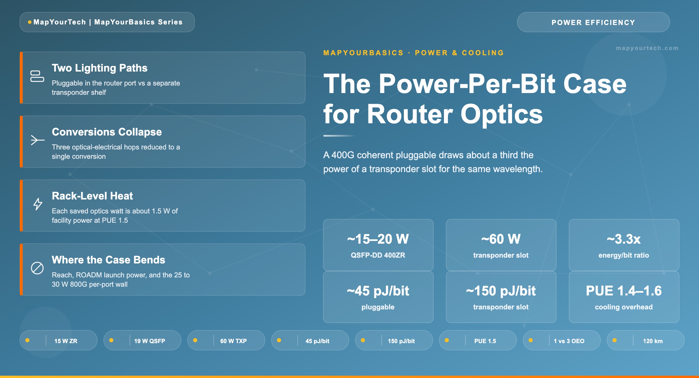
A 400G coherent pluggable in a router port draws roughly a third of the power a separate transponder slot needs to carry the same wavelength. This article turns the per-module figure into rack-level power and cooling math an engineer can defend in a design review.
1. Introduction
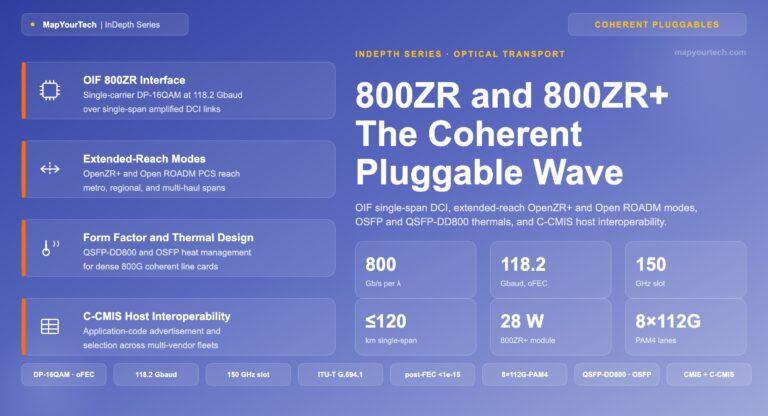
A 400G coherent pluggable in a QSFP-DD form factor dissipates 15 to 20 W; the OIF set the original 400ZR target at 15 W, and shipping modules land near 19 W. A 400G wavelength carried on a conventional transponder slot — the coherent module plus its host line card and framing electronics — runs closer to 60 W for the same 400 Gb/s of line capacity. That difference is the entire economic argument for IP-over-DWDM (IPoDWDM): collapse the transport conversion stage into the router port and you stop paying its power bill.
The per-module number is the easy part. Translating it into something a facilities team can act on — rack heat load, cooling overhead, breaker sizing — takes one multiplication step that engineers routinely skip. Every watt a transceiver burns becomes heat that the air handlers must remove, and that removal itself draws additional power. A 40 W saving per port is not a 40 W saving at the meter; at a Power Usage Effectiveness (PUE) of 1.5 it is closer to 60 W.
This article works through the comparison at three levels: the module, the line card, and the rack. It defines the energy-per-bit metric that lets you compare modules of different rates on equal terms, shows the rack-level cooling math with realistic port counts, and marks the boundary conditions where the pluggable advantage shrinks — long-haul reach, ROADM launch power, and the 800G thermal wall that is already reshaping the choice.
2. Two Ways to Light a Wavelength
A coherent DWDM wavelength needs the same functional blocks regardless of where they physically sit: a tunable laser, a coherent modulator and receiver front end, a digital signal processor (DSP) that handles chromatic dispersion, polarization-mode dispersion, and forward error correction (FEC), and a host that frames client traffic onto the line. The two architectures differ only in how those blocks are packaged and how many times the signal is converted between optical and electrical form.
2.1 The transponder path
In the conventional model the router speaks short-reach grey optics — a 400G-DR4 or FR4 client module at roughly 10 to 12 W — into a separate optical shelf. Inside that shelf a transponder or muxponder card terminates the client signal, reframes it (often in Optical Transport Network, or OTN, framing), and re-modulates it onto a coherent line wavelength using either an embedded coherent engine or a CFP2-DCO module. The CFP2-DCO module itself draws 12 to 28 W depending on baud rate and reach. The slot it sits in adds the host ASIC, the framer, the OTN overhead processing, and power-supply conversion losses, which is why the all-in figure per 400G transponder port lands near 60 W rather than the module's own 20-odd watts.
The signal therefore crosses the optical-electrical boundary three times between the router and the fiber: grey optic out of the router, electrical termination in the transponder, coherent optic onto the line. Each conversion has a power cost, and the grey client link is pure overhead that exists only to bridge two boxes. Understanding why coherent detection dominates this layer at all is covered in the MapYourTech guide on coherent versus direct-detect transceiver selection.
2.2 The pluggable path
IPoDWDM removes the shelf. A 400ZR or OpenZR+ pluggable in QSFP-DD or OSFP form factor goes straight into the router line card and presents both the client function and the coherent line interface in one module. The router NPU handles framing; the module's 7 nm DSP handles fiber impairments. The grey client link disappears, one whole network element disappears, and the optical-electrical conversion count drops from three to one. The architecture and its trade-offs are laid out in the MapYourTech primer on the basics of IP over DWDM.
The same physics now lives in a 15-to-20 W envelope instead of a 60 W slot because the pluggable carries no separate client optic, no OTN framer, and no chassis-level power conversion of its own — it borrows the router's. The penalty is a tighter power and thermal budget: the OIF deliberately constrained 400ZR to the minimum feature set needed for the data-center-interconnect (DCI) use case so it would fit a router cage, which is also why early 400ZR launches at −10 dBm and needs amplification on most links. The interaction between launch power and reach is examined in the MapYourTech analysis of 0 dBm coherent transceivers.
3. From Per-Module Watts to Rack-Level Heat
Comparing a 15 W module to a 60 W slot is fair only when both carry the same line rate. The metric that normalizes across rates and form factors is energy per bit, expressed in picojoules per bit (pJ/bit). It divides electrical power by throughput, so an 18 W 400G module and a 25 W 800G module can be ranked on the same axis. The full treatment of this metric and green network design lives in the MapYourTech article on pJ/bit metrics and energy-efficient optical networks.
Energy per bit
E_bit = P_module / R_line

Where:
  E_bit     = energy per transported bit   [pJ/bit]
  P_module  = electrical power dissipated   [W = J/s]
  R_line    = line data rate                [Gb/s = 10^9 bit/s]

Unit identity:  1 W / 1 (Gb/s) = 1 nJ/bit = 1000 pJ/bit

QSFP-DD ZR:   18 W / 400 Gb/s = 0.045 nJ/bit = ~45 pJ/bit
Transponder slot: 60 W / 400 Gb/s = 0.150 nJ/bit = ~150 pJ/bit
At the module level the pluggable lands near 45 pJ/bit against roughly 150 pJ/bit for the full transponder slot — a factor of about 3.3 on energy per bit for an identical 400 Gb/s wavelength. That ratio is the lever; everything below is arithmetic applied to it.
3.1 Scaling to the line card and the rack
A modern router line card carrying 36 ports of 400G illustrates the climb. Populate every port with a QSFP-DD ZR module at 18 W and the optics dissipate 648 W. Light the same 36 wavelengths through transponder slots at 60 W each and the optics-plus-transport dissipation is 2,160 W — before counting the rack units the separate shelf occupies, which a router-hosted design reclaims entirely. The gap is roughly 1.5 kW of continuous dissipation per 36-port card.
Heat does not stop at the chassis. Effectively all electrical power a transceiver draws is converted to heat the facility must remove, and removing it costs more power. PUE is the multiplier: a conventional air-cooled hall runs PUE 1.4 to 1.6, meaning every watt of IT load pulls another 0.4 to 0.6 W of cooling and facility overhead. The rack-level power a facilities team must provision is therefore the IT dissipation scaled by PUE.
Facility power for an optics population
P_facility = N_ports × P_port × PUE

Where:
  N_ports  = number of 400G ports
  P_port   = per-port dissipation        [W]
  PUE      = Power Usage Effectiveness   [~1.5 air-cooled]

Pluggable, 36 ports:   36 × 18 W × 1.5 = ~972 W
Transponder, 36 ports: 36 × 60 W × 1.5 = ~3,240 W
Facility-level delta: 3,240 − 972 = ~2,268 W per cardAn operator fills a rack with four 36-port 400G router line cards, lighting 144 wavelengths. With QSFP-DD ZR pluggables the optics draw 144 × 18 W = 2,592 W; at PUE 1.5 the facility provisions about 3,888 W for those optics. The transponder-based equivalent draws 144 × 60 W = 8,640 W of IT load, or about 12,960 W at the meter. The pluggable design saves roughly 9 kW of provisioned facility power on this single rack — close to a full standard rack's worth of budget — and frees the rack units the transponder shelves would have consumed. At a representative U.S. industrial rate near 14 cents per kWh, 9 kW of continuous draw is on the order of 11,000 USD per year in energy alone, before counting the cooling plant capital it avoids.
One published operator measurement anchors the order of magnitude: Colt reported a 33% reduction in power per bit after moving to pluggable optics, and a Juniper converged-architecture study cited a 54% power reduction alongside a 77% space reduction at the system level. The module-level ratio is steep; the realized network savings are smaller because the line system, amplifiers, and router host do not shrink — only the transport conversion stage does.
| Parameter | QSFP-DD 400ZR pluggable | 400G transponder slot |
|---|---|---|
| Coherent engine power | ~15–20 W (module total) | ~12–28 W (CFP2-DCO only) |
| Grey client optic | None — integrated | ~10–12 W (separate) |
| Host card + framing overhead | Borrows router host | Adds to slot total |
| All-in per-400G power | ~15–20 W | ~60 W |
| Energy per bit | ~45 pJ/bit | ~150 pJ/bit |
| Optical-electrical conversions | 1 | 3 |
| Separate rack space | None | Transponder shelf |
Engineering note. The 60 W comparison point is a transponder slot, not a CFP2-DCO module. The module alone is 12 to 28 W; the slot reaches ~60 W once the grey client optic, OTN framer, host ASIC, and power-conversion losses are counted. Quoting "60 W CFP2-DCO" against "18 W QSFP-DD" compares a system to a component and overstates the module-to-module gap. Compare module-to-module (roughly 18 W versus 20 to 28 W) or slot-to-slot (roughly 20 W versus 60 W), but never one of each.
3.2 Interactive: Test the Rack-Level Math
The calculator below applies the same two formulas to inputs you control. Move the port count, per-port power, PUE, and energy price; the bars and figures update live. The lighter band stacked on each bar is the cooling overhead the facility must remove on top of the optics dissipation, scaled by PUE. The presets load a single 36-port card, a 144-port rack, and a 288-port hyperscale row.
4. Where the Argument Holds and Where It Bends
The power-per-bit case is strongest exactly where 400ZR was designed to win: point-to-point DCI and metro links up to about 120 km, amplified, with a router that has the cage power class to host coherent optics. In that envelope the pluggable removes a shelf, a grey link, and two optical-electrical conversions, and the rack math above applies directly.
Reach is the first boundary. 400ZR targets roughly 80 to 120 km amplified; OpenZR+ pushes to regional distances, but ultra-long-haul and submarine routes still favor embedded transponders that are not bound by a pluggable's power envelope and can run higher-baud, higher-performance DSPs. The reach class drives the architecture, not the other way around — a point developed in the MapYourTech overview of C+L band DWDM systems for capacity-limited backbone routes.
Launch power is the second. Many 400ZR modules emit −10 dBm, which limits their use through high-degree ROADMs without amplification; 0 dBm and "Bright" variants with an embedded mini-EDFA close that gap at the cost of a little more module power. Where an operator needs OTN overhead, hard protection switching, or a clean optical demarcation between the IP and transport teams, a pluggable transponder — a dedicated chassis hosting MSA pluggables — carries roughly 25 to 50% more cost than direct router hosting but restores those transport features. The disaggregated line-system context for both choices is covered in the MapYourTech piece on open line systems for multi-vendor coherent wavelengths.
The third boundary is the one bending the curve now. The 800G generation in OSFP draws 25 to 30 W per module, which exceeds the ~18 W per-port limit some back-end GPU fabric switches impose. Above that line, operators either accept architectural workarounds or fall back to intermediate pluggable transponders — the same thermal ceiling that made 400ZR a router-port fit is now pushing 800ZR back out of some router cages. The next-generation interface roadmap, including 800ZR adoption and the move toward 1.6T, is tracked in the MapYourTech guide to 800G ZR/ZR+ coherent optics.
5. Summary
The per-module figure is the headline, but the rack-level multiplication is what makes the case actionable. Carry the comparison through PUE and a realistic port count and the saving lands where budgets are set: provisioned facility power and rack space.
Takeaway: A 400G QSFP-DD ZR pluggable dissipates 15 to 20 W and lands near 45 pJ/bit; a 400G transponder slot — module plus host card and framing — runs about 60 W and roughly 150 pJ/bit, a factor near 3.3 on energy per bit for the same wavelength. The CFP2-DCO module alone is only 12 to 28 W, so always compare module-to-module or slot-to-slot, never a component against a system. At PUE 1.5 every saved watt of optics is about 1.5 W of provisioned facility power, so a 36-port 400G card saves on the order of 2.3 kW at the facility level and a four-card rack saves roughly 9 kW — near a full rack's budget. The advantage holds for amplified DCI and metro links up to about 120 km and bends at long-haul reach, ROADM launch-power limits, and the 25 to 30 W per-port wall that 800G OSFP modules are now hitting in router cages.
References
- Optical Internetworking Forum (OIF), Implementation Agreement OIF-400ZR — 400ZR.
- OpenZR+ Multi-Source Agreement, "Multi-Vendor 400G Coherent Optical Transceiver" white paper, openzrplus.org.
- U.S. Department of Energy, data center Power Usage Effectiveness (PUE) efficiency metrics.
- Sanjay Yadav, "Optical Network Communications: An Engineer's Perspective" — Bridge the Gap Between Theory and Practice in Optical Networking.