
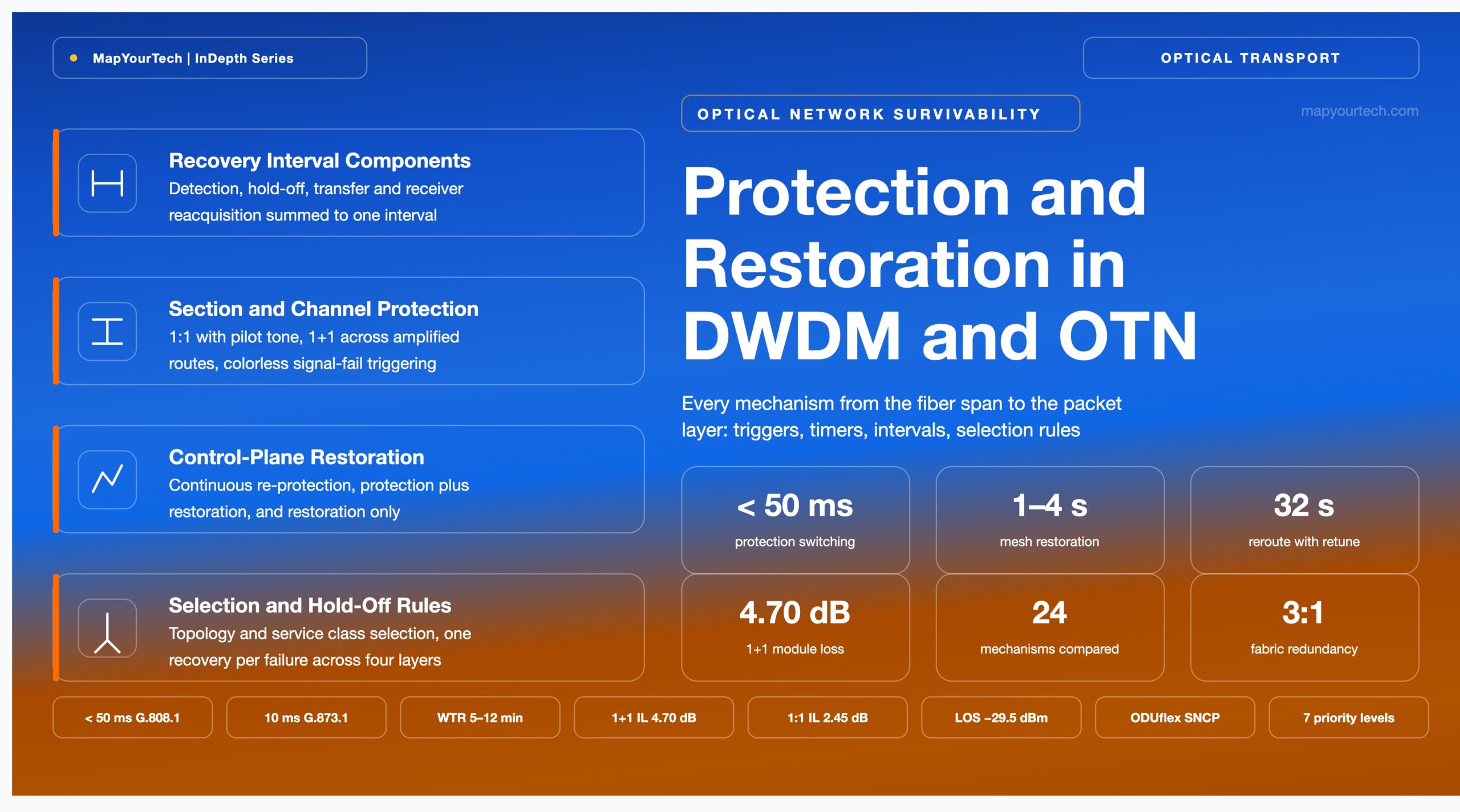
Protection and Restoration Mechanisms in DWDM and OTN Networks: Complete Comparison and Selection Guide
Every recovery mechanism from the fiber span to the packet layer, with its switching trigger, timer behaviour, insertion-loss cost, recovery interval, coverage boundary and application case — and the rules that map a topology and a service class onto one of them.
Comprehensive Guide · Optical Transport Architecture · Advanced
A protection path shares its risk before it shares its traffic.
1. Introduction
A single duct cut removes every wavelength in that cable simultaneously, and the outage the service then records is determined by design decisions taken months earlier: which layer holds the recovery logic, whether the spare capacity was dedicated or shared, and how long each layer was told to wait before acting. A dedicated optical selector returns traffic in tens of milliseconds and consumes a second full path to do it. A control-plane reroute onto shared capacity consumes almost nothing until the failure and returns traffic seconds to tens of seconds later, if a feasible route exists at that moment. Each is correct for a different requirement, and the mechanism set spanning the interval between them runs to more than twenty entries on a modern transport platform.
This guide covers every recovery mechanism available in a modern DWDM and Optical Transport Network (OTN) platform: fiber-span and optical multiplex section protection, optical channel and client-port protection, subnetwork connection protection at the Optical Data Unit (ODU) layer, route switching through ROADM degrees, the control-plane restoration classes, packet-layer protection, and the equipment redundancy underneath all of them. Each one is treated the same way — trigger, timer behaviour, recovery interval, capacity cost, coverage boundary, application case — and the closing sections convert that into selection rules, a hold-off ordering discipline, a constraints list and a deployment checklist.
Figures carry their evidence class. Standard-specified means a recommendation fixes the value; vendor implementation means a platform datasheet reports it and other implementations may differ; design practice means the number comes from planning experience. Terminology follows the distinctions between resiliency, redundancy, protection and survivability, and the arithmetic that converts a recovery interval into contracted downtime sits in optical network architecture design for maximum availability.
2. Recovery Interval Definition and Component Terms
The recovery interval is the elapsed time between the physical event that interrupts a service and the moment that service carries traffic again on a different path. It is measured in milliseconds or seconds, it is defined by its two endpoints rather than by any single piece of equipment, and it resolves into four additive terms: defect detection, configured hold-off, switch transfer, and receiver reacquisition.
2.1 Distinctions Between Adjacent Quantities
Protection and restoration differ in when the recovery path is chosen, not in how fast it is. RFC 4427 fixes the distinction on resource allocation: a protection path is computed, signalled and reserved before the failure, while a restoration path is computed or committed after it. Every millisecond-class mechanism in this guide is protection; every second-class mechanism is restoration.
Protection switching time and recovery time are different intervals. Protection switching time covers the selector transfer and any protocol exchange, and ends when the standby path is connected, not when traffic is carried. Recovery time contains it and also contains detection, hold-off and receiver reacquisition. On coherent interfaces the reacquisition term dominates, which is why a switch that meets the 50 ms objective can still show a 60 ms service outage; the scope of that objective across SDH, OTN and packet layers is set out in the 50 ms protection switching reference.
Hold-off time and wait-to-restore time both delay a switch, at opposite ends of the event. Hold-off delays the outgoing switch so that a lower layer gets the first opportunity to recover, and is a configured value rather than a property of any card. Wait-to-restore delays the return to the repaired working path, and ITU-T G.808.1 recommends 5 to 12 minutes for it so that an intermittent fault cannot drive repeated switching (standard-specified).
Defect detection and defect persistency are separate steps. Detection registers the condition; persistency filtering requires it to stay present for a verification interval before the protection controller is told. ITU-T G.873.1 recommends that this interval be no more than 10 ms for ODU protection, and treats the persistency time as part of the combined signal-fail and hold-off term (standard-specified).
2.2 Units and the Interval Arithmetic
Trecovery = Tdetect + Tholdoff + Tswitch + Treacq
Where:
- Trecovery — failure event to traffic carried on the recovery path, in ms (20 ms to 60 s across the mechanisms in this guide)
- Tdetect — loss-of-light or defect detection plus persistency filtering, in ms (5–10 ms typical; verification interval recommended at no more than 10 ms in ITU-T G.873.1)
- Tholdoff — configured delay before the protection controller acts, in ms (0 ms where the layer recovers first; 100–500 ms where a lower layer is given precedence)
- Tswitch — selector or cross-connect transfer plus any protocol exchange, in ms (1–20 ms for an optical switch or an ODU cross-connect; seconds where a control plane computes and signals the path)
- Treacq — receiver reacquisition from signal presence to traffic, in ms (25–60 ms for a coherent receiver with a bounded dispersion search; tens of seconds where the transmitter must retune)
Every term is in the same unit, so no conversion enters the sum. A figure quoted without its two endpoints is not comparable with any other figure.
Applying the arithmetic to the protected optical channel of Figure 1: detection and persistency take 8 ms, hold-off is 0 ms because no lower layer recovers first, the optical selector transfers in 12 ms, and the coherent receiver reacquires in 40 ms. The recovery interval is 8 + 0 + 12 + 40 = 60 ms against a 50 ms switching objective, and the design is compliant because the objective applies to the switching term rather than to the sum. Every "under 50 ms" figure quoted later in this guide is a switching interval on the same basis.
Takeaway: Recovery time contains protection switching time, and the two are routinely quoted as if they were one interval. Fix the endpoints first: detection plus hold-off plus transfer plus reacquisition, in milliseconds, with the mechanism that owns each term named. Quote the switching figure for standards compliance and the full interval for the customer.
3. Mechanism Placement Across the Transport Layer Stack
Each layer of the transport stack detects a subset of failures and can move traffic only within the resources it owns, and those two facts decide which mechanism belongs where. ITU-T G.872 separates the optical transmission section, the optical multiplex section carrying the multiplexed band, and the optical channel carrying one client wavelength; ITU-T G.709 adds the ODU as a monitored electrical container above them; the packet layer sits above that. A fiber cut is visible as loss of light at the section layer, as loss of the optical channel at the transponder, as a signal-fail defect in the ODU overhead, and as a set of simultaneously dead links at the packet layer. Four layers see one event, and four layers can act on it.
Read the Full Analysis with Premium
The remaining 89% of this article — the design numbers, trade-offs and field guidance — is part of MapYourTech Premium, along with the full premium library, courses and professional tools.
You May Also Like
-
Free
-
August 27, 2026
-
Free
-
August 27, 2026
-
Premium
-
August 27, 2026