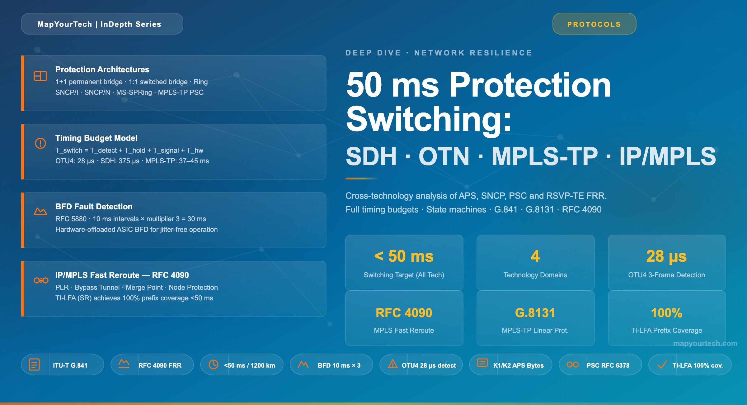
50 ms Protection Switching: SDH, OTN, MPLS-TP, and IP/MPLS
A cross-technology analysis of protection switching architectures — from Automatic Protection Switching in SDH to RSVP-TE Fast Reroute in IP/MPLS — with full timing budget models, state machine comparisons, and design guidance for mission-critical networks.
1. Introduction
Network resilience is not a luxury — it is the contract between a carrier and every service riding its infrastructure. Power utilities, financial trading platforms, mobile backhaul, and broadcast contribution all depend on one shared expectation: when a fiber is severed, a node fails, or a laser dies, the traffic recovers before anyone notices. That expectation is encoded as a 50 millisecond switching time, a figure that has shaped the design of transport protocols for over three decades.
The 50 ms threshold originated in the Synchronous Digital Hierarchy, where it was codified in ITU-T G.841 as the Multiplex Section Protection (MSP) objective. It was chosen because human perception of a voice interruption becomes annoying above roughly 100 ms, and because telephony signaling systems of the 1990s had hold timers calibrated around that threshold. As networks migrated from SDH/SONET to Optical Transport Networks (OTN), and then to packet-switched infrastructures built on MPLS and IP/MPLS, each technology had to either adopt the 50 ms criterion directly or demonstrate an equivalent guarantee.
This article examines how four technology domains — SDH/SONET, OTN, MPLS-TP, and IP/MPLS — achieve that guarantee. The examination goes beyond a surface comparison. For each technology, this article presents the protection architecture, the fault detection mechanism, the signaling protocol used to coordinate switching, and the full timing budget that explains how 50 ms is allocated across detection, signaling, and dataplane update. The article also addresses where each technology struggles and what engineering controls close the gap.
The analysis is structured to serve engineers designing new networks and architects evaluating migration strategies. It assumes familiarity with basic transport networking concepts but provides sufficient background for readers entering a new domain. Where standards are referenced, the specific ITU-T recommendation or IETF RFC is cited so that readers can trace requirements to their authoritative source.
Scope and assumptions: This article covers protection switching — pre-planned, pre-provisioned mechanisms that activate automatically on fault. It does not cover restoration (which reroutes traffic after the fact via control-plane signaling) except where the distinction is relevant. Span distances referenced in timing budgets assume terrestrial networks; submarine or ultra-long-haul scenarios introduce propagation delays that alter the analysis and are noted where applicable.
2. The 50 ms Standard — Origin and Significance
The 50 ms objective for protection switching was not derived from a single physical constraint; it was a negotiated engineering target that balanced what was achievable with what was required. In the early SDH standardization work within ITU-T Study Group 15, network operators and equipment vendors needed a number that would satisfy three constituencies simultaneously: telephone subscribers, signaling systems, and network management platforms.
Voice calls tolerate interruptions of up to roughly 100 ms before listeners detect a click or gap, but multiplexed telephony channels use supervisory tones and occupancy signals with much faster hold timers. ISDN D-channel protocols and early SS7 signaling had timers set in the 100–200 ms range, but those timers had to account for propagation delay and processing time in the signaling stack. Leaving 50 ms for the transport network preserved enough headroom for signaling software to recover gracefully. The figure proved conservative enough to survive the migration to data services: Ethernet, Fibre Channel, and later mobile S1 and X2 interfaces all tolerate 50 ms outages without dropping sessions.
From a propagation physics perspective, 50 ms is generous for terrestrial networks. Light in fiber travels at approximately 200,000 km/s, so a round trip on a 1,200 km span takes only 12 ms. The 50 ms budget therefore encompasses detection, protocol signaling, and hardware switching with ample margin in metropolitan and regional environments. It becomes tight only for intercontinental paths where propagation alone can consume 40–80 ms, which is why RFC 5654 — the MPLS-TP requirements document — constrains the 50 ms guarantee to networks with spans shorter than 1,200 km.
The durability of the 50 ms figure across technology generations is itself significant. It has survived because it remains practically achievable even as networks grew more complex. An SDH ADM can switch in under 20 ms; an OTN cross-connect can switch in microseconds at the hardware level; an MPLS-TP switch guided by BFD and pre-programmed protection LSPs can replicate SDH performance in the packet domain. The common thread is pre-computation: every technology that meets 50 ms does so by computing the backup path before the failure occurs and installing the backup forwarding state before it is needed.
Takeaway: The 50 ms switching objective was codified in ITU-T G.841 for SDH and has been explicitly adopted by ITU-T G.873.1 (OTN), RFC 5654 (MPLS-TP), and implicitly targeted by RFC 4090 (MPLS FRR). Every technology that meets it relies on pre-computed backup paths and pre-installed backup forwarding state, not on real-time path computation during a failure event.
3. SDH/SONET Protection Switching
Synchronous Digital Hierarchy was the first transport standard to formalize a sub-50 ms switching objective, and it remains the reference architecture against which every subsequent technology is measured. SDH protection switching operates at two principal granularity levels: the Multiplex Section (MSn) level, which protects the entire aggregate bandwidth of a span, and the Path (VC-n) level, which protects individual virtual containers. Both levels can be implemented as linear or ring architectures.
3.1 Linear Protection: 1+1 and 1:1 Architectures
The 1+1 linear protection architecture is the simplest and fastest protection mechanism in SDH. At the source node, the working signal is permanently bridged — sent simultaneously on both the working entity and the protecting entity. At the sink node, a selector monitors both signals and picks the better one based on signal quality metrics. Because no coordination between the two ends is required for unidirectional 1+1, switching is instantaneous at the selector: when the working signal fails, the selector switches to the protecting signal in hardware, typically within a few microseconds.
Bidirectional 1+1 requires the APS (Automatic Protection Switching) protocol to notify the far end that a switch has occurred, so both ends select the same signal direction and traffic flows symmetrically. The APS protocol uses the K1 and K2 bytes in the Multiplex Section Overhead (MS-OH) and requires the exchange of one to three APS messages. Each APS message takes one SDH frame to transmit; at STM-16, a frame period is 125 µs, so three frames occupy 375 µs — negligible in the total budget.
The 1:1 architecture adds the ability to carry extra traffic on the protection entity during normal operation. Extra traffic is pre-emptible: when a working entity fails, the protection entity drops the extra traffic, bridges the working signal, and switches the selector. Both ends must coordinate through APS to ensure the bridge and selector operate together. The 1:1 architecture requires more careful APS timer management to avoid both ends independently bridging different signals, but it offers better bandwidth efficiency for networks that need to use protection capacity for low-priority services.
SDH 1+1 Linear Protection
SDH 1:1 Linear Protection
3.2 MS-SPRing: Shared Protection Ring Architecture
Multiplex Section Shared Protection Ring (MS-SPRing) — known in SONET as Bidirectional Line Switched Ring (BLSR) — is the dominant ring protection mechanism in SDH. Unlike linear protection, which dedicates a full protection entity to a single working entity, MS-SPRing allows multiple working entities in the ring to share the same pool of protection bandwidth. Half the ring's capacity carries working traffic; the other half carries protection bandwidth, shared among all working entities in the ring.
When a fiber cut isolates a span, the two nodes adjacent to the failure detect the loss of signal and activate ring protection. They loop the affected working channels back through the protection bandwidth of the ring in the reverse direction. Nodes not adjacent to the failure learn about the switch through APS messages carried in the K1/K2 bytes of the MS-OH and update their bridge and selector settings accordingly. The complete switch sequence — detection at both ends, APS message exchange around the ring, and dataplane update at all ring nodes — must complete within 50 ms.
The 4-fiber variant of MS-SPRing carries both working and protection bandwidth on separate fiber pairs, which simplifies recovery from card failures and supports individual span switching as well as ring switching. The 2-fiber variant interleaves working and protection time slots on the same fibers, which is more cost-efficient but limits per-span capacity to half the aggregate rate.
3.3 The APS Protocol and K1/K2 Byte Structure
The APS protocol carried in the K1 and K2 bytes of the Multiplex Section Overhead is the coordination mechanism that enables bidirectional switching. K1 byte bits 1–4 encode the request type (No Request, Do-Not-Revert, Reverse Request, Exercise, Wait-to-Restore, Manual Switch, Signal Degrade, Signal Fail for Protection, Signal Fail for Working, Forced Switch, Lockout of Protection). K1 bits 5–8 encode the channel number to which the request applies. K2 byte bits 1–4 encode the channel number of the bridged signal; K2 bits 5–7 indicate whether the architecture is 1+1 unidirectional, 1+1 bidirectional, or 1:1 bidirectional; K2 bit 8 distinguishes far-end from near-end requests.
3.4 Fault Detection and the Timing Budget
Fault detection in SDH relies on monitoring the Regenerator Section Overhead and Multiplex Section Overhead for loss of signal (LOS), loss of frame (LOF), alarm indication signal (AIS), and excessive bit error rate (BER). The standard approach declares Signal Fail after detecting 3 consecutive bad frames. At STM-1 (with an 8,000-frame-per-second rate), this takes approximately 375 µs. At STM-256, the frame rate is the same (SDH maintains a constant 8,000 frames per second regardless of rate), so detection is equally fast across all SDH rates.
Signal Degrade (SD) is declared when the BER exceeds a configurable threshold, typically 10-6 or 10-5. SD detection requires accumulating bit errors over a measurement window, which introduces additional detection delay — typically 10–100 ms depending on the BER threshold and traffic rate. SD detection does not need to meet the same latency target as SF; it is a graceful degradation mechanism rather than a hard failure response.
The complete 50 ms budget for SDH linear protection breaks down as follows: fault detection contributes 3–10 ms; APS message generation and transmission adds less than 1 ms per round trip; hardware switching at the bridge and selector adds 1–3 ms; APS acknowledgment from the far end adds another 1–3 ms. Total switching time in well-engineered systems is typically 10–30 ms, well within the 50 ms budget. Ring protection takes slightly longer due to APS message propagation around the ring, but even a 10-node ring adds only ~1.25 ms of propagation (assuming 1,000 km circumference at 200,000 km/s).
Takeaway: SDH protection switching meets 50 ms through a combination of hardware-speed fault detection (3 bad frames ≈ 375 µs), a lightweight APS protocol carried in-band in the MS-OH (K1/K2 bytes), and dataplane switching executed in hardware. The protocol overhead is minimal because all the switching logic is pre-provisioned. The dominant variable is fault detection latency, particularly for Signal Degrade conditions.
4. OTN Protection Switching
The Optical Transport Network, defined in ITU-T G.709, was designed as the successor to SDH in high-capacity wavelength-division multiplexed environments. OTN preserves the TDM discipline of SDH — fixed frame structure, rich overhead for monitoring, deterministic transport — while extending it to wavelength-granularity transport and adding Forward Error Correction (FEC) as a first-class feature. Protection switching in OTN is specified at the ODU (Optical Data Unit) layer, where cross-connects and path-level operations occur.
4.1 Trail Protection at the ODU Layer
OTN protection switching is specified in ITU-T G.873.1 (ODU linear protection) and ITU-T G.873.2 (ODU SNCP). The architecture parallels SDH closely: the same 1+1 and 1:1 topologies are defined, and the same 50 ms switching objective applies. What changes is the fault detection mechanism and the overhead channels used to carry protection coordination messages.
ODU cross-connects switch traffic at Layer 1 without IP routing lookups. The hardware performs the bridge and selector operations in silicon, with switching times measured in microseconds. This hardware-speed capability means the bottleneck is always fault detection and protocol coordination, not the actual dataplane update. For a 100G OTU4 link, the OTN frame period is approximately 1.17 µs, so 3 consecutive bad frames take about 3.5 µs to detect — substantially faster than the corresponding SDH calculation because the OTN frame size is larger and carries more data per frame.
FEC adds a layer of complexity to OTN fault detection. The standard RS(255,239) FEC codec operates on blocks; a block cannot be declared errored until the entire block is received. At 100G rates, an RS block spans approximately 55 µs, which means FEC-corrected errors may be invisible to the fault detection logic until the correction capacity is exhausted. For protection purposes, the most reliable indicator is still LOS or LOF at the optical or electrical layer, which bypasses FEC processing entirely.
T_frame = Frame_size / Line_rate

OTU4 (111.8 Gbps):
  Frame_size = 4 rows × 4080 columns × 8 bits = 130,560 bytes = 1,044,480 bits
  T_frame    = 1,044,480 / 111.8 × 10⁹ ≈ 9.34 µs

OTU1 (2.666 Gbps):
  T_frame    ≈ 48.97 µs

Detection after 3 bad frames:
  T_detect = 3 × T_frame
  OTU4: T_detect ≈ 28 µs   (versus 375 µs in SDH)
4.2 Sub-Network Connection Protection (SNCP)
Sub-Network Connection Protection (SNCP) is a path-level protection mechanism applicable to any layer in the OTN hierarchy. SNCP inserts a bridge and selector pair at the two ends of a sub-network connection: the source bridges the client signal onto both the working and protecting connection simultaneously (as in SDH 1+1), and the sink selects the better of the two incoming signals. Because SNCP operates at the path (ODU) layer, it can protect connections that traverse multiple operators' domains or multiple technology layers, as long as the path endpoints are within a single SNCP domain.
SNCP variants differ in how the fault condition is detected. SNCP with inherent monitoring (SNCP/I) relies on the fault indicators that are already present in the OTN overhead — AIS, OCI (Open Connection Indication), LCK (Locked) — and the path-level BDI/BEI bytes in the ODU overhead. SNCP with non-intrusive monitoring (SNCP/N) adds a lightweight monitoring function at intermediate points that does not disturb the payload. SNCP with sub-layer monitoring (SNCP/S) uses TCM (Tandem Connection Monitoring) bytes to monitor the health of a specific transport segment.
For all SNCP variants, the switching decision is made locally at the selector based on the incoming signal quality, without requiring a round-trip protocol exchange. This makes SNCP switching deterministically fast — limited only by the detection latency and the hardware switching time at the selector, not by any inter-node protocol. The hold-off timer, configurable from 0 to 10 seconds, delays switching to prevent thrashing on intermittent faults. For protection use cases, the hold-off is typically set to 0 or a very small value.
| Mechanism | Standard | Architecture | Monitoring | APS Required | Switch Time |
|---|---|---|---|---|---|
| ODU 1+1 Linear | G.873.1 | Permanent bridge, selector | Path-layer OAM | Bidirectional only | < 50 ms |
| ODU 1:1 Linear | G.873.1 | Switched bridge, selector | Path-layer OAM | Yes (both ends) | < 50 ms |
| SNCP/I | G.873.2 | Permanent bridge, selector | Inherent (BDI/AIS) | No | < 50 ms |
| SNCP/N | G.873.2 | Permanent bridge, selector | Non-intrusive monitor | No | < 50 ms |
| SNCP/S | G.873.2 | Permanent bridge, selector | TCM sub-layer | No | < 50 ms |
4.3 OTN vs SDH Protection — Key Differences
OTN protection switching is architecturally similar to SDH but differs in several operationally important ways. First, OTN operates at higher granularities — from ODU0 (1.25 Gbps) to ODU4 (100 Gbps) and ODUflex — allowing protection to be applied at the exact bandwidth granularity of the client service rather than the full multiplex section. Second, OTN's richer OAM overhead (6 levels of Tandem Connection Monitoring versus SDH's single section and path monitoring) enables more precise fault isolation before switching, reducing the risk of switching on a transient defect. Third, because OTN cross-connects are typically implemented in deeply pipelined silicon, the hardware switching latency is measurably lower than in SDH ADMs, making the hold-off and WTR timers the dominant variables in the switching budget rather than hardware speed.
Takeaway: OTN protection switching directly adopts the 50 ms objective from SDH and meets it more easily because OTN cross-connect hardware is faster and OTN frame detection is quicker at high data rates. SNCP/I is the most common path-level protection mechanism, requiring no inter-node protocol for unidirectional applications. The primary engineering challenge in OTN protection is configuring FEC interaction and hold-off timers to avoid false switching while maintaining fast detection of genuine failures.
5. MPLS-TP Linear and Ring Protection
MPLS Transport Profile was developed through a joint effort between the ITU-T and IETF to extend MPLS into the transport domain while preserving the operational model and reliability characteristics of SDH. The foundational requirement document — RFC 5654 — states explicitly that MPLS-TP shall support protection switching that restores traffic within 50 ms from detection of a failure for all network spans up to 1,200 km. This requirement was not aspirational; it was a binding design constraint that shaped the OAM, control plane, and protection state machine specifications that followed.
5.1 Linear Protection — ITU-T G.8131 / RFC 6378
MPLS-TP linear protection is defined in ITU-T G.8131 and its IETF counterpart RFC 6378. The architecture mirrors SDH 1+1 and 1:1 at the LSP (Label Switched Path) level. In 1+1 mode, the protecting LSP carries a permanent copy of the traffic alongside the working LSP; the selector at the sink chooses the better path. In 1:1 mode, the protection LSP carries no traffic in normal operation (or carries lower-priority traffic), and the Protection State Coordination (PSC) protocol synchronizes both ends when switching is required.
MPLS-TP introduces a key operational difference from SDH: because MPLS LSPs are unidirectional by default, MPLS-TP specifies bidirectional LSPs — called co-routed LSPs — where the working forward path and the working reverse path share the same physical route. This is a deliberate design choice to ensure that latency is symmetric in both directions of a protected service. A symmetric path ensures that delay-sensitive applications such as teleprotection differential relays do not experience asymmetric delay, which can cause false trips in protection relay algorithms.
The PSC protocol carries protection state information in-band, within the MPLS-TP OAM channel. PSC messages indicate the local state of the bridge and selector functions and allow the two ends to reach agreement on which LSP carries the live traffic. The PSC state machine defines six states: No Request (NR), Do-Not-Revert (DNR), Reverse Request (RR), Exercise (EXER), Wait-to-Restore (WTR), Manual Switch (MS), Signal Degrade (SD), Signal Fail on Working (SF-W), Signal Fail on Protecting (SF-P), and Forced Switch (FS). The priority ordering of these states ensures deterministic behavior when conflicting requests arrive simultaneously.
5.2 Fault Detection with BFD
In MPLS-TP, fault detection relies on two OAM mechanisms defined in RFC 6428 and Y.1731: Continuity Check (CC) and Connectivity Verification (CV). CC messages are transmitted periodically at configurable intervals. If three consecutive CC messages are lost, the receiving end declares a connectivity loss condition and initiates protection switching. To meet the 50 ms switching budget, the CC interval must be set tightly enough that three lost messages are detectable within the detection allocation of the budget.
For a detection target of 10 ms, the CC interval must be 3.3 ms or less. This is achievable on modern MPLS hardware where OAM processing is offloaded to dedicated ASICs and CC message generation does not burden the main control plane CPU. On software-based routers or platforms that process OAM in a general-purpose CPU, 3.3 ms CC intervals may be unreliable due to scheduling jitter, and the protection window widens accordingly.
Bidirectional Forwarding Detection (BFD) — RFC 5880 — provides an alternative and often faster fault detection mechanism. BFD establishes a lightweight session between two endpoints and exchanges hello messages at very short intervals, with configurable detection multipliers. A BFD session with 10 ms transmit intervals and a multiplier of 3 detects failures in 30 ms. Combined with a 10 ms dataplane update, this achieves the 50 ms budget with 10 ms to spare. BFD for MPLS-TP is specified in RFC 6428.
MPLS-TP 1+1 Protection
MPLS-TP Ring Protection
5.3 Why MPLS-TP Disables Certain MPLS Features
A defining characteristic of MPLS-TP is what it deliberately excludes. RFC 5654 explicitly prohibits or restricts several standard MPLS behaviors that would undermine determinism. Penultimate Hop Popping (PHP) is disabled because it changes label stack behavior at the second-to-last hop, complicating OAM and protection processing. Equal-Cost Multi-Path (ECMP) is excluded because it allows different packets of the same flow to take different physical paths, which would make latency non-deterministic and cause packet reordering on protection switchover. LSP merging — where multiple LSPs merge at a transit node — is prohibited because it prevents per-LSP monitoring and defeats the ability to protect an individual LSP independently.
These exclusions mean that MPLS-TP is not a subset of IP/MPLS — it is a distinct operational profile. An MPLS-TP network can coexist with an IP/MPLS network on the same hardware, with different LSPs governed by different forwarding rules, but the operator must manage the profiles separately and ensure that IP/MPLS features do not bleed into MPLS-TP service paths.
Takeaway: MPLS-TP achieves SDH-comparable protection switching by combining bidirectional co-routed LSPs (ensuring path symmetry), BFD for sub-10 ms fault detection, and the PSC protocol for coordinated switching. The deliberate exclusion of PHP, ECMP, and LSP merging is not a limitation but a design requirement: determinism is impossible when individual packets can take unpredictable paths through the network.
6. IP/MPLS Fast Reroute
IP/MPLS Fast Reroute — specified in RFC 4090 — is the IETF's answer to the sub-50 ms recovery requirement in packet networks. It differs fundamentally from both SDH protection and MPLS-TP protection in that the network is not statically divided into working and protecting entities. Instead, every LSP has a pre-computed backup path called a bypass tunnel that shares infrastructure with other traffic. When a failure occurs, the router immediately adjacent to the fault — the Point of Local Repair (PLR) — switches all affected LSPs onto the bypass tunnel in hardware, without waiting for control-plane convergence.
6.1 RSVP-TE and Bypass Tunnel Architecture
IP/MPLS FRR requires RSVP-TE (Resource Reservation Protocol — Traffic Engineering) to establish and maintain both the working LSP and the bypass tunnel. The PLR uses RSVP-TE to signal the working LSP from source to destination, and separately signals a bypass tunnel that avoids the protected link or node. The bypass tunnel originates at the PLR and terminates at the Merge Point (MP) — the next router downstream of the protected element. In link protection mode, the MP is one hop beyond the protected link. In node protection mode, the MP is two hops away, bypassing both the link and the next-hop router.
When the PLR detects a failure — typically via BFD session expiry or loss of the physical link — it updates its forwarding table to encapsulate the affected LSPs inside the bypass tunnel label stack. This double-label push (working LSP label + bypass tunnel label) is performed entirely in hardware on modern platforms, with FIB update times measured in single-digit milliseconds. The MP strips the bypass tunnel label when the packets arrive, exposing the original working LSP label and forwarding normally downstream. The end-to-end path is restored at the PLR; all intermediate bypass hops forward the packets using the bypass tunnel labels without any per-LSP awareness of the switchover.
6.2 Link Protection vs. Node Protection
RFC 4090 defines two bypass tunnel scopes. Link protection creates a bypass that avoids only the immediately protected link between PLR and the next hop. The bypass originates at the PLR and terminates at the next hop (one router away). Node protection creates a bypass that avoids both the protected link and the next-hop router. The bypass originates at the PLR and terminates at the router two hops downstream. Node protection is more resilient — it handles both fiber failures and router failures — but requires the bypass tunnel to traverse at least two additional hops, which may increase latency on the protected path during the bypass period.
For networks where sub-50 ms switching is required, node protection is strongly preferred because a significant fraction of failures in real networks are router card failures rather than pure fiber failures. A link-protection bypass that terminates at a router that has itself failed is useless. Node protection guarantees that the protected traffic reaches a healthy router regardless of whether the failure is in the fiber, the optical module, or the router hardware.
6.3 Loop-Free Alternates and Segment Routing TI-LFA
Loop-Free Alternates (LFA), defined in RFC 5286, extend fast reroute beyond RSVP-TE to IP forwarding. An LFA is a pre-computed alternate next-hop that provides loop-free connectivity to the destination in the absence of the primary path. LFA computation is purely local — each router computes its alternates from its own topological view — and requires no additional signaling protocol. When a link fails, the router immediately installs the alternate next-hop in hardware and forwards traffic without waiting for the IGP (OSPF or IS-IS) to converge.
The limitation of basic LFA is coverage: not all destination prefixes have a loop-free alternate from every router. In ring topologies or low-degree meshes, LFA coverage can be as low as 60–70%, leaving a significant fraction of traffic without sub-50 ms recovery. Remote LFA (rLFA) and Topology-Independent LFA (TI-LFA), enabled by Segment Routing, close this gap. TI-LFA computes loop-free alternates for 100% of prefixes by using Segment Routing labels to steer traffic around the failure along an explicitly specified path that is guaranteed loop-free by construction.
6.4 Why Pure IP Routing Convergence Cannot Meet 50 ms
A common misconception is that fast IGP convergence is sufficient to meet the 50 ms recovery target. In practice, pure IP routing convergence — the process of detecting a failure, flooding updated LSAs/LSPs, running SPF, and installing new routes — takes 200 ms to 2,000 ms in production networks, even with tuned hello intervals and SPF timers. The fundamental constraint is the interaction between the hello interval (minimum ~1 s for OSPF, configurable to lower values at the cost of stability), dead interval (typically 4× hello interval), and SPF computation time. Aggressive OSPF or IS-IS tuning can reduce convergence to 200–500 ms, but this is still 4–10× longer than the 50 ms budget and introduces instability risks under noisy links.
MPLS FRR circumvents this limitation by performing the dataplane repair at the PLR before the control plane has converged. The PLR does not wait for the IGP to compute a new path; it uses the pre-installed bypass tunnel. The working LSP then undergoes a full re-routing (called make-before-break reoptimization) in the background, over the same timescale as normal IGP convergence, but traffic is never dropped during that period because the bypass tunnel is carrying it. This separation between immediate dataplane repair and eventual control-plane re-optimization is the architectural insight that makes sub-50 ms recovery possible in IP/MPLS networks.
Takeaway: IP/MPLS Fast Reroute meets the 50 ms target through pre-established bypass tunnels and local dataplane repair at the PLR, entirely bypassing the IP routing convergence process. BFD provides failure detection in 30 ms (10 ms × 3 messages) and FIB hardware updates contribute 5–15 ms, producing total switchover times of 40–50 ms on modern platforms. TI-LFA with Segment Routing eliminates the coverage gaps of classical LFA and provides 100% prefix coverage without RSVP-TE signaling overhead.
7. Mathematical Models and Timing Budget Analysis
A rigorous timing budget model clarifies how the 50 ms is allocated across detection, protocol coordination, and hardware switching for each technology. The general model applies to all four technologies but the values of each term differ significantly.
General Switching Time Budget:

  T_switch = T_detect + T_hold + T_signal + T_hw

Where:
  T_detect  = time from fault onset to fault declaration
  T_hold    = hold-off timer (0 if not used)
  T_signal  = protocol messaging delay (APS / PSC / BFD round-trip)
  T_hw      = hardware dataplane update (bridge + selector / FIB push)
  Constraint: T_switch ≤ 50 ms

SDH linear 1+1 (unidirectional):
  T_detect  = 3 frames × 125 µs = 0.375 ms
  T_hold    = 0
  T_signal  = ~0 ms  (selector acts locally, no APS for unidirectional)
  T_hw      = 1–3 ms  (crossbar or DSP switching)
  T_switch  ≈ 1.4–3.4 ms  — well within 50 ms

SDH MS-SPRing (bidirectional, 4-node ring, 200 km circ.):
  T_detect  = 3–10 ms
  T_hold    = 0
  T_signal  = APS messages × 125 µs + propagation (200 km / 200,000 km·s⁻¹) = 4 ms
  T_hw      = 1–3 ms
  T_switch  ≈ 8–17 ms

OTN SNCP/I (unidirectional, 100G OTU4):
  T_detect  = 3 × 9.34 µs = 0.028 ms  (LOS at OTU4)
  T_hold    = 0 (configurable)
  T_signal  = ~0 ms  (local selector, inherent monitoring)
  T_hw      = 1–5 µs  (silicon cross-connect)
  T_switch  ≈ 0.03–0.05 ms  — ~1000× faster than target

MPLS-TP 1:1 (BFD at 10 ms × 3):
  T_detect  = 3 × 10 ms = 30 ms
  T_hold    = 0
  T_signal  = PSC exchange ≈ 2–5 ms
  T_hw      = 5–10 ms  (FIB update + label swap)
  T_switch  ≈ 37–45 ms  — within 50 ms

IP/MPLS FRR (BFD at 10 ms × 3, link protection):
  T_detect  = 3 × 10 ms = 30 ms
  T_hold    = 0
  T_signal  = 0 ms  (PLR acts locally, no coordination required)
  T_hw      = 5–15 ms  (double-label push, FIB update)
  T_switch  ≈ 35–45 ms  — within 50 ms

IP routing convergence (OSPF fast-hello, tuned):
  T_detect  = dead interval ≈ 1,000–3,000 ms  (default)
  T_detect  = 300–500 ms  (aggressive tuning)
  T_signal  = SPF + LSA flooding ≈ 50–200 ms
  T_switch  ≥ 350–700 ms  — FAILS 50 ms target
The formula reveals a structural insight: OTN dominates in raw detection and switching speed, SDH 1+1 is the next fastest for unidirectional applications, and MPLS-TP and IP/MPLS FRR are both viable at the 50 ms boundary provided BFD intervals are tuned to 10 ms or less. Pure IP routing convergence fails the target by an order of magnitude regardless of tuning, which is why FRR — with its pre-computed bypass paths — is non-optional in any IP/MPLS network that must meet transport-grade switching requirements.
8. Comparative Analysis
A technology-neutral comparison requires evaluating each mechanism across multiple dimensions: switching speed, bandwidth efficiency, operational complexity, path symmetry, revertive behavior, and network size scalability. These attributes matter differently depending on the application: teleprotection and broadcasting demand the fastest possible switching with guaranteed path symmetry; carrier Ethernet demands bandwidth efficiency; IP services demand simplicity and scalability.
| Attribute | SDH MSP (1+1) | SDH MS-SPRing | OTN SNCP/I | MPLS-TP 1:1 | IP/MPLS FRR |
|---|---|---|---|---|---|
| Governing standard | ITU-T G.841 | ITU-T G.841 | ITU-T G.873.2 | G.8131 / RFC 6378 | RFC 4090 |
| 50 ms compliance | Yes (typically 5–30 ms) | Yes (<50 ms) | Yes (<1 ms typical) | Yes (35–45 ms) | Yes (35–45 ms) |
| Fault detection mechanism | 3 bad frames (375 µs) | 3 bad frames | LOS/LOF OAM (28 µs @OTU4) | BFD / CC-OAM | BFD / link-down |
| Coordination protocol | K1/K2 APS bytes | K1/K2 APS (ring) | None (local selector) | PSC (RFC 6378) | None (PLR local) |
| Path symmetry guaranteed | Yes (MSP) | Yes (MS-SPRing) | Yes (SNCP) | Yes (co-routed LSP) | No (ECMP possible) |
| Extra traffic support | No (1+1) / Yes (1:1) | Yes (shared ring) | No (1+1 arch.) | Yes (1:1) | Yes (bypass carries other traffic) |
| Bandwidth efficiency | 50% (1+1) | Up to 100% (ring) | 50% (1+1) | 50% (1:1) | >50% (shared bypass) |
| Revertive behavior | Configurable | Revertive default | Configurable | Configurable | Reoptimize via RSVP |
| Wait-to-Restore timer | 5–12 min | 5–12 min | 0–10 s configurable | 5 min (G.8131 default) | N/A (make-before-break) |
| Node failure coverage | No (link only) | Yes (ring bypass) | Depends on SNCP scope | Yes (if provisioned) | Yes (node protection) |
| Scalability | Per-section provisioning | Per-ring provisioning | Per-path provisioning | Per-LSP provisioning | Per-prefix (LFA) or per-LSP (RSVP) |
| Control plane dependency | None (in-band APS) | None (in-band APS) | None (local OAM) | Minimal (PSC in-band) | RSVP-TE (for bypass) |
8.1 Technology Selection by Application
The choice of protection mechanism is not purely technical — it reflects the operational maturity of the team, the existing infrastructure, and the SLA requirements of the carried services. Power grid teleprotection, which carries differential relay signals between substations, is among the most demanding use cases. It requires not only sub-50 ms switching but also symmetric delay (typically <1 ms asymmetry), deterministic jitter (<500 µs), and high availability. SDH and MPLS-TP are both used in this application; OTN is emerging as the preferred option for new deployments because its switching speed is an order of magnitude faster than the requirement.
Mobile backhaul has evolved from pure TDM (SDH) to mixed OTN/MPLS-TP, and increasingly to IP/MPLS with TI-LFA. The 50 ms target aligns with 3GPP requirements for the S1 interface (X2/Xn for handover). IP/MPLS FRR with TI-LFA is attractive because it eliminates the need for RSVP-TE signaling while achieving near-universal coverage, but it requires Segment Routing in the data plane, which demands hardware support that may not be present in older router generations.
Enterprise WAN services carried on carrier Ethernet use Ethernet Ring Protection Switching (ERPS, ITU-T G.8032) — which is not covered in detail here — but the same 50 ms requirement applies and the switching mechanism is architecturally similar to MS-SPRing, adapted for Ethernet frames. MPLS-TP is used in some carrier Ethernet deployments where OAM richness and transport-grade protection are required without committing to full IP/MPLS complexity.
9. Implementation Considerations
Understanding protection switching architectures at the standards level is necessary but not sufficient for production deployment. Several implementation factors can cause a correctly specified protection scheme to fail the 50 ms target in real networks, and engineers must address these explicitly during design, commissioning, and operations.
9.1 Hold-Off Timer Configuration
The hold-off timer delays protection switching after a fault is detected, to allow transient faults — such as brief optical power dips due to mechanical vibration or short FEC overload events — to self-clear without triggering an unnecessary switch. Setting hold-off to 0 achieves the fastest response but risks thrashing on noisy links. A common production value is 50–100 ms for links with known intermittent behavior, which places the actual switching time beyond the 50 ms window. Engineers must explicitly choose between responsiveness and stability: if the link is stable and clean, set hold-off to 0; if the link is inherently noisy (e.g., an old copper-backed span), accept a slower switch in exchange for fewer false positives.
9.2 BFD Timer Interaction with QoS
BFD operates on UDP/IP or over MPLS and is subject to queuing delays on congested links. If BFD control packets are not classified into the highest-priority queue, they can be delayed or dropped during traffic bursts, causing false BFD session failures that trigger unnecessary protection switching. All BFD control traffic must be assigned to the strict-priority or network-control queue and must be policed to ensure they are never dropped due to exceeding a rate limit. On platforms where BFD is implemented in software (as opposed to hardware-offloaded ASIC BFD), the scheduler interval for the BFD task must be shorter than the BFD transmit interval — otherwise, BFD messages are generated at the CPU but not placed on the wire in time, causing artificial packet loss.
9.3 Revertive Mode and Wait-to-Restore Management
Revertive mode returns traffic to the working entity after the fault is repaired and the Wait-to-Restore (WTR) timer expires. The WTR timer — typically 5–12 minutes — prevents premature reversion to a link that has just recovered and may be oscillating. However, reversion itself constitutes a traffic interruption: the switch back to the working entity requires the same bridge/selector operations as the original switch, and if performed without pre-bridging, introduces a brief hit. Most standards require reversion to be hitless or near-hitless (reversion using the same mechanisms as the protection switch), but engineers should verify this behavior on their specific platform and software release, as implementation quality varies between vendors.
9.4 Multi-Layer Protection Interaction
Modern transport networks stack multiple protection layers: an OTN SNCP protects an ODU2 path, which is carried on a DWDM wavelength protected by an optical layer switch, which is transported through an SDH MS-SPRing or MPLS-TP network with its own protection. When a failure occurs, all layers may detect it simultaneously and attempt to switch. If not coordinated, the multiple switches can interact in unexpected ways — a phenomenon known as protection operation conflicts or protection layer race conditions.
The ITU-T framework for addressing this is the protection switching coordination model defined in G.808.1, which establishes priority among protection layers. The optical layer (lowest, fastest) switches first; the path layer holds off briefly (using the hold-off timer) to allow the server layer to restore. If the server layer restores within the hold-off period, the path layer never switches. If the server layer fails to restore within the hold-off, the path layer switches independently. This hierarchical approach prevents the path layer from flooding the network with unnecessary switching events while still guaranteeing sub-50 ms recovery at the lowest layer.
| K1 Bits 1–4 (value) | APS Request Type | Priority | Activates Bridge? |
|---|---|---|---|
| 1111 | Lockout of Protection | 8 (highest) | No |
| 1110 | Forced Switch | 7 | Yes |
| 1101 | Signal Fail — Protection | 6 | No (inhibits) |
| 1100 | Signal Fail — Working | 5 | Yes |
| 1011 | Signal Degrade — Protection | 4 | No |
| 1010 | Signal Degrade — Working | 3 | Yes |
| 0110 | Manual Switch | 2 | Yes |
| 0101 | Wait to Restore | 1 | No (holding) |
| 0000 | No Request | 0 (lowest) | No |
10. Future Directions
Protection switching is not a solved problem — it is an ongoing engineering challenge that evolves as networks grow more heterogeneous and as service requirements become more demanding. Several trends are reshaping how protection is designed and operated.
Segment Routing with MPLS or IPv6 data planes (SR-MPLS and SRv6) is the most significant development in IP/MPLS protection switching since RFC 4090. TI-LFA, enabled by SR, eliminates the coverage gaps of classical LFA and provides sub-50 ms recovery for any topology without requiring RSVP-TE signaling. As network operators seek to reduce control-plane complexity, SR-based FRR is replacing RSVP-TE in many new deployments. ITU-T Study Group 15 and the IETF are actively developing OAM and protection standards for SRv6 transport networks, reflecting the technology's growing adoption in submarine and terrestrial long-haul applications.
Disaggregated and open optical networks, where coherent transponder hardware is supplied by one vendor and the line system by another, introduce new challenges for protection coordination. When the OTN layer is implemented in a white-box transponder connected via an open API to an SDN controller, the protection state machine must span the boundary between the transponder's hardware and the controller's software. Achieving sub-50 ms switching in this architecture requires the protection logic to remain in the transponder hardware and not be redirected through the controller — a constraint that some early open ROADM deployments initially violated, leading to switching times in the 200–500 ms range.
Fine-Grain OTN (fgOTN), which reached consent in 2023 and is specified as an extension to ITU-T G.709, supports sub-1G client mappings with an ODU-like frame structure. It brings OTN's protection switching model to very low-rate services that previously required SDH or circuit emulation. The hitless resizing capability of fgOTN also enables bandwidth adjustments without traffic interruption, which blurs the boundary between protection and restoration in ways that the current G.873.x framework does not fully address.
Artificial intelligence and machine learning applications in network operations are beginning to intersect with protection switching through predictive failure detection. By monitoring optical performance parameters (OSNR, Q-factor, PMD-induced impairments) and using ML models to predict imminent failures before they cause loss-of-signal events, operators can initiate a protection switch before the fault declares itself, effectively converting reactive switching into proactive switching. Early results suggest that predictive switching can reduce service-affecting events by 40–60% in fiber-rich metropolitan networks, though the technique is still maturing and is not yet reflected in published standards.
11. Conclusion
The 50 ms protection switching objective has proven remarkably resilient as a design constraint. Born in the SDH era to satisfy telephony signaling timers, it has been explicitly adopted by OTN, MPLS-TP, and implicitly targeted by IP/MPLS FRR — and each technology achieves it through the same fundamental principle: pre-compute the backup path and pre-install the backup forwarding state before any failure occurs.
SDH and OTN achieve the target with wide margins — OTN cross-connects can switch in sub-millisecond time while the 50 ms clock is still ticking. MPLS-TP and IP/MPLS FRR achieve it at the edge of the budget, requiring careful BFD tuning, hardware-offloaded OAM, and disciplined QoS classification. Pure IP routing convergence fails the target by an order of magnitude and is not a viable substitute for pre-provisioned protection mechanisms in carrier-grade networks.
Engineers selecting a protection technology must weigh switching speed against bandwidth efficiency, protocol simplicity against operational flexibility, and standards maturity against innovation pace. SDH remains the most operationally predictable choice; OTN offers the fastest protection with the richest OAM; MPLS-TP bridges TDM discipline with packet efficiency; IP/MPLS FRR with TI-LFA offers the greatest flexibility and scalability at the cost of requiring precise tuning to meet the 50 ms boundary reliably. Understanding the timing budget — detection, hold-off, signaling, and hardware update — is the essential tool for verifying compliance and diagnosing failures in any of these architectures.
Takeaway: Every technology that meets the 50 ms switching target does so by pre-computing backup paths and pre-installing backup forwarding state. The switching event itself is a hardware operation measured in microseconds; what fills the budget is fault detection and protocol coordination. Optimizing protection therefore means optimizing detection speed and minimizing coordination overhead — not accelerating the switch hardware, which is already fast enough.
Glossary
- APS (Automatic Protection Switching)
- A protocol carried in the SDH Multiplex Section Overhead (K1/K2 bytes) and MPLS-TP OAM that coordinates bridge and selector state between the two ends of a protected connection.
- BFD (Bidirectional Forwarding Detection)
- A lightweight protocol (RFC 5880) that maintains a hello session between two IP or MPLS endpoints and detects path failure in sub-second timescales, typically used to trigger FRR or MPLS-TP protection switching.
- Bypass Tunnel
- In MPLS FRR, a pre-established LSP that routes around a protected link or node, originating at the Point of Local Repair (PLR) and terminating at the Merge Point (MP).
- FRR (Fast Reroute)
- A local protection mechanism (RFC 4090) in IP/MPLS where the PLR switches traffic to a pre-computed bypass tunnel upon detecting a failure, without waiting for IGP convergence.
- LFA (Loop-Free Alternate)
- A pre-computed alternate next-hop (RFC 5286) that provides loop-free connectivity if the primary next-hop fails. Used in IP networks to achieve sub-50 ms recovery without RSVP-TE.
- Merge Point (MP)
- In MPLS FRR, the router where the bypass tunnel rejoins the primary LSP path. The MP strips the bypass tunnel label and continues forwarding using the original LSP label.
- MS-SPRing (Multiplex Section Shared Protection Ring)
- An SDH ring protection mechanism (ITU-T G.841) that shares protection bandwidth among all working entities in the ring, equivalent to SONET BLSR.
- ODU (Optical Data Unit)
- The client signal container in the OTN hierarchy (ITU-T G.709), providing framing, overhead, and FEC for transported services. Protection switching in OTN operates at this layer.
- PLR (Point of Local Repair)
- In MPLS FRR, the router immediately upstream of a failed link or node that detects the failure and switches traffic to the bypass tunnel.
- PSC (Protection State Coordination)
- The MPLS-TP protocol (RFC 6378) carried in-band in the OAM channel that synchronizes protection state between the two ends of a protected MPLS-TP LSP.
- SNCP (Sub-Network Connection Protection)
- An OTN path-level protection mechanism (ITU-T G.873.2) where the source bridges the client signal onto both working and protecting connections permanently, and the sink selects the better signal.
- TI-LFA (Topology-Independent Loop-Free Alternate)
- A Segment Routing extension that provides 100% prefix coverage for loop-free alternates regardless of network topology, by using SR labels to steer bypass traffic along an explicitly specified loop-free path.
- WTR (Wait-to-Restore)
- A timer that delays reversion to the working entity after a fault clears, preventing premature return to a potentially unstable link. Typically 5–12 minutes in SDH; configurable in MPLS-TP.
References
- ITU-T Recommendation G.841 — Types and Characteristics of SDH Network Protection Architectures, ITU-T Study Group 15.
- ITU-T Recommendation G.709/Y.1331 — Interfaces for the Optical Transport Network, ITU-T Study Group 15.
- ITU-T Recommendation G.873.1 — Optical Transport Network (OTN) Linear Protection, ITU-T Study Group 15.
- ITU-T Recommendation G.873.2 — Optical Transport Network (OTN): Sub-Network Connection Protection, ITU-T Study Group 15.
- ITU-T Recommendation G.808.1 — Generic Protection Switching — Linear Trail and Subnetwork Protection, ITU-T Study Group 15.
- ITU-T Recommendation G.8131/Y.1382 — Linear Protection Switching for MPLS Transport Profile, ITU-T Study Group 15.
- ITU-T Recommendation G.8132/Y.1383 — MPLS-TP Shared Ring Protection, ITU-T Study Group 15.
- IETF RFC 5654 — Requirements of an MPLS Transport Profile, IETF.
- IETF RFC 6378 — MPLS Transport Profile (MPLS-TP) Linear Protection, IETF.
- IETF RFC 4090 — Fast Reroute Extensions to RSVP-TE for LSP Tunnels, IETF.
- IETF RFC 5286 — Basic Specification for IP Fast Reroute: Loop-Free Alternates, IETF.
- IETF RFC 5880 — Bidirectional Forwarding Detection (BFD), IETF.
- IETF RFC 6428 — Proactive Connectivity Verification, Continuity Check, and Remote Defect Indication for the MPLS Transport Profile, IETF.
- Huub van Helvoort, "The ComSoc Guide to Next Generation Optical Transport: SDH/SONET/OTN," IEEE Communications Society / Wiley.
- Sanjay Yadav, "Optical Network Communications: An Engineer's Perspective" – Bridge the Gap Between Theory and Practice in Optical Networking.
Developed by MapYourTech Team
For educational purposes in Optical Networking Communications Technologies
Note: This guide is based on industry standards, best practices, and real-world implementation experience. Specific implementations may vary based on equipment vendors, network topology, and regulatory requirements. Always consult qualified network engineers and follow vendor documentation for actual deployments.
Feedback Welcome: Write to us at [email protected]

Optical Communications & Network Automation Expert | Author of 3 Books for Optical Engineers | Founder, MapYourTech
Optical networking engineer with nearly two decades of experience across DWDM, OTN, coherent optics, submarine systems, and cloud infrastructure. Founder of MapYourTech. Read full bio →
Follow on LinkedInRelated Articles on MapYourTech