
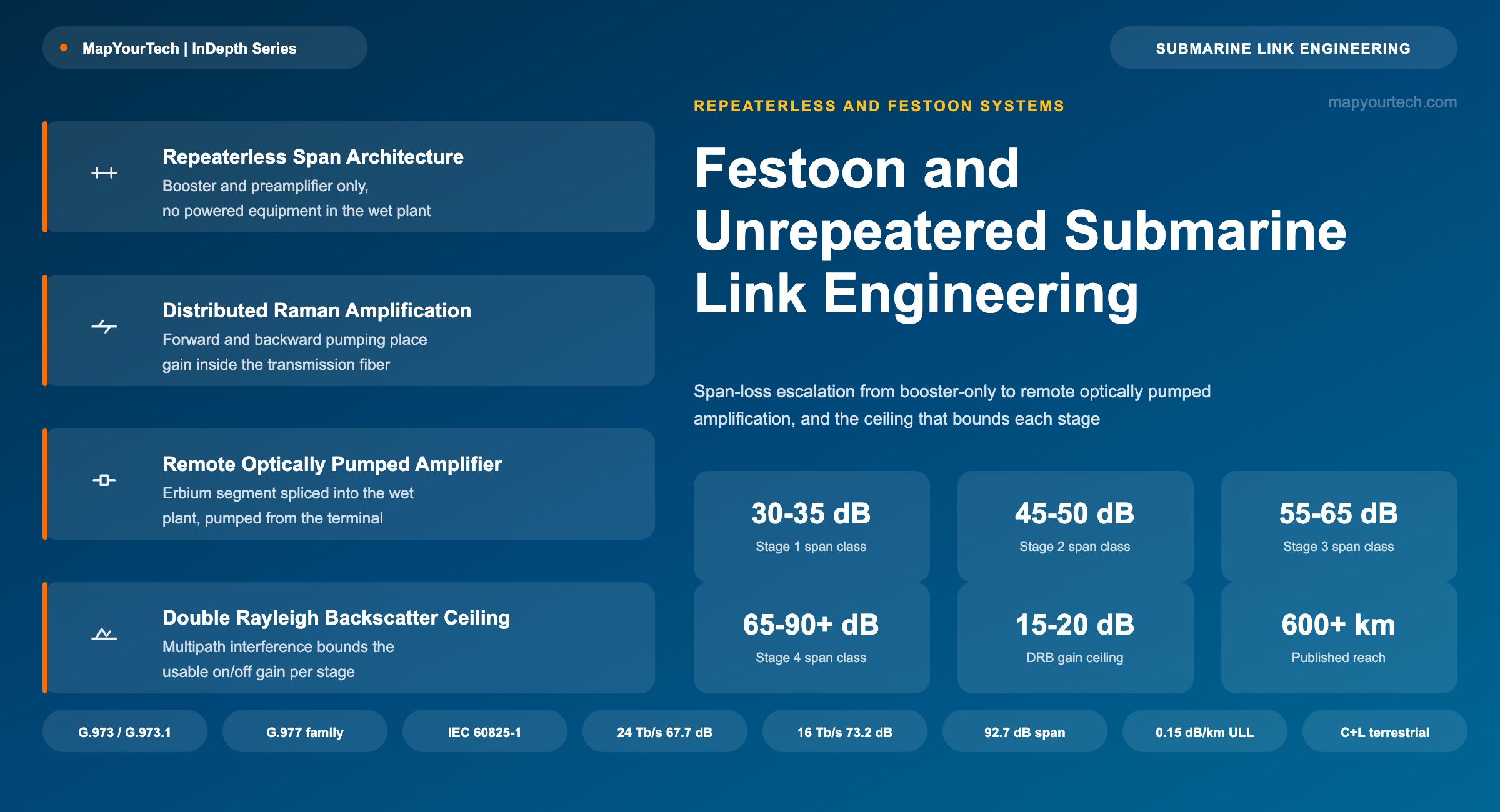
Festoon and Unrepeatered Submarine Link Engineering
The no-mid-span-amplifier constraint and the four-stage amplification ladder that closes span loss from the shore alone: boosters, backward and third-order Raman pumping, and remote optically pumped amplifiers.
1. Introduction
A repeatered submarine cable places a powered optical amplifier roughly every 60 to 100 km along the seabed, each one drawing electrical current fed from the shore stations through the cable's copper conductor. An unrepeatered or festoon link removes that chain entirely: from the moment the signal leaves the transmit terminal to the moment it reaches the receive terminal, nothing in the wet plant carries electrical power. Every dB of loss the fiber accumulates over that single unbroken span has to be closed from the two terminal buildings alone, using whatever combination of optical amplification techniques the terminal equipment can deliver without ever touching the cable itself.
That single constraint, no powered equipment between the terminals, is what separates festoon and unrepeatered engineering from every other class of optical transport design. It rules out the simplest fix for a marginal link, adding an amplifier partway along the route, and replaces it with a fixed escalation ladder: a high-power booster and preamplifier first, then a single stage of backward-pumped distributed Raman amplification, then forward pumping and higher-order cascaded Raman pumps working from both ends at once, and finally, where the physics and the economics both justify it, a remote optically pumped amplifier spliced directly into the glass with no electrical connection of its own. Each rung buys more span-loss budget. Each rung also adds cost, commissioning complexity, and new failure modes that a simple booster-and-preamplifier link never has to consider.
This article works through that ladder stage by stage: the physical mechanism each stage relies on, the reach class it typically delivers, the failure mechanism that eventually caps it, and the engineering judgment that decides when to climb to the next rung rather than accept the reach already on the table. The International Telecommunication Union's Telecommunication Standardization Sector, ITU-T, treats repeaterless and repeatered submarine systems as separate Recommendation families precisely because the design disciplines diverge this sharply: repeaterless systems fall under the G.973 series, while repeatered and regenerative systems are covered by G.977 and G.974 respectively.
Scope noteThis article covers point-to-point unrepeatered links and coastal festoon networks that connect several landing points with the same no-powered-equipment constraint on every span. It does not cover regenerative systems (ITU-T G.974), which restore the signal electrically at intermediate powered sites, or fully repeatered transoceanic cables (ITU-T G.977), which are a distinct engineering discipline built around the wet-plant amplifier chain itself.
The reach classes quoted throughout this article are typical engineering ranges, not fixed specifications. A given span's actual achievable loss budget depends on the fiber's effective area, its measured attenuation, the number and quality of splices, the channel count and per-channel rate the customer needs, and the specific amplifier hardware deployed at each terminal. Where a number comes from a published field trial or a vendor's public technical claim, this article states the source and the evidence class in the same sentence: standard-specified, measured, vendor claim, or theoretical limit. Where a figure is illustrative of a general trend rather than a specific measured or vendor-quoted result, the text and the accompanying figure say so explicitly.
2. Literature Review and Historical Context
ITU-T Standardization of Repeaterless Systems
ITU-T Recommendation G.973, Characteristics of repeaterless optical fibre submarine cable systems, has been revised across several editions since 1996, moving from PDH and SDH line rates up to 5 Gbit/s single-wavelength systems toward the DWDM-capable framework in use today. The Recommendation explicitly identifies the two techniques this article is built around: optical booster amplifiers and/or optical preamplifiers for the near-terminal gain stages, and remote optically pumped amplifiers as the mechanism for extending system length beyond what terminal-based amplification alone can reach.
G.973 sits inside a family of related Recommendations. G.973.1 specifies longitudinally compatible DWDM applications for repeaterless systems, defining optical interface parameters so that a transmit terminal from one supplier and a receive terminal from another can interoperate over the same cable plant. G.973.2 extends this to multichannel DWDM applications with single-channel optical interfaces. G.978 covers the physical and transmission characteristics of the submarine cable itself, common across G.973, G.973.1, G.974, and G.977 systems. G.974 and G.977 cover regenerative and repeatered systems respectively, the two architectures that unrepeatered and festoon design deliberately avoids.
From Booster-Only Links to Remotely Pumped Amplification
Early repeaterless systems relied on booster and preamplifier stages alone, which limited practical reach to a few hundred kilometers even with the erbium-doped fiber amplifier technology of the 1990s. Two developments moved that ceiling outward. The first was distributed Raman amplification, which turns the transmission fiber itself into a gain medium by injecting pump light at a wavelength roughly 100 nm shorter than the signal and relying on stimulated Raman scattering to transfer energy from pump photons to signal photons along the length of the span. The second was the remote optically pumped amplifier, commonly abbreviated ROPA: a short length of erbium-doped fiber spliced directly into the transmission path, with no local power source, that is pumped from a distance by high-power laser light launched from one of the terminals and delivered through the transmission fiber or a dedicated fiber in the same cable.
The published record of unrepeatered field trials traces this progression closely. A 2014 demonstration reported 1 Tbit/s (10 × 100 Gbit/s) transmission over 500.5 km of ultra-low-loss fiber with a total span loss of 79 dB, using optimized remotely pumped optical amplifiers and 100G DP-QPSK transponders requiring an OSNR of only 12 dB. In the same year, a separate trial reported 15 Tb/s unrepeatered transmission over 409.6 km (68.2 dB) of large effective-area fiber using forward and backward distributed Raman amplification together with a single ROPA, growing the channel count from 10 to 150 waves within a 61 nm amplification band and reporting a capacity-reach product of 6.14 Pb/s·km, a record figure at the time of publication. A related field result reported 557 km of unrepeatered 100G transmission using an enhanced ROPA design over cabled large effective-area ultra-low-loss fiber in an outside-plant environment, and a further study pushed single-channel and low-channel-count unrepeatered reach to 607 km at 100G and 632 km at 10G.
Read the Full Analysis with Premium
The remaining 88% of this article — the design numbers, trade-offs and field guidance — is part of MapYourTech Premium, along with the full premium library, courses and professional tools.
You May Also Like
-
Premium
-
September 1, 2026

-
Premium
-
September 1, 2026
-
Free
-
August 31, 2026