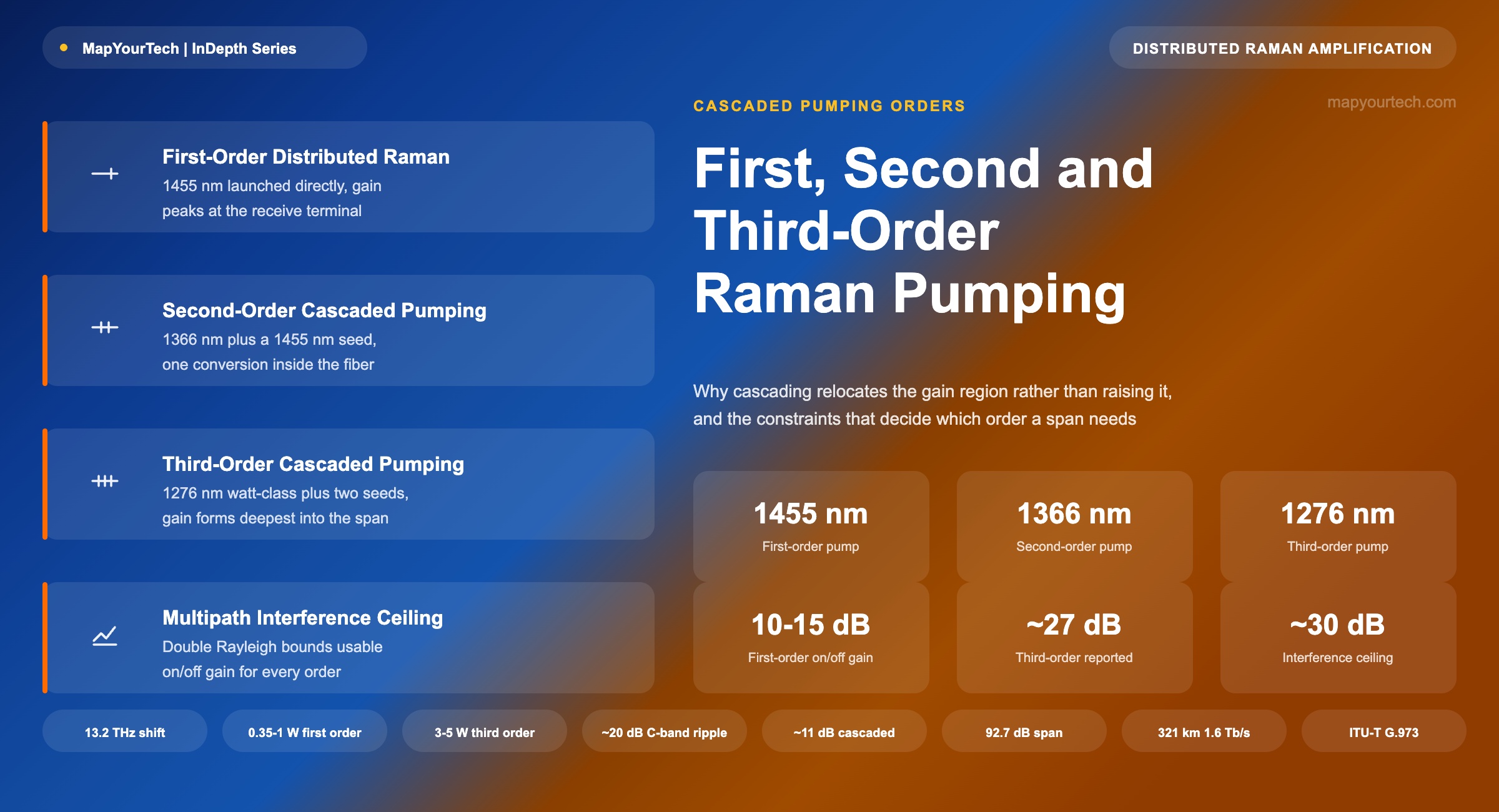
First, Second, and Third Order Raman Pumping
Why cascaded pumping moves the gain region rather than simply adding gain, and what that buys on spans with no mid-span amplifier.
Light brings us the news of the Universe.
— C.V. Raman1. Introduction
Distributed Raman amplification turns the transmission fiber itself into the gain medium. Pump light injected into the span transfers energy to the signal through stimulated Raman scattering, with peak transfer occurring when the signal sits about 13.2 THz below the pump in optical frequency — roughly 100 nm at 1550 nm. A pump near 1455 nm therefore amplifies C-band signals, and that pairing has been the standard arrangement in commercial line systems for two decades.
The pump wavelength that does the amplifying is not, however, the only wavelength a designer can launch. Higher-order pumping launches light at a shorter wavelength than the one needed for signal gain and relies on the fiber to build the useful pump internally, through a cascade of Raman conversions. Second-order pumping uses one intermediate conversion; third-order uses two. Published work has demonstrated cascades as deep as sixth order.
The reason to do this is not that higher-order pumping produces more gain in the abstract. It produces gain in a different place along the span, and it removes a launch-power ceiling that first-order pumping cannot escape. On unrepeatered and festoon links, where every dB of span loss must be closed from the two terminal buildings alone, those two differences decide whether a link closes at all. This article covers what each order is, the mechanism that separates them, and the constraints that keep higher-order pumping from being the default everywhere.
2. First-Order Distributed Raman Amplification
In first-order pumping, the pump that amplifies the signal is launched directly. For C-band transmission this means injecting roughly 1455 nm light into the fiber, normally from the receive terminal so that pump and signal counter-propagate. Counter-propagation is the standard choice because it averages the pump-signal interaction over the fiber and keeps pump intensity noise from transferring onto the signal, a problem that co-propagating schemes must actively manage.
The gain follows a compact expression in the small-signal regime, and the shape of that expression explains most of what first-order pumping can and cannot do.
G (dB) = 4.343 × gR × Pp × Leff

Leff = (1 − e−αpL) / αp
Two properties of the effective-length term govern first-order behaviour. Gain in dB rises linearly with launched pump power, so doubling the pump doubles the dB gain in this regime. Effective length, though, saturates: pump power attenuates as it travels, so once the span is longer than roughly the pump's own attenuation length, additional fiber adds no further interaction. For a fiber with 0.25 dB/km attenuation at the pump wavelength, effective length reaches 15.6 km at 40 km of span, 17.2 km at 80 km, and 17.4 km at 200 km. The amplification is described as distributed, but it is concentrated within the first several tens of kilometres from the pump launch point.
Practical Example — first-order gain on a standard span
A G.652 span of 80 km with 0.25 dB/km attenuation at the pump wavelength gives αp = 0.25/4.343 = 0.0576 km−1 and an effective length of (1 − e−0.0576×80)/0.0576 = 17.20 km. With gR = 0.35 W−1km−1 and 500 mW of launched pump power, the on/off gain is 4.343 × 0.35 × 0.50 × 17.20 = 13.1 dB. That figure sits inside the 10 to 15 dB range the literature identifies as achievable with practical pump levels, and it is the range in which commercial first-order line amplifiers are specified.
Takeaway: First-order pumping produces its gain close to the pump launch point, and its effective length stops growing beyond roughly 80 km of span. Additional reach must come from more pump power, which runs into a separate ceiling described next.
3. The Pump Power Ceiling in First-Order Pumping
If gain in dB scales linearly with pump power, the obvious step for a longer span is more pump power. First-order pumping blocks that step through a mechanism built into the same physics that produces the gain.
Stimulated Raman scattering does not distinguish between a pump and a signal. Any sufficiently intense wave in the fiber will transfer energy to whatever sits about 13.2 THz below it, including spontaneously generated light. A pump launched at 1480 nm has its own Raman gain peak at approximately 1583 nm. Increase that pump's power far enough and the fiber begins converting it to 1583 nm through amplified spontaneous Raman scattering, and in extreme cases through oscillation. The pump is depleted before it has done its intended work, and the converted light lands as noise inside the signal spectrum for any system using the L-band.
This sets a practical ceiling on how much first-order pump power can be launched, independent of laser capability. It is also why the reachable on/off gain of a first-order stage clusters in the 10 to 15 dB band rather than scaling with the size of the pump module.
Design ruleThe constraint is set by where the pump's own Stokes wavelength falls, not by the pump's absolute power. Any high-power wave launched into a transmission fiber will convert to a wavelength roughly 100 nm above itself, and the design question is whether that wavelength is harmless or lands on the signal.
4. Cascaded Pumping: Second and Third Order
Cascaded pumping avoids the ceiling by moving the high-power launch to a wavelength whose Stokes shift lands far from any signal. Rather than launching 1455 nm directly, a shorter primary wavelength is launched at high power alongside one or more low-power seed sources. Each seed marks a step in the conversion chain, and the fiber performs the conversions.
The naming convention counts Stokes steps from the launched primary wavelength to the signal.
| Order | Conversion chain | Steps | Measured shifts |
|---|---|---|---|
| First | 1455 nm → signal | 1 | 12.6 THz |
| Second | 1366 nm → 1455 nm → signal | 2 | 13.4, 12.6 THz |
| Third | 1276 nm → 1355 nm → 1455 nm → signal | 3 | 13.7, 15.2, 12.6 THz |
Every shift in the table sits on the silica Raman gain curve, which peaks near 13.2 THz and retains useful gain over a considerably wider offset. The third-order chain is the arrangement used in commercially available high-power pump subsystems for unrepeatered links, where a primary source near 1276 nm carries the energy and seeds at 1355 and 1455 nm define the path it converts along. Vendor literature for such subsystems quotes primary output power up to 3 W, an order of magnitude above what direct 1455 nm launch permits.
A 1276 nm primary has its own Raman gain peak near 1352 nm, well away from the transmission window. The self-depletion mechanism that caps first-order launch power does not apply, because the wavelength the pump converts into is one the design wants it to reach.
Variants of the arrangement replace a seed source with a fiber Bragg grating that reflects spontaneously scattered light back into the span, letting the cascade build from noise rather than from an injected seed. Bidirectional and ultra-long fiber laser configurations extend the same principle further, and published unrepeatered experiments have used them to reach 240 km of standard single-mode fiber at 52.7 dB of span loss carrying a 28 GBd 64QAM signal.
5. Gain Region Relocation and Noise Figure
The launch-power advantage is only half of what cascaded pumping delivers, and arguably the smaller half. The more consequential effect is where the gain forms.
With first-order pumping, pump intensity is highest at the launch point and decays from there, so the gain peak sits at the receive terminal. That is the least useful place for it. The signal arriving at the terminal has already traversed the full span and reached its lowest power, and any noise the amplification adds at that point travels directly into the receiver without further attenuation.
In a cascaded scheme the useful 1455 nm power does not exist at the launch point. It has to be built through one or two conversions, which takes distance. The gain peak consequently forms tens of kilometres deeper into the span, where the signal is weaker and gain is worth more, and where the noise generated is subsequently attenuated by ordinary fiber loss on its way to the receiver. The result is a lower effective noise figure for the amplification chain, and a flatter signal power profile along the span, which also reduces the accumulated nonlinear penalty.
This is the reason higher-order pumping improves link margin rather than simply adding gain. Published results reflect it directly: an early second-order demonstration carried 1.6 Tb/s over 321 km of unrepeatered fiber, and third-order distributed amplification has been used in field transmission of 8 × 170 Gb/s over a high-loss standard single-mode fiber link.
Takeaway: Cascaded pumping is better understood as gain relocation than as gain increase. Moving the amplification region away from the receive terminal improves noise figure and flattens the power profile, and those two effects produce most of the margin improvement.
6. Order Comparison
| Attribute | First order | Second order | Third order |
|---|---|---|---|
| Launched sources | 1455 nm at high power | 1366 nm at high power, 1455 nm seed | 1276 nm at high power, 1355 and 1455 nm seeds |
| Conversions inside the fiber | None | One | Two |
| Gain peak location | At the receive terminal | Tens of km into the span | Deepest into the span |
| Launch power ceiling | Capped by self-conversion near 1583 nm | Higher | Highest; primary Stokes falls near 1352 nm |
| Effective noise figure | Baseline | Improved | Best of the three |
| Double Rayleigh penalty | Lowest | Higher than first order | Highest |
| Gain bandwidth per cascade | Set by pump count | Narrow | Narrow |
| Hardware complexity | Lowest | Moderate | Highest |
| Typical application | Standard line systems | Long spans, research links | Unrepeatered and festoon extremes |
Pump Configuration and Reported Gain
The qualitative comparison above becomes a design tool only when the pump powers, gain figures and gain-region positions behind it are stated. The values below are drawn from the patent and conference literature listed in Section 10; each carries its basis, because reported laboratory maxima and typical field provisioning are not the same quantity.
| Parameter | First order | Second order | Third order | Basis |
|---|---|---|---|---|
| Primary launched wavelength | 1450–1455 nm | 1366 nm | 1276 nm | literature |
| Seeds or gratings required | None | 1455 nm seed or FBG pair | ~1360 and ~1427 nm | literature |
| Primary launch power, reported | 0.35–1 W | 0.6–2 W | 3–5 W | reported experiments |
| Where the useful 1455 nm exists | At the fiber facet | Builds over the first few km | Builds roughly 25 km in | modelled and measured |
| Useful gain region | Last ~20–25 km of the span | Deeper than first order | Peak ~25 km from the terminal | modelled |
| On/off gain, typical to reported maximum | 10–15 dB | 15–20 dB | up to ~27 dB | typical / reported |
| Gain variation across the C-band | ~20 dB | — | ~11 dB | patent measurement |
| Multipath interference ceiling | ~30 dB | ~30 dB | ~30 dB | patent measurement |
| Pump self-conversion Stokes wavelength | ~1583 nm, lands in L-band | ~1455 nm, useful | ~1352 nm, harmless | Stokes arithmetic |
Two rows carry most of the engineering weight. The multipath interference ceiling near 30 dB applies to every order, so cascading does not raise the maximum usable on/off gain — it changes where that gain can be placed and how flat it is across the band. And the gain variation across the C-band, roughly 20 dB for direct first-order pumping against roughly 11 dB for a third-order cascade, is why the top of the C-band becomes unusable under aggressive first-order pumping: gain there crosses the interference ceiling before the rest of the band has enough.
Reported Unrepeatered Demonstrations
| Pumping scheme | Reach | Span loss | Capacity | Fiber |
|---|---|---|---|---|
| Second order, distributed | 321 km | — | 1.6 Tb/s | Standard single-mode |
| Second order, random DFB first-order seed | 352.8 km | — | DP-QPSK | Standard single-mode |
| Dual order, first plus second | 240 km | — | 64QAM | SMF-28 |
| Second order with remote amplification | 500 km | — | 12 × 10 Gbit/s | Ultra-large effective area |
| First plus second order co-pumping | — | 92.7 dB | 8 × 100G | Not stated |
| Third order, distributed, field | — | high-loss link | 8 × 170 Gb/s | Standard single-mode |
Reach and span loss are reported inconsistently across this literature, which is itself worth noting: a kilometre figure without the accompanying loss says little, because the same distance over ultra-large effective-area fiber and over standard single-mode fiber are different engineering problems. Where a demonstration reports span loss rather than distance, as the 92.7 dB co-pumped result does, that is the more transferable number.
7. Constraints on Higher-Order Pumping
Double Rayleigh Backscattering
A small fraction of the signal is Rayleigh backscattered at every point in the fiber. Under distributed gain that backscattered light is amplified as it travels backward, and a second scattering event sends part of it forward again as a delayed, independently phased copy of the signal. The result is multipath interference at the receiver. Because this is a beat-noise mechanism rather than a spontaneous-emission one, it does not average out over the receiver's integration time, and it therefore imposes a ceiling rather than a gradually worsening penalty.
Published characterisations place the onset of appreciable multipath interference degradation at roughly 15 to 20 dB of distributed on/off gain for first-order pumping. Higher-order schemes carry more double Rayleigh backscattering than first-order at equal gain, not less; measurements of second-order amplifiers show an increase over first-order, and the net benefit has to be assessed through a full Q-factor analysis rather than assumed from the noise-figure improvement alone.
Gain Bandwidth
A single pump wavelength produces useful Raman gain over roughly 25 to 30 nm. Covering the C-band alone takes about 35 nm; covering C and L together spans approximately 95 nm. Constructing a 100 nm amplification band with under 1 dB of gain ripple takes as many as eight pump wavelengths spread between about 1430 and 1520 nm.
A cascade works in the opposite direction. It concentrates the launched energy into a single final pump line, which is what gives it the power advantage in the first place. Commercial third-order subsystems are accordingly specified for the C-band, and co-pumped variants for a narrower portion of it. Wide-band Raman amplification and deep cascading are competing design objectives rather than complementary ones, which is why broadband systems use many moderate-power pumps and unrepeatered systems use one deep cascade.
Pump-to-Pump Interaction
Where multiple pump wavelengths are used together, the same Raman process that amplifies signals also operates between the pumps. Shorter-wavelength pumps transfer energy to longer-wavelength pumps before either reaches the signal, so the short-wavelength pumps require disproportionately more power than a calculation ignoring the interaction would suggest. Published analysis finds that above about 10 dB of gain, increasing any pump's power tilts the gain profile further toward the long-wavelength side, and that this caps achievable flat gain across a 75 nm signal range at approximately 19 dB. Four-wave mixing between closely spaced pumps can also generate products inside the signal band, particularly on fiber with low dispersion at the pump wavelengths.
Fiber characterisationPump efficiency depends on fiber attenuation at the pump wavelength, not at the signal wavelength. Legacy fiber without a suppressed water peak carries excess loss in the 1383 to 1450 nm region where the pumps sit, and even 0.05 dB/km of excess there shortens the effective pump length materially. Bidirectional characterisation at pump wavelengths, not only at 1550 nm, belongs in the design workflow for any Raman-assisted span.
8. Selecting a Pumping Order
The selection follows the span budget rather than a preference for one technology. First-order pumping is the correct choice wherever the loss budget closes within its 10 to 15 dB contribution, because it carries the lowest cost, the simplest commissioning sequence, and the least double Rayleigh backscattering. Standard terrestrial line systems with amplifier huts every 80 to 100 km sit comfortably in this category, and adding a deep cascade there buys nothing that justifies its cost.
Second and third-order pumping earn their place where no intermediate amplification site exists and the span budget exceeds what terminal amplification plus first-order Raman can close. Unrepeatered submarine links, coastal festoon systems, and long optical ground wire routes are the recurring cases. In those designs the order is chosen by working the loss budget: characterise the fiber, compute the budget at end of life with an allowance for future repairs, and step up an order only when the rung below it falls short.
Two constraints shape the decision alongside the budget. Higher-order pumping is a C-band technique in its commercially available forms, so a route requiring C and L operation on the same fiber will not find its answer here. And the pump powers involved place these systems firmly inside laser safety regulation, which makes an interlock tied to supervisory channel presence, along with a staged power ramp and back-reflection monitoring during turn-up, part of the design rather than an operational afterthought.
Takeaway: Choose the lowest order that closes the repair-margined end-of-life budget. Each step up buys reach and costs double Rayleigh backscattering, commissioning complexity, and usable bandwidth.
9. Conclusion
The distinction between first, second, and third-order Raman pumping is not a hierarchy of quality. It is a choice about where in the fiber the amplification happens, purchased by accepting a longer conversion chain and the penalties that come with it. First-order pumping places gain at the terminal and stops where the pump's own Stokes wavelength begins to consume it. Cascaded pumping moves the launch to a wavelength the fiber can carry at far higher power, and lets the span itself construct the amplifying wavelength deeper in, where it is worth more.
What the cascade cannot do is be broad. Concentrating energy into a single final pump line is the mechanism, and spreading energy across many pump lines is what wide-band amplification requires. Engineers working multi-band capacity growth and engineers working unrepeatered reach are therefore pulling the same physics in opposite directions, and will continue to, until an amplification technology arrives that does not force the choice.
10. References
- Papernyi, Karpov and Clements — Cascaded Pumping System and Method for Producing Distributed Raman Amplification in Optical Fiber Telecommunication Systems, United States Patent 6480326.
- Papernyi, Karpov, Ivanov and Clements — Cascaded Pump Delivery for Remotely Pumped Erbium-Doped Fiber Amplifiers, United States Patent 7508575.
- Papernyi, Karpov and Clements — Third-Order Cascaded Raman Amplification, Optical Fiber Communication Conference.
- Papernyi, Ivanov, Koyano and Yamamoto — Sixth-Order Cascaded Raman Amplification, Optical Fiber Communication Conference.
- Labrunie, Boubal, Brandon and others — Unrepeatered Transmission over 321 km Using Second-Order Pumping Distributed Raman Amplification, Optical Amplifiers and Their Applications.
- Schneiders, Vorbeck, Leppla, Lach, Schmidt, Papernyi and Sanapi — Field Transmission over High-Loss Standard Single-Mode Fiber Link Using Third-Order Distributed Raman Amplification, IEEE Journal of Lightwave Technology.
- Iqbal, Tan and Harper — Unrepeatered 64-QAM Transmission over Standard Single-Mode Fiber Using Distributed Raman Amplification, Applied Sciences.
- Ania-Castañón and others — High Order Fiber Raman Amplifiers, United States Patent 6700696.
- Stentz and others — Optical Communication System Using Multiple-Order Raman Amplifiers, United States Patent 6163636.
- Tan, Iqbal, Ania-Castañón and Harper — Unrepeatered DP-QPSK Transmission over 352.8 km SMF Using Random DFB Fiber Laser Amplification, IEEE Photonics Technology Letters.
- Fludger, Handerek and others — Novel Ultra-Broadband High Performance Distributed Raman Amplifier Employing Pump Modulation, Optical Fiber Communication Conference.
- RP Photonics Consulting — Raman Amplifiers, Encyclopedia of Laser Physics and Technology.
- ITU-T G.973 — Characteristics of Repeaterless Optical Fibre Submarine Cable Systems, ITU-T Study Group 15.
- IEC 60825-1 — Safety of Laser Products, Part 1: Equipment Classification and Requirements, International Electrotechnical Commission.
- Sanjay Yadav, "Optical Network Communications: An Engineer's Perspective" – Bridge the Gap Between Theory and Practice in Optical Networking.
Related Articles on MapYourTech