MapYourTech | MapYourBasics Series
Span Loss Capability and GOSNR Margin: Two Separate Ceilings in Long-Span Design
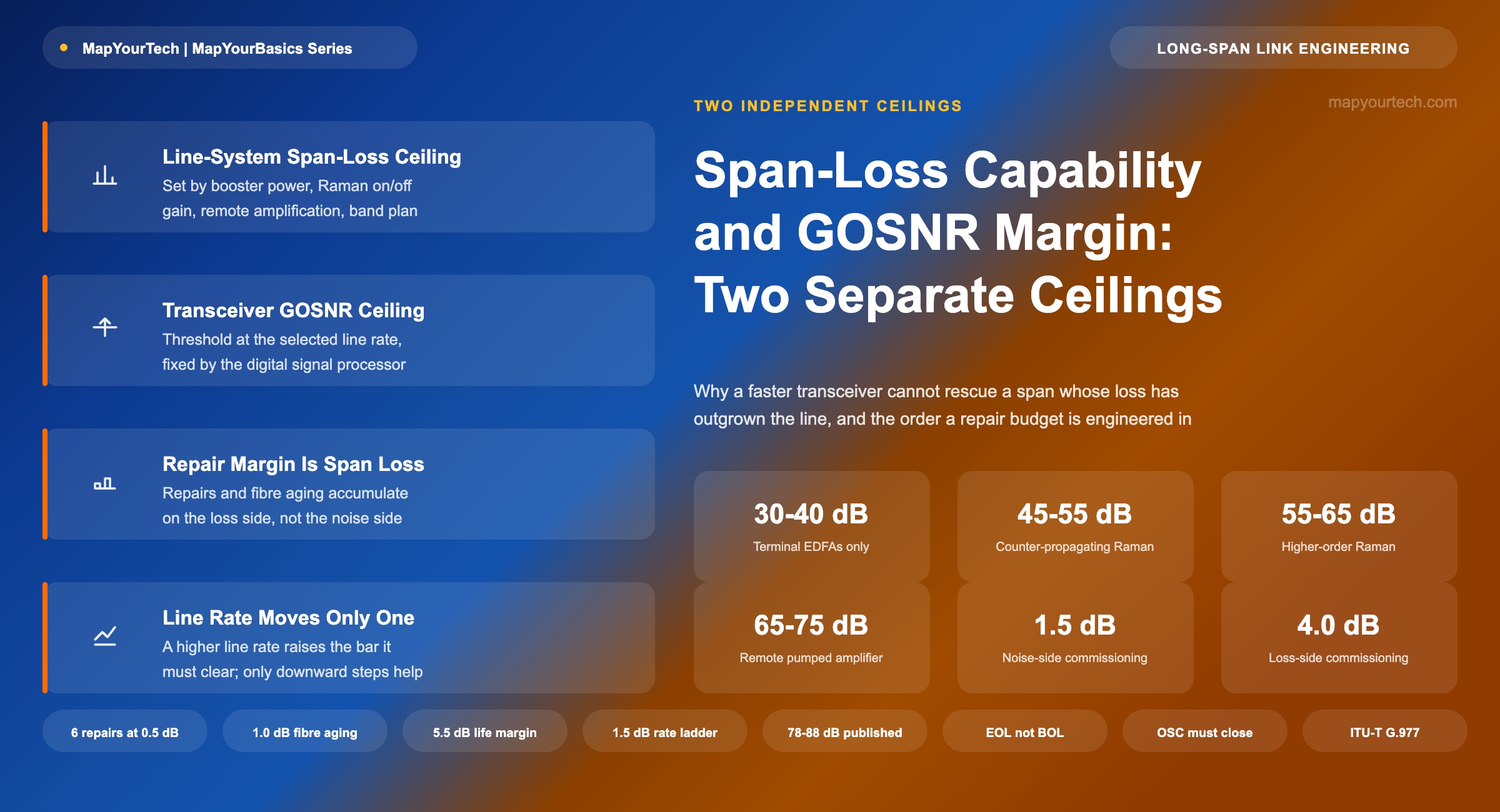
A long span fails in one of two distinct ways: the amplifier line runs out of span-loss capability, or the transceiver runs out of GOSNR margin. The levers that move each ceiling are different, and confusing them leads to proposals that cannot work - such as expecting a higher-rate transceiver to absorb a repair budget.
The best network design is one that anticipates tomorrow's needs.
Introduction
A single-span link between two terminals - an island interconnect, a coastal crossing, a long terrestrial hop with no room for an intermediate site - is engineered against two limits at once. The first is the span loss the amplifier line can carry: a property of the boosters, the distributed Raman amplification, any remote gain element, and the band plan. The second is the generalized optical signal-to-noise ratio (GOSNR) the transceiver requires at its chosen line rate. Because both limits are stated in decibels, they are easy to conflate, and the most common form of that confusion is the belief that a newer, faster transceiver can rescue a span whose loss has grown past what the line supports. This article separates the two ceilings, names the levers that move each one, and sets out the order in which a repair-margin requirement is engineered.
The Two Ceilings of a Long Span
The line-system ceiling is a capability statement: the maximum end-of-life span loss at which the amplifier chain still delivers its specified gain, supervisory reach, and noise performance. It is fixed by hardware and physics - the saturated output power of the booster, the on-off gain the Raman pumps can develop in the installed fiber, whether a remote optically pumped amplifier sits in the span, and whether one band or two share the launch power. The transceiver ceiling is a threshold statement: the minimum GOSNR at which the receiver's forward error correction still closes at the chosen rate and modulation. It is fixed by the digital signal processor and rises with every step of line rate. These are independent specifications checked against different quantities - one against accumulated loss, one against accumulated noise - and a design must clear both.
Takeaway: A long span passes only when the end-of-life loss sits under the line-system ceiling and the delivered GOSNR sits over the transceiver threshold. The two checks use different physics and different levers, and neither can substitute for the other.
Repair Margin as Accumulated Span Loss
A repair-margin requirement is a statement about future loss, not about future noise. Every marine repair inserts additional fiber and splices, and field practice budgets each event at a few tenths of a decibel; fiber aging adds a slow further contribution over the system's life. These allowances are added to the installed span loss, and the sum - the end-of-life loss - is what the amplifier line must carry on the day the last budgeted repair has happened. The check therefore runs against the line-system ceiling first, before any transceiver threshold is consulted. If the summed loss exceeds what the line supports, the design has already failed, and it has failed at every line rate simultaneously: no threshold, however low, is reached by a signal the line can no longer amplify within specification.
Takeaway: Repair events and aging are consumed as span loss. A repair-margin requirement is met or missed by the amplifier line, and a design that fails this check fails at all rates at once.
Margin Hierarchy from Beginning of Life to End of Life
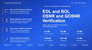
Repair allowance is one entry in a larger budget, and the budget is organized around two reference states. Beginning of life (BOL) is the as-built condition measured at commissioning: installed span loss, new fiber, amplifiers at nominal performance, every allowance intact. End of life (EOL) is the design condition after every budgeted allowance has been consumed - all repair events executed, fiber and equipment fully aged - and EOL, not BOL, is the state a design commitment is signed against. Between the two states sits a hierarchy of allowances, each consumed by a different mechanism and owned by a different part of the design.
The loss-side allowances accumulate as span loss and are checked against the line-system ceiling. Marine repair events are budgeted at a few tenths of a decibel to one decibel each in field practice, with the event count set by cable length and the route's fault history; fiber aging adds a slow attenuation growth commonly planned at a few thousandths of a decibel per kilometre per year, which on a long span integrates to a material figure over a multi-decade life. The noise-side allowances are consumed as GOSNR: equipment aging covers pump, transmitter and receiver drift and is typically allocated well under a decibel by vendor design rules; the nonlinear allowance - commonly a fixed reservation of about one decibel in industry threshold conventions - separates the GOSNR threshold from the OSNR threshold and belongs to the line's launch condition. Two further entries frame the stack. The transceiver threshold itself already contains the modulation, forward error correction and implementation penalties, so no separate implementation margin is added outside it. And the unallocated system margin - a design-policy reserve commonly held at half a decibel to two decibels - is deliberately assigned to nothing: it is the buffer against what was not budgeted, and it is spent last.
| Allowance | Consumed As | Typical Allocation | Example | Owner and Lever |
|---|---|---|---|---|
| Repair allowance | Span loss | 0.5 dB per marine repair event is a common planning figure; the event count follows cable length and route fault history (field practice) | 3.0 dB | Line system; absorbed by amplifier architecture |
| Fiber aging | Span loss | Commonly planned as a lumped 0.5 to 1 dB per span over a 25-year life (field-typical) | 1.0 dB | Line system; absorbed by amplifier architecture |
| Equipment aging | GOSNR | 0.3 to 0.5 dB over life for transmitter, receiver and pump drift (vendor design rules) | 0.5 dB | Line system; amplifier and terminal specification |
| Nonlinear allowance | GOSNR | 1 dB fixed reservation in common threshold conventions (industry practice) | 1.0 dB | Line design; launch-power optimization |
| Implementation penalty | Inside the threshold | Contained in the published transceiver threshold (vendor specification) | — | Transceiver; not separately budgeted |
| Unallocated system margin | GOSNR reserve | 0.5 to 2 dB, held against unbudgeted effects (design policy) | 1.0 dB | Design policy; spent last, assigned to nothing |
Practical Example — a representative end-of-life margin budget
Using the illustrative allocations of Table 1 for a long single span: six budgeted marine repairs at 0.5 dB each contribute 3.0 dB, fiber aging a further 1.0 dB - 4.0 dB in total consumed as span loss, which the amplifier line must carry at end of life. On the noise side, equipment aging takes 0.5 dB of GOSNR and the unallocated system margin holds 1.0 dB in reserve, while the 1.0 dB nonlinear allowance already separates the GOSNR threshold from the OSNR threshold. The commissioning requirement that follows is direct: the BOL-delivered GOSNR must sit at least 1.5 dB above the threshold on the noise side, and the line-system ceiling must exceed the installed loss by at least 4.0 dB on the loss side - 5.5 dB of total budgeted life margin, before the threshold itself is counted. Every figure here is illustrative and field-typical; a real project takes its event count from the route's fault statistics and its aging figures from the cable supplier's specification.
Margin policy becomes easy to state once the erosion is drawn: remaining margin falls one decibel for every decibel of consumed allowance, so the BOL margin at the committed rate is exactly the number of decibels of life events the design survives.
A further end-of-life check applies to the line side alone: the optical supervisory channel must itself survive the end-of-life loss, because a span whose traffic still closes but whose supervision does not is unmanageable. On the deepest spans this check, not the traffic channel, is sometimes the binding one - another reason the EOL loss sum is evaluated against the line system before any transceiver threshold enters the analysis.
Takeaway: A design is committed at EOL, verified at BOL, and the difference between the two states is the margin hierarchy. Loss-side allowances are absorbed by the amplifier architecture, noise-side allowances by the GOSNR budget, and the unallocated reserve covers only what was never budgeted.
Line-System Capability and Its Levers
The levers that raise span-loss capability all live in the amplification architecture. Launch power is the first: a booster with higher saturated output raises the power entering the fiber, and every decibel of launch is a decibel of loss recovered - bounded by the nonlinear penalty it creates, which is why launch optimization and OSNR budgeting are inseparable. Band choice is the second: a single-band line concentrates the available launch power into one band and removes the inter-band stimulated Raman scattering that transfers power between bands in a dual-band system, which is why single-band lines are specified for deeper spans than dual-band lines of the same hardware family. Distributed Raman gain is the third: counter-propagating pumps convert the last tens of kilometres of the transmission fiber into gain medium, improving the noise figure of the receive end precisely where the signal is weakest, with higher-order pumping schemes pushing that gain deeper into the span. A remote optically pumped amplifier is the fourth, placing erbium gain inside the span itself for the longest unrepeatered links. The transceiver appears nowhere in this list.
Where: Pin is the per-channel power entering the amplifying stage in dBm (typical range −35 to +5 dBm), NF is the stage noise figure in dB (roughly 4 to 7 dB for discrete erbium amplifiers, near or below 1 dB effective for distributed Raman gain), and 58 dB is the reference constant for a 0.1 nm noise bandwidth at 1550 nm. Stage contributions combine as noise powers, so the weakest point of the span dominates.
As an illustration with round numbers: a stage fed at −30 dBm with a 5 dB noise figure contributes a stage OSNR of 23 dB, and no later stage can recover what is lost here - which is exactly why gain placed inside the span through Raman pumping outperforms the same gain placed after it.
Takeaway: Span-loss capability is bought with launch power, band concentration, distributed Raman gain, and remote amplification. Each lever changes where and how strongly the signal is amplified; none of them involves the transceiver.
Line Rate and the GOSNR Threshold Ladder
The transceiver's lever works on the other ceiling, and it works in the direction opposite to the common intuition. At a fixed symbol rate, each step of line rate packs more bits into every symbol, and the required GOSNR rises with rate and modulation order - roughly one and a half to two decibels per step for current coherent designs - a field-typical figure that grows steeper toward the top of a device's rate range. A transceiver at twice the rate therefore needs several decibels more GOSNR, not less: higher rate consumes margin. Running a new-generation device below its maximum rate does spread the same bits across more symbols and lowers the per-symbol requirement, but the gain is measured in tenths of a decibel once the higher symbol rate's own implementation penalty is subtracted - useful headroom, never a substitute for line capability. The one contribution line-rate selection makes to a repair budget is downward: stepping the line rate down lowers the threshold and converts the difference into margin that repairs can consume, provided the line itself still carries the end-of-life loss. The relationship between the delivered GOSNR and the underlying OSNR is fixed by the nonlinear penalty of the launch condition, which is part of the line design, not the transceiver's.
Practical Example — a repair budget evaluated against both ceilings
Consider a coastal single-span crossing engineered near the capability limit of a dual-band line, with the customer requiring a multi-decibel repair allowance over the system's life. Adding the allowance to the installed loss pushes the end-of-life figure past the dual-band ceiling, so the dual-band design fails at every rate before any threshold is checked - and a faster transceiver changes nothing, because its threshold is higher still. The workable designs all act on the line: concentrating launch power into a single band raises the ceiling enough to carry the summed loss, after which the rate is chosen so the delivered GOSNR clears the threshold with the repair allowance intact; alternatively, a remote optically pumped amplifier restores enough noise performance to keep the original rate. In every workable variant, the line architecture absorbed the repair budget and the line-rate selection tuned the remaining margin - never the reverse.
Takeaway: Rate moves the threshold, and only downward line-rate steps create margin. A higher-rate transceiver raises the bar it must itself clear, and no transceiver moves the span-loss ceiling.
Design Sequence for a Repair-Margin Requirement
The two-ceiling structure fixes the order of work. First, sum the end-of-life loss: the BOL installed loss plus the full repair allowance plus fiber aging. Second, check that sum against the line-system capability of the intended architecture, and if it fails, change the architecture - band plan, Raman gain, remote amplification, launch power - until it passes, because nothing downstream can repair this step. Third, compute the OSNR and GOSNR the passing architecture delivers at end of life, including the nonlinear penalty of its launch condition. Fourth, select the highest line rate whose threshold sits below the delivered GOSNR by at least the margin policy, and state explicitly how many repair events that margin absorbs. The optimization levers available at each band configuration differ enough that steps two and three usually iterate once; steps one and four never trade places.
| Property | Line-System Ceiling | Transceiver Ceiling |
|---|---|---|
| Checked against | End-of-life span loss | Delivered end-of-life GOSNR |
| Set by | Booster power, Raman gain, remote amplification, band plan | Modulation, symbol rate, forward error correction, implementation |
| Moved by | Amplifier architecture changes | Line-rate and format selection |
| Consumes the repair budget | Yes - directly, as added loss | Only through the margin left above threshold |
| Response to a higher line rate | Unchanged | Threshold rises; margin decreases |
Conclusion
Span loss and GOSNR are both decibel quantities, but they are spent from different accounts. The repair budget a customer asks for is drawn from the line system's loss account, and only the amplification architecture can fund it; the rate a transceiver runs at is drawn from the noise account, and only downward line-rate steps put anything back. Engineers who keep the two accounts separate produce designs that state plainly what each element contributes - and can explain, when a faster transceiver is proposed as the fix for a deep span, why the proposal moves the wrong ceiling in the wrong direction. That clarity, more than any single technology choice, is what makes a long-span design defensible for the decades it is expected to serve.
References
- ITU-T G.977.1 — Transverse compatible dense wavelength division multiplexing applications for repeaterless optical fibre submarine cable systems, ITU-T Study Group 15.
- ITU-T G.680 — Physical transfer functions of optical network elements, ITU-T.
- P. Poggiolini, The GN Model of Non-Linear Propagation in Uncompensated Coherent Optical Systems, Journal of Lightwave Technology.
- Sanjay Yadav, "Optical Network Communications: An Engineer's Perspective" — Bridge the Gap Between Theory and Practice in Optical Networking.
Related Articles on MapYourTech