Space-Division Multiplexing System Design: Multicore Fiber, Coupling Management and Submarine Economics
Multicore and few-mode transmission, inter-core crosstalk and coupling management, and the fiber-pair and multicore economics already carrying live submarine traffic.
A design case is a promise about the worst day, not the average one.
Learning Outcomes
- Define a spatial channel and compute the total spatial multiplicity of a multicore cable from its core, mode and fiber-pair counts.
- Distinguish uncoupled, systematically-coupled and randomly-coupled multicore fiber by their crosstalk behavior and MIMO-DSP requirements.
- Apply the coupled-power crosstalk model to size a per-span budget against a target end-of-link penalty, as in the −50 dB/span case worked through in Section 4.
- Compare core-pumped and cladding-pumped multicore EDFA architectures on gain, noise figure and per-core electrical power draw.
- Read the design trade-off between cladding diameter, core pitch and mechanical reliability directly off a multicore fiber cross-section.
- Place the 12-to-24 fiber-pair submarine SDM cables now in service and the first commercial multicore fiber deployment on one capacity timeline.
- Recognize the field signatures of bend-induced crosstalk, splice misalignment and amplifier gain imbalance in a deployed multicore link.
1. Introduction
A single strand of single-mode fiber guides exactly one spatial path, and coherent transponders now run that path within roughly 1 dB of the Shannon limit for a given symbol rate and reach (approximate industry figure). Probabilistic constellation shaping and multi-terabit single-carrier wavelengths have removed most of the coding gap that once separated deployed hardware from the theoretical bound: Ciena's WaveLogic 6 Extreme runs a programmable symbol rate up to 200 GBd and carries 1.6 Tb/s on a single carrier at metro reach, and 800 Gb/s across transoceanic distances (vendor-specified). Once a transponder generation operates that close to the bound, the paths left for adding capacity are widening the optical band toward C+L and eventually S+C+L, or adding parallel spatial paths through space-division multiplexing (SDM).
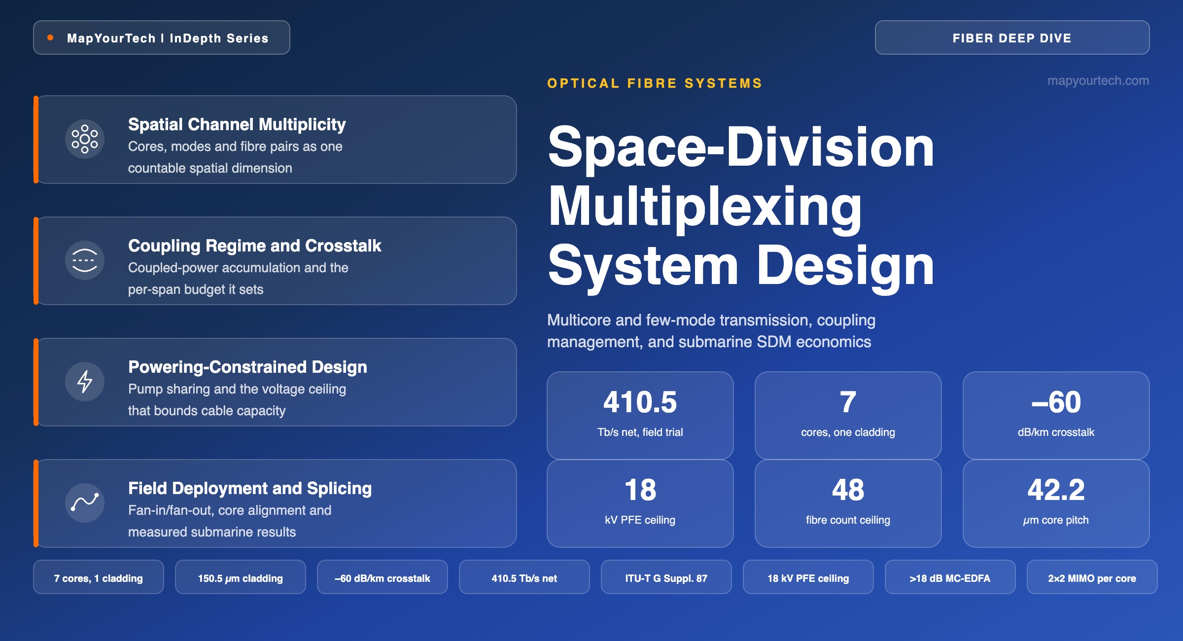
Submarine cable systems reached this point first, because the electrical power available to feed undersea optical amplifiers is fixed by the power-feed equipment at each landing station, and pushing more power into a fixed number of spatial paths runs into fiber nonlinearity long before it runs into the amplifier noise floor. Two fiber-level approaches implement the spatial dimension in response. The first already carries the majority of new submarine traffic: packaging more single-mode fiber pairs into one cable. Systems that shipped 4 to 8 fiber pairs a decade ago now ship 12 to 24; Google's Dunant cable introduced pump-sharing amplification across a 12-fiber-pair design when it entered service in 2021, and Meta's 2Africa system carries up to 16 fiber pairs across its 45,000 km route. The second approach packages more than one core, or more than one guided mode, inside a single strand of glass with one shared cladding — multicore fiber (MCF) and few-mode fiber (FMF). A 2026 field trial between two islands in the South China Sea carried a net 410.5 Tbit/s through a single 7-core fiber over a 140 km link using a cladding-pumped multicore erbium-doped fiber amplifier (MC-EDFA), and Google's Taiwan-Philippines-US (TPU) cable is bringing two-core fiber into commercial submarine service on its Taiwan and Philippines branch segments in 2026 — the first commercial deployment of multicore fiber in a submarine cable system.
The two approaches are not competitors so much as points on the same spatial-parallelism spectrum, and a design team chooses between them based on what the cable's mechanical envelope, its landing-station space, and its amplifier technology can support at the time of the build. This article works through the physics that makes multicore and few-mode transmission possible, the crosstalk and coupling behavior that separates a workable design from an unworkable one, the amplifier architectures that turn a multicore fiber into a system rather than a laboratory sample, and the fiber-pair economics that are the version of SDM already carrying live traffic today.
2. Spatial Channel Definition and Multiplicity
A spatial channel is an independently addressable light-guiding path within a strand of optical fiber — created by a distinct core, a distinct guided mode, or a distinct physical fiber — capable of carrying its own set of wavelength-division-multiplexed signals. Space-division multiplexing is the practice of increasing the number of spatial channels available for a given cable cross-section or duct allocation.
Three adjacent quantities get conflated with the spatial channel, and each names a different thing. A core is the physical waveguide — the region of raised refractive index that confines light — and in a single-mode core it supplies exactly one spatial channel; in a few-mode core it supplies as many spatial channels as the core guides linearly polarized (LP) mode groups. A fiber pair is the conventional non-multicore unit of spatial parallelism: two physical strands of glass, one per transmission direction, each an independent single-mode spatial channel with its own connectors, splices, and amplifier chain. A wavelength channel sits on an entirely separate axis: it multiplies with the spatial dimension rather than substituting for it, since every spatial channel can carry its own full set of wavelength-division-multiplexed signals.
The arithmetic that ties these together is one line: total spatial multiplicity M = (fiber pairs per cable) × (cores per fiber) × (spatial modes per core). A single 7-core, single-mode fiber, four of which run inside one field-deployed submarine cable, gives M = 4 × 7 × 1 = 28 spatial channels in that cable, each independently loaded — in the 2026 field trial referenced above — with 374 wavelength channels split across the C and L bands.
Read the Full Analysis with Premium
The remaining 88% of this article — the design numbers, trade-offs and field guidance — is part of MapYourTech Premium, along with the full premium library, courses and professional tools.
You May Also Like
-
Premium
-
September 1, 2026
-
Free
-
August 31, 2026