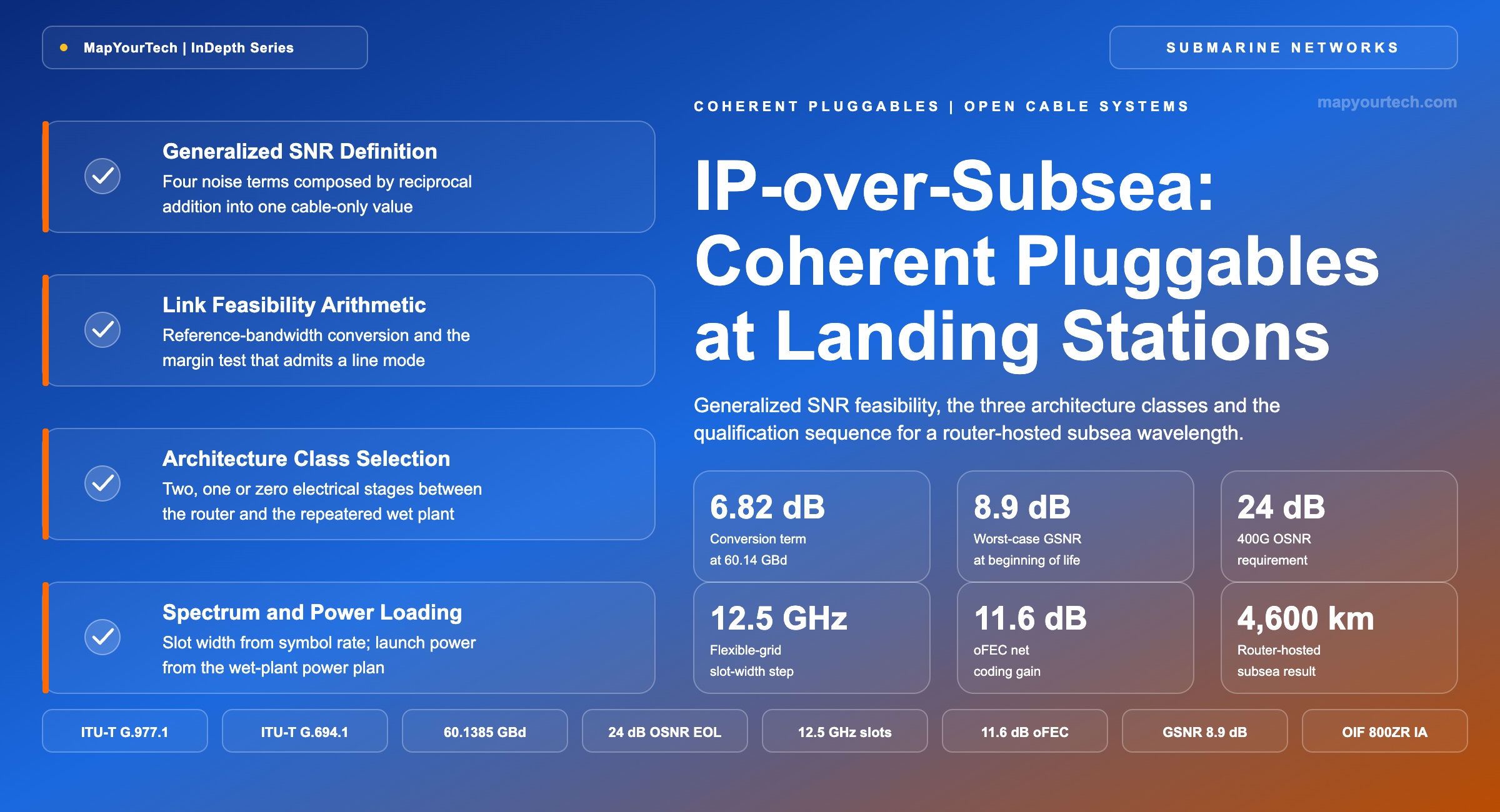
IP-over-Subsea: Coherent Pluggables at Cable Landing Stations
Where the ZR+ pluggable sits, what generalized signal-to-noise ratio it has to clear, and how the three deployable architecture classes differ on a repeatered submarine path.
The control plane knows the route; the physics knows the margin.
What You Will Learn
- Define the generalized signal-to-noise ratio from its four component terms and state it in the reference bandwidth the module operates in (Section 2, Figure 1).
- Place every coherent modem in the system correctly: the wet plant carries no transponder, and both ZR+ terminations sit in the landing stations (Section 3, Figure 2).
- Convert a 24 dB back-to-back OSNR requirement at 60.14 GBd into the 17.2 dB SNR figure that a cable budget is compared against (Section 6, Table 3).
- Quantify why an 8.9 dB beginning-of-life worst-case cable value rules out the 400G 16QAM mode and leaves the QPSK modes at the boundary (Section 6, Figure 4).
- Select between the three architecture classes on measured evidence rather than datasheet reach, using the electrical-stage count and the margin test (Sections 5 and 11, Figure 3).
- Build a slot plan from the 12.5 GHz flexible-grid step, and read the reach penalty of moving a 400G carrier from a 75 GHz to a 112.5 GHz slot (Section 7, Figure 5).
- Run the qualification sequence from measured cable data to a commissioned wavelength, including the flat-transmit acceptance measurement (Section 8, Figure 6).
- Anchor the 2026 roadmap in what is published: 1600ZR and 1600ZR+ implementation agreements, 252 GBd dual-subcarrier operation and 38 to 40 W module targets (Section 12).
1. Introduction
Alcatel Submarine Networks markets a landing-station design under the name IP-over-Subsea, describing it as a combination of ZR+ coherent pluggable technology with high-performance transponders for data-centre-to-data-centre connectivity, associated with pay-as-you-grow capacity activation. That description appears as copy on the company's upgrade page rather than in a dated technical announcement, and it names no module part number, no implementation agreement and no quantified saving. The mechanism underneath it is real and specifiable.
Stripped of the branding, IP-over-subsea places coherent pluggables in routers or thin hosts at the cable landing stations at both ends of a submarine cable, over a wet plant that does not change. No coherent module goes under the sea. The wet plant of a modern repeatered system is passive: fibre pairs, erbium-doped fibre amplifier repeaters, branching units and joints, qualified for a design life of 25 years or more. Every modem in the system has always lived in the dry plant, in the submarine line terminal equipment at the cable landing station. What moves in this architecture is the transponder function, from a dedicated shelf into a router faceplate, and whether it can move is decided optically rather than commercially.
A single quantity decides it. A pluggable specified for 3,000 km over one engineered terrestrial line cannot be assumed to work over a 3,000 km submarine line whose repeater spacing, gain tilt, noise accumulation, filtering, launch power and margin policy are all different. The generalized signal-to-noise ratio the cable delivers on that fibre pair and the signal-to-noise ratio the chosen line mode requires, both stated in the same reference bandwidth, settle it. Everything else in the decision, including power, footprint, spares and the commercial activation model, follows from whether that comparison closes.
The evidence that it can close in some cases is now field evidence rather than laboratory evidence. A 400 Gb/s wavelength at 75 GBd ran across 4,600 km of the Indigo Central submarine cable between Sydney and Perth using ultra-long-haul QSFP-DD pluggables with a 3.2 Tb/s wavelength-division line card, and the same module family covered 3,403 km terrestrially through seven reconfigurable optical add-drop multiplexers and 42 amplifier sites without a standalone transponder or a regeneration point (both vendor claims). Those results move coherent pluggables out of the metro-only category. They do not make every transoceanic wet plant accept a router-hosted carrier at its design rate.
The scope here is repeatered submarine systems operating in the C-band and C+L band, from the router port at one data centre to the router port at the other. Unrepeatered festoon systems, direct-detection systems and the terrestrial backhaul beyond the metro line system fall outside it.
2. Generalized Signal-to-Noise Ratio Definition per ITU-T G.977.1
The generalized signal-to-noise ratio is the ratio of received signal power to the total in-band noise power a submarine path delivers to a coherent receiver, measured in decibels over a stated reference bandwidth. It aggregates amplified spontaneous emission, nonlinear interference and acoustic scattering into one number that describes the cable and no transponder.
Because the composed value belongs to the fibre pair rather than to the equipment at either end, a cable can be measured, accepted, sold in spectrum blocks and later upgraded by a third-party terminal supplier on the strength of one curve of generalized signal-to-noise ratio against frequency. ITU-T G.977.1 defines the reporting format for exactly this purpose on transverse-compatible dense wavelength-division applications over repeatered submarine cable systems, and the same framework carries into the acceptance criteria used for open submarine cable systems.
2.1 Distinctions from the Adjacent Quantities
Four quantities sit next to each other in this arithmetic and are routinely conflated. The ASE-only signal-to-noise ratio counts amplified spontaneous emission from the repeater chain and nothing else; on an interoperable cable budget it is the first row, and it is measured under flat transmit conditions with no attempt to model the transponder. The generalized value adds nonlinear interference, guided acoustic-wave Brillouin scattering and residual terms to that same denominator, so it is always the lower of the two. The optical signal-to-noise ratio is a measurement convention rather than a different physical quantity: it fixes the noise bandwidth at 0.1 nm, roughly 12.5 GHz at 1550 nm, and reports the ratio there regardless of what symbol rate the carrier runs. The effective signal-to-noise ratio then subtracts the transponder's own implementation penalty from the generalized value, which is why two modules quoting the same nominal reach can behave differently on the same fibre pair.
Read the Full Analysis with Premium
The remaining 88% of this article — the design numbers, trade-offs and field guidance — is part of MapYourTech Premium, along with the full premium library, courses and professional tools.
You May Also Like

-
Premium
-
September 1, 2026
-
Free
-
August 31, 2026