Turn-Up, Retune, and Reacquisition Timing in Coherent Interfaces
Four timing cases separate a 40 ms recovery from a 200 s one, and the difference decides whether an optical protection switch meets its objective.
In optical networks, failure is not an option, it's a scenario to be managed.
1. Introduction
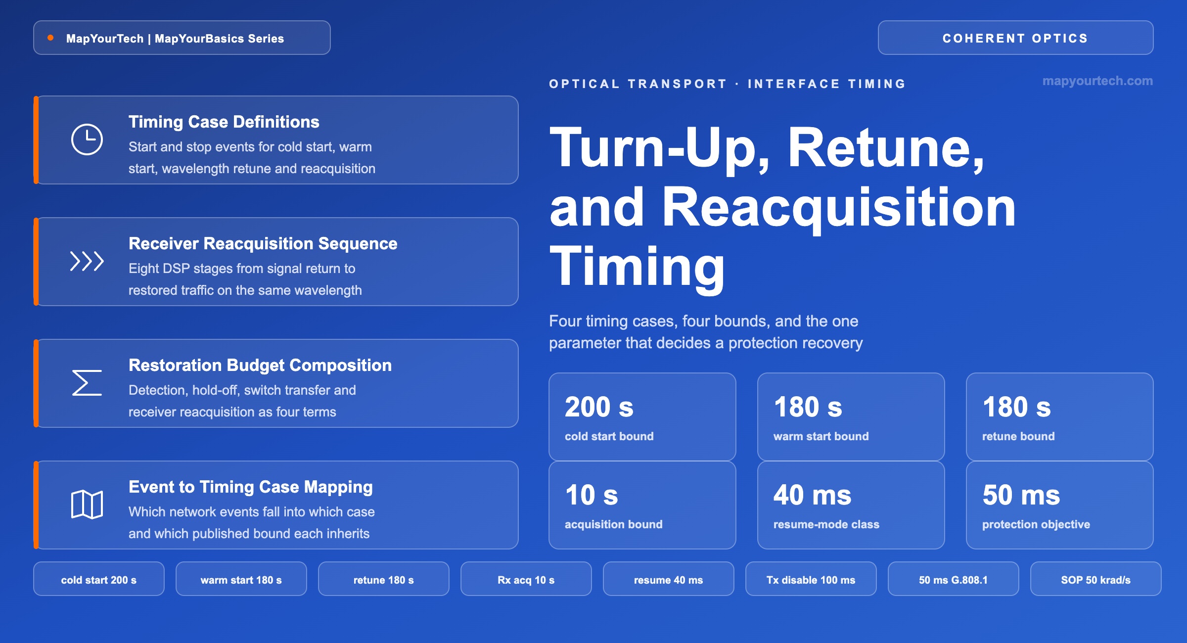
A coherent line interface takes between 40 ms and 200 s to start carrying traffic, and which end of that range applies depends entirely on what happened to it. The OIF 800ZR Implementation Agreement allows a module up to 200 s from reset de-assertion to the DataPathActivated state, and up to 180 s to change transmitter wavelength including turn-up (both standard-specified). The same document allows only 10 s for the receiver to acquire a signal after Rx_LOS de-asserts when the data path is already active (standard-specified), and a published specification for a C+L-band flexrate coherent module states 40 ms for the same recovery when the receiver runs in a resume mode with a bounded dispersion search (vendor claim). Four orders of magnitude separate the fastest published bound from the slowest, and the parameter that selects between them is not the module part number.
A frequent design error follows from reading the wrong figure. A protection scheme specified against a 50 ms objective is checked against the transceiver turn-up time, and optical-layer protection is then ruled out for the coherent layer. Turn-up is measured from a module holding no link state: the laser is thermally unsettled, the modulator bias is unoptimized, and the receiver holds no dispersion, polarization or phase estimate. Reacquisition is measured from a module already provisioned, already tuned, and holding converged equalizer state from before the event. The two figures share a signal path and share no initial conditions.
Four cases are separated here: cold start from reset, warm start from a low-power or transmitter-off condition, wavelength retune to a new frequency, and receiver reacquisition after the signal returns on the same frequency. Each is defined by its start and stop event, bounded by a standard-specified figure where one exists, and mapped onto the network events that trigger it. The scope is single-carrier coherent line interfaces with soft-decision forward error correction (FEC), managed through the Common Management Interface Specification (CMIS), whether packaged as a pluggable in a router port or as an embedded line module. The wider context of that port sits in the IP-over-DWDM architecture walkthrough.
Takeaway: Turn-up time and reacquisition time answer different questions. A recovery design that quotes the turn-up figure will over-estimate restoration time by two to three orders of magnitude and will discard workable protection schemes.
2. Timing Interval Definition and Endpoint Events
A coherent interface timing interval is the elapsed time between two named module events, the first of which starts the interval and the second of which ends it. The interval is measured in milliseconds or seconds and is a property of the event pair, not of the module, so changing either endpoint changes the figure without changing hardware.
Four adjacent quantities are routinely conflated with each other and with the interval above, and each has its own endpoint pair. Turn-up time starts at a module event — reset de-assertion or a low-power exit — and ends at DataPathActivated, so it includes laser thermal settling and modulator bias optimization. Reacquisition time starts when the optical signal returns at the receiver and ends when traffic passes, with the module already provisioned and tuned. Protection switching time covers the optical switch transfer and any protocol exchange, and ends when the standby path is connected, not when traffic is carried. Restoration time spans the whole event from the failure to traffic returning and therefore contains all of the others. Hold-off time is a configured delay inside the restoration interval, not a property of any equipment.
The arithmetic is additive within one interval and needs no unit conversion beyond the decimal one:
Interval Arithmetic
T_restore = T_detect + T_holdoff + T_switch + T_reacq [ms], T[s] = T[ms] / 1000
Where:
- T_detect — signal-loss detection and defect persistency, in ms.
- T_holdoff — configured delay before the protection controller acts, in ms.
- T_switch — optical switch transfer and protocol exchange, in ms.
- T_reacq — receiver reacquisition from signal presence to traffic, in ms.
Applying the arithmetic to the 1+1 protected pair of Figure 1: detection and persistency take 8 ms, hold-off is 0 ms because no lower layer recovers first, the switch transfers in 12 ms, and the receiver reacquires in 40 ms with a bounded dispersion search. The interval is 8 + 0 + 12 + 40 = 60 ms, against a 50 ms objective. The same pair with an unbounded search replaces the last term with the standard-specified 10 s bound and the interval becomes 10.02 s. Section 5.3 carries this case through in full.
Takeaway: An interval is defined by its two endpoint events, and the four terms above have four different endpoint pairs. A figure quoted without them can be off by a factor of 200 on identical hardware.
3. Related Work
The terminology used here comes from three sources: the CMIS management specifications, the ZR-class implementation agreements, and the ITU-T protection recommendations. CMIS defines the module state machine and the Data Path State Machine (DPSM), which together govern how a module moves from reset through provisioning to an activated data path; the module state machine allows 2 s for management initialization and advertises its other durations to the host (standard-specified). CMIS 5.1 added the Network Path State Machine (NPSM), which lets the media side be brought up independently of the host side and which largely mirrors the DPSM in structure. That separation matters for timing work, because the slow part of a coherent turn-up is on the media side while the host electrical side is comparatively immediate.
The OIF Implementation Agreement for Coherent CMIS (C-CMIS) extends the base specification with coherent-specific pages, diagnostics and monitors, and is where a host reads the signal-quality and optical-link performance observables that indicate how far an acquisition has progressed. OIF continues to develop management supplements in this area, including an autonomous path startup extension covering host-side and media-side link training. The interface-level timing numbers themselves live in the ZR-class implementation agreements; the 800ZR document states them as informative module requirements, and its companion generation is covered in the 800ZR and 800ZR+ overview.
On the network side, ITU-T G.808.1 and G.873.1 define linear protection switching and the 50 ms switching objective that transport designs are written against, together with the signal-fail persistency filtering that precedes any switch: G.873.1 recommends a verification interval of no more than 10 ms before a signal-fail condition is reported to the protection controller (standard-specified). The relationship between that objective and the layers above it is treated in the 50 ms protection switching reference and in the broader availability design article.
Burst-mode coherent reception work bounds the contribution of the digital signal processing (DSP) itself, which is not what sets the second-scale figures. Equalizer acquisition in sub-microsecond time has been reported in back-to-back experimental systems using efficient equalizer initialization (measured, laboratory conditions). What consumes time in a deployed link is the search over unknown parameters, principally accumulated chromatic dispersion, and commercial coherent interfaces expose configurable minimum and maximum dispersion search bounds precisely so that this search can be constrained by the operator.
Takeaway: The state machines come from CMIS and C-CMIS, the timing bounds from the ZR-class implementation agreements, and the 50 ms target from ITU-T G.808.1 and G.873.1. No single document holds all three, which is why the four cases are routinely conflated.
4. Timing Case Definitions and Measurement Conditions
Each of the four cases applies the interval definition of Section 2 to a specific pair of CMIS state events. Naming both endpoints in CMIS terms lets a host implementation and a datasheet be compared directly.
4.1 Start and Stop Events
Cold start runs from de-assertion of the module reset signal to DataPathActivated, with the low-power request already cleared. It includes power rail sequencing, management initialization, laser thermal stabilization, modulator bias optimization and any tunable filter alignment. Warm start runs from ModuleLowPwr to DataPathActivated and covers ModulePwrUp, data path initialization and the transmitter turn-on state; the laser is already thermally settled, which is the entire reason the two figures differ.
Wavelength retune runs from the tuning command to a module tuned, turned up and stable on the new frequency, including modulator bias re-optimization and any tunable filter and variable optical attenuator control loop. Receiver reacquisition runs from Rx_LOS de-assertion to a signal acquired and traffic passing, with the data path already in DataPathActivated. Only the last of these is a candidate for a protection-class recovery, because only the last one starts from a module whose transmitter, laser, bias and filter state are all already correct.
4.2 Conditions Attached to a Reacquisition Figure
Published reacquisition figures are conditional on six parameters. Each condition below is stated in the source specification alongside the figure, and each has a physical basis in the acquisition process.
- Symbol rate and modulation format. Equalizer and carrier-recovery convergence scale with symbol count, so a figure quoted at one baud rate does not transfer to another. The published 40 ms class figure is stated at 69 GBd (vendor claim).
- Dispersion search range. The published figure applies to a search under 30,000 ps/nm (vendor claim). A wider blind search costs time in direct proportion to the number of hypotheses tested.
- Polarization dependent loss (PDL) and differential group delay (DGD). Stated at 3 dB and 30 ps respectively for the fast case (vendor claim); beyond those the adaptive equalizer needs more symbols to separate the polarizations.
- State of polarization slew rate. Stated at 1 rad/ms for the fast reacquisition case (vendor claim). Separately, OIF 800ZR requires tolerance to 50 krad/s of polarization change in steady-state operation (standard-specified) — a switch event that exceeds the tracking rate forces reacquisition rather than a ride-through.
- Received power and its slew rate. OIF 800ZR specifies tolerance to a ±2 dB input power transient with 20% to 80% rise and fall times no faster than 50 µs, equivalent to a maximum slew of 24 mdB/µs (standard-specified). A protection switch that lands the receiver outside its input power range starts a new acquisition instead of riding through.
- Same transmitter before and after. The fast case assumes the signal comes from the same transmitter to the same receiver across the event. A different far-end transmitter invalidates the stored state and the resume mode has to be restarted (vendor claim).
These conditions are also the test conditions. Any laboratory verification of a reacquisition figure has to reproduce them, which places the measurement squarely in the domain covered by coherent transponder test and measurement practice: a calibrated polarization scrambler, a dispersion emulator set to the path value, and a switch under test with a characterized loss step.
Takeaway: Record the six conditions alongside every reacquisition figure. The same module returns tens of milliseconds or tens of seconds depending on those six values, so a figure carried into a design without them is unbounded in practice.
5. Results and Discussion
The published bounds fall into two clusters separated by roughly four orders of magnitude. Transmitter disable and bounded reacquisition sit in the tens of milliseconds; every process involving the laser, the modulator bias or the tunable filter sits in the tens to hundreds of seconds. The protection decision falls on the boundary between the two.
5.1 Timing Envelopes Across the Four Cases
| Case | Reference points | Standard-specified | Vendor claim |
|---|---|---|---|
| Transmitter disable | Output-disable command to output below the transmitter-off level | 1–100 ms | ≤ 10 ms |
| Receiver reacquisition | Rx_LOS de-assert to signal acquired, data path already active | ≤ 10 s | 40 ms, resume mode |
| Warm start | ModuleLowPwr to DataPathActivated | ≤ 180 s | ≤ 5 s |
| Wavelength retune | Tuning command to tuned, turned up and stable | ≤ 180 s | ≤ 90 s |
| Cold start, transmitter | Reset de-assert to DataPathActivated | ≤ 200 s | 75–120 s |
| Cold start, receiver | Module reset to signal fully acquired | ≤ 200 s | 60–120 s |
| Optimization convergence | Valid input signal to converged receiver optimization | not specified | ≤ 120 s |
The standard-specified column is drawn from the OIF 800ZR module requirements, which are stated as maxima an interoperable implementation must not exceed. The vendor-claim column is drawn from the published specification of a C+L-band flexrate coherent module and shows what a shipping implementation states for the same events. The gap between the two columns in the warm-start row — 180 s against 5 s — is the clearest illustration that these standard bounds are conformance envelopes rather than expected behaviour, and a design that treats them as expected behaviour will size every maintenance window wrongly.
Takeaway: A recovery targeting the 50 ms objective class has to be met from the first cluster. No configuration parameter moves a laser, modulator-bias or tunable-filter process into it, so the case selection is made by the network event and not by the module.
5.2 Receiver Reacquisition Sequence
Reacquisition proceeds through a fixed sequence of DSP stages, and only one of them has a duration that varies by orders of magnitude with configuration. Automatic gain control and receiver attenuator settling, frequency-offset estimation, adaptive equalization, carrier phase recovery and FEC decoder convergence are all bounded by symbol counts, and at tens of gigabaud a symbol count in the millions is still under a millisecond. Chromatic dispersion estimation is the exception, because a blind estimator has to test hypotheses across the whole configured search window before the equalizer can converge on any of them.
The dispersion search window is a provisioned parameter, so the control plane sets it directly. A path whose accumulated dispersion is known — and it is known, because the receiver reports the dispersion it is compensating to within ±3% or ±100 ps/nm, whichever is larger (vendor claim) — can have its search window narrowed to a band around the expected value before the signal returns. For a protection pair, the working and standby paths have different lengths and therefore different accumulated dispersion, so the standby value is the one that must be preloaded. The dispersion contribution of each candidate path follows directly from the fiber and its length, a calculation set out in the ITU grid and channel spacing reference for the frequency side and in ordinary span arithmetic for the length side.
The published resume mode is the productized form of this idea: the receiver retains its converged state across the outage and re-enters from it rather than from a blank start. Its stated confidence is above 99%, with the residual not a convergence failure but a longer recovery (vendor claim) — which means a protection design should carry a second-order case where the switch takes longer than the objective and the higher layer absorbs it. That behaviour is the multi-layer coordination case described in the IPoDWDM fundamentals article.
Takeaway: Bound the dispersion search window per path and the reacquisition time collapses from seconds to tens of milliseconds. Leave it at the full range and no amount of DSP capability recovers the difference.
5.3 Protection Restoration Budget Composition
End-to-end restoration time is the sum of four terms, of which the coherent receiver contributes one. The composition below identifies which term the interface influences and which terms are set elsewhere in the network.
Restoration Time Composition
T_restore = T_detect + T_holdoff + T_switch + T_reacq
Where:
- T_detect — loss-of-signal detection and defect persistency; ITU-T G.873.1 recommends a verification interval of no more than 10 ms. Typical range 1–10 ms.
- T_holdoff — configured hold-off before the protection controller acts, used to let a lower layer recover first. Typical range 0–100 ms, set to 0 for single-layer optical protection.
- T_switch — optical switch transfer and, where used, automatic protection switching protocol exchange. Typical range 1–20 ms depending on switch technology.
- T_reacq — receiver reacquisition from signal presence to traffic. 40 ms class in bounded resume mode, up to 10 s under the standard-specified blind bound.
Practical Example — restoration budget on a 1+1 protected line
Take a protected pair where the working and standby fibers differ by 60 km of G.652 fiber, both carrying the same transmitter's wavelength through an optical line protection switch. Loss-of-signal detection and persistency consume 8 ms, hold-off is set to zero because no lower layer exists to recover first, and the switch transfers in 12 ms. That leaves 30 ms of the 50 ms objective for the receiver.
With the dispersion search window preloaded for the standby path, a 40 ms class reacquisition puts the total at 60 ms — over the objective, but within the same order, and the FEC holds through part of the transient so the observed traffic hit is shorter than the arithmetic suggests. With the search window left at its default full range, the standard-specified bound of 10 s applies and the total is 10.02 s, which is 200 times the objective and is a service outage rather than a protection event. The two designs use identical hardware. The difference is one configured parameter per path.
The 60 km length difference is itself the reason the preload has to be per-path: at roughly 17 ps/(nm·km) the two paths differ by about 1,020 ps/nm of accumulated dispersion, enough to place the standby path outside a window centred tightly on the working path.
Takeaway: A coherent interface influences one of the four terms. When that term is bounded it is comparable to the switch transfer time; when it is not, it dominates the budget by two orders of magnitude and no other term matters.
5.4 Network Event to Timing Case Mapping
Two properties of a network event determine which timing case applies: whether the far-end transmitter changes across the event, and whether the optical frequency changes. The mapping is deterministic once both are stated, and Figure 5 gives it for the five events that occur most often in service.
Two consequences follow for network design. First, mesh restoration that re-routes a service onto a different wavelength cannot be a protection-class mechanism at the optical layer, because it inherits the retune bound of up to 180 s (standard-specified) regardless of how quickly the control plane computes the new route. Restoration and protection are different mechanisms with different time constants, a distinction developed in the route and regeneration planning article. Second, a maintenance procedure that reseats a module commits to the cold-start bound, so a rolling upgrade across a protected pair has to complete and verify one side before touching the other.
Loss-of-signal detection and the received-power alarm are separate observables with separate latencies. A published specification states up to 150 ms between loss of signal and the receiver power alarm on complete input power loss (vendor claim), so a recovery time measured from an alarm timestamp carries that offset and over-reports against the signal event. Field measurements should be corrected for it before comparison with a datasheet figure. Alarm behaviour and its correlation across layers is covered in the OTN alarms troubleshooting guide and in the operational metrics article.
Takeaway: Same transmitter and same frequency gives the reacquisition case and a protection-class recovery. A new frequency gives the retune case at up to 180 s. Removed module state gives the cold-start case at up to 200 s.
6. Conclusion
Coherent interface timing resolves into four bounds rather than one. Cold start and wavelength retune are laser and modulator processes bounded at 200 s and 180 s respectively by the OIF 800ZR module requirements (standard-specified). Warm start removes the thermal settling and is bounded at 180 s by the same document, while a shipping implementation states 5 s for it (vendor claim). Receiver reacquisition, the only case that starts from a module already provisioned and already tuned, is bounded at 10 s in the standard and stated at 40 ms in a resume mode with a bounded dispersion search (vendor claim).
That last pair of figures carries the design consequence. Optical protection at the coherent layer meets a 50 ms class objective only when the receiver reacquisition is bounded, which requires the dispersion search window to be configured per path rather than left at its default range, and requires the working and standby paths to present the same transmitter, a received power step inside the specified transient tolerance, and a polarization slew inside the tracked rate. Each of those is a provisioning choice rather than a hardware capability, and each parameter is exposed through the management interface. Configuring them converts a 10 s conformance bound into a 40 ms operational figure on the same hardware.
Two items in current standards work bear on these figures. Management supplements now under development in OIF address autonomous path startup and link training, which move more of the turn-up sequence into defined, observable states rather than vendor-internal behaviour. And as line interfaces move to higher symbol rates and wider bands, the dispersion search space grows with the spectrum being covered, which increases rather than reduces the value of a control plane that tells the receiver where to look.
7. References
- Optical Internetworking Forum, Implementation Agreement 800ZR (OIF-800ZR), Optical Internetworking Forum.
- Optical Internetworking Forum, Common Management Interface Specification (CMIS), Optical Internetworking Forum.
- Optical Internetworking Forum, Implementation Agreement for Coherent CMIS (C-CMIS), Optical Internetworking Forum.
- ITU-T, Recommendation G.873.1 — Optical Transport Network: Linear Protection, ITU-T Study Group 15.
- ITU-T, Recommendation G.808.1 — Generic Protection Switching: Linear Trail and Subnetwork Protection, ITU-T Study Group 15.
Sanjay Yadav, "Optical Network Communications: An Engineer's Perspective" — Bridge the Gap Between Theory and Practice in Optical Networking.
Related Articles on MapYourTech