
Regeneration Placement on Threshold-Limited Optical Routes
Segment decoupling as the design tool when one span dominates the noise budget: the arithmetic that locates a regeneration site, the two ceilings that bound what it returns, and why a regenerator repairs the cascade but never the failing span itself.
1. Introduction
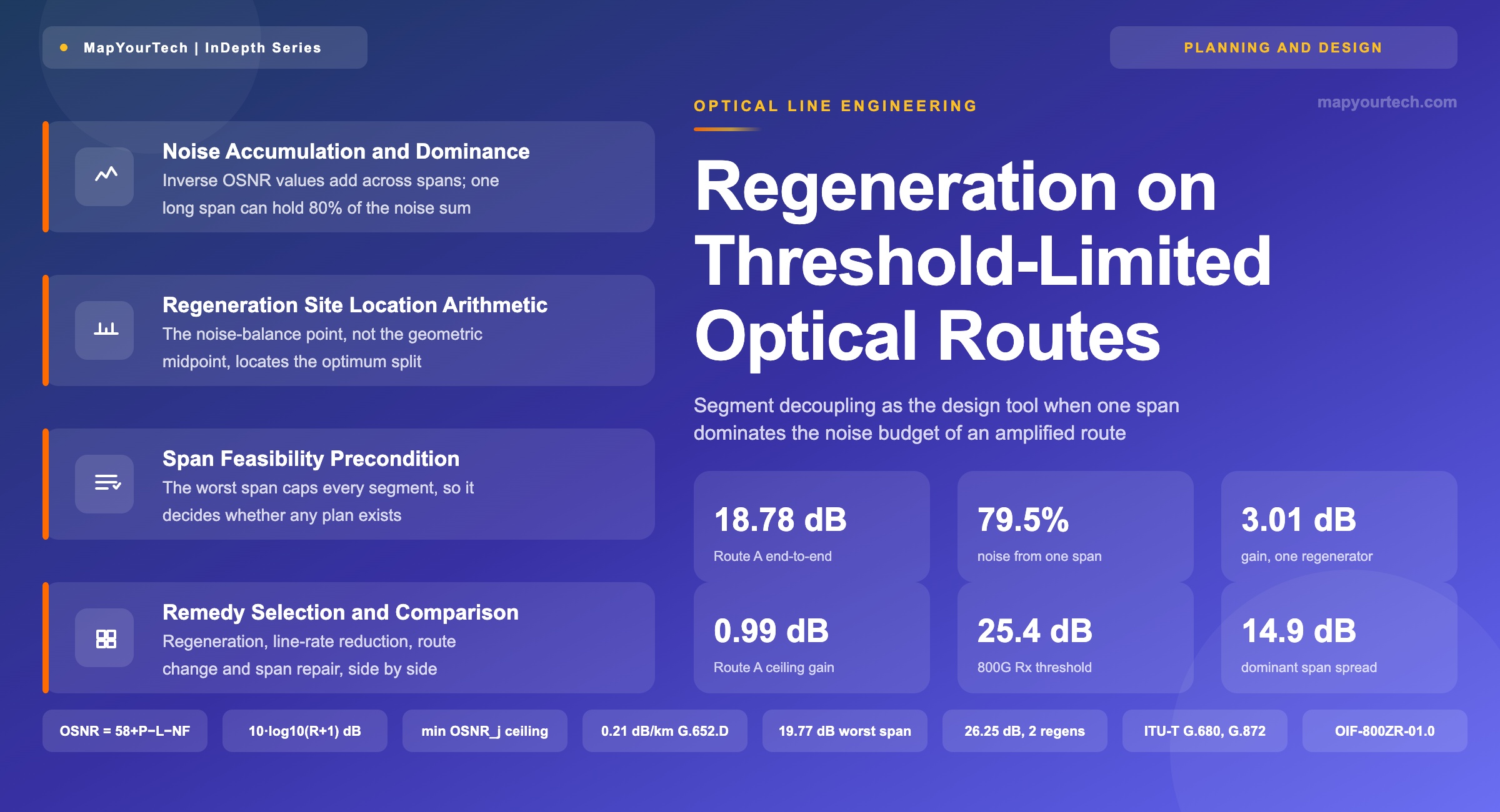
A 142 km fiber crossing between two amplifier huts on an otherwise ordinary 862 km terrestrial route presents 31.7 dB of span loss. With 0 dBm of launch power per channel and a dual-stage amplifier holding 6.5 dB of noise figure at that gain, the span delivers 19.77 dB of optical signal-to-noise ratio (OSNR) on its own. The other eight spans on the route are 80 km each, present 17.8 dB, and deliver 34.70 dB apiece. Summed as noise powers, the nine spans give 18.78 dB at the receiver, and the single long crossing accounts for 79.55 percent of the accumulated amplified spontaneous emission (ASE). Every one of these values is computed from the span inventory using the standard per-span form; none is measured, and Section 3 states the arithmetic in full.
The planning request that follows is narrow and common: the route will not close at 800G, so a regeneration site is wanted. On this route no regenerator placement closes it, and the reason is worth more than the answer. A 3R regeneration site partitions the optical path into two independent noise budgets. It resets accumulated ASE, accumulated nonlinear interference, residual chromatic dispersion, and the filter narrowing built up through a reconfigurable optical add/drop multiplexer (ROADM) cascade. What it cannot do is change the loss or the noise figure of any span. The 142 km crossing sits inside whichever segment contains it, and that segment inherits its 19.77 dB. Against an 800G 16QAM-class receiver threshold of 25.4 dB, taken from a current coherent line-module datasheet, the segment fails whatever else is done to the route.
That observation generalizes into a test that costs one line of arithmetic and should run before any placement search: compare the minimum per-span OSNR on the route against the receiver threshold plus system margin. If the worst span fails on its own, regeneration is not the remedy, and the design has to move to a lower line rate, a physical repair of the dominant span, or a different route. Running the placement optimizer first produces a plausible-looking site, a bill of materials, and a link budget that still does not close.
Segment decoupling is a genuine design tool, and the rest of this article treats it as one. On a route where the per-span OSNR values are similar, one regenerator placed at the noise-balance point buys exactly 10·log10(2) = 3.01 dB, independent of how many spans the route carries. Two regenerators buy 4.77 dB. The gain follows 10·log10(R+1) for R regenerators on a uniform route, which is a combinatorial result and not a physical one — it comes from splitting a sum of equal terms into equal parts. On a route with one dominant span the same partition returns far less, because the dominant term cannot be split. Route A above gains 0.46 dB from one regenerator and 0.99 dB from two, then nothing at all from a third.
The two ceilings interact in a way that decides most real cases. The combinatorial ceiling says how much a partition can win when the noise is spread evenly. The worst-span ceiling says the delivered OSNR can never exceed the OSNR of the worst individual span, because that span belongs to some segment and caps it. A route is a good candidate for regeneration when it is long and even, and a poor one when it is short and lopsided. The lopsided case is the one that generates escalations, because the total distance looks modest, the reach table says the line rate should work, and the route fails anyway.
This article works the full decision. Section 2 traces how translucent design displaced both fully opaque and fully transparent architectures, and why the regenerator became a placement variable rather than a fixed per-span element. Section 3 derives the reciprocal noise sum and defines the dominant-span condition quantitatively. Section 4 covers the three node implementations that perform the 3R function and what each one does to the segment boundary. Section 5 gives the placement arithmetic, including the noise-balance rule that locates the optimum site and the feasibility precondition that decides whether a site exists. Section 6 turns that into a step-by-step design procedure. Sections 7 through 9 compare regeneration against the two alternatives — lower line rate and route change — on delivered OSNR, capacity, latency, and capital. Sections 10 and 11 cover the limits of the method and the open problems. Readers who want the underlying noise arithmetic first will find it developed in the MapYourTech treatment of OSNR fundamentals and the 58 dB reference constant.
All span geometries, losses, and OSNR values in the worked routes are computed from stated inputs, not measured. Receiver OSNR thresholds are quoted from coherent line-module datasheets and are labeled as vendor specification where they appear. Standard-specified values carry their recommendation number. The three routes — A, B, and C — are constructed to isolate specific behaviors and are not descriptions of any deployed network.
1.1 Definitions
Threshold-limited route. A route where the delivered OSNR or generalized signal-to-noise ratio (GSNR) sits below the receiver threshold plus the system margin the design rules require, so the service will not turn up at the requested line rate.
Dominant span. A span whose inverse-OSNR term exceeds the sum of all other spans' inverse-OSNR terms on the same path. Section 3.3 makes this precise and shows what separation in decibels the condition implies.
Segment. The set of consecutive spans between two 3R points, where the endpoints may be the service terminations or intermediate regenerators. Each segment has its own independent noise budget.
Segment decoupling. The design action of inserting a 3R point so that the noise accumulation of one part of a path no longer adds to the noise accumulation of another. This is the only thing a regenerator does to the physical layer, and naming it precisely is what keeps the analysis honest.
2. Historical Development of Translucent Network Design
Regeneration was not always a placement decision. In the first generation of wavelength-division multiplexed (WDM) long-haul systems, every intermediate node terminated every wavelength electrically. A signal entering a node was converted to electrical form, retimed and reshaped, and launched again on a new optical carrier. The architecture was fully opaque, and the number of optical-electrical-optical (O-E-O) conversions on a path equaled the number of intermediate nodes. Reach engineering was a minor discipline because the optical path between conversions was one span or a small handful of spans, and the noise budget almost never bound.
What made this workable was the cost structure of the time. The transponders were direct-detection devices with modest optical performance, and the electrical bridging equipment at each node was a substantial but accepted line item. What made it unworkable was scale. When per-fiber channel counts reached 40 and then 80, the transponder count at a transit node rose in direct proportion, and the transit traffic — wavelengths that entered and left without any local add or drop — consumed the majority of that count. The industry response was the optical bypass element: first the fixed optical add/drop multiplexer, then the wavelength-selective-switch ROADM, which lets a wavelength cross a node in the optical domain and reserves the transponder shelf for traffic terminating at that node.
2.1 Fully Transparent Architectures and Path-Dependent Failure
Optical bypass invited the opposite extreme. A wavelength that can cross one node optically can in principle cross every node on its path optically. A fully transparent network places no O-E-O conversion between the source and the destination transponders, and the resulting capital saving is large. It also makes the physical layer the binding constraint on connectivity, and it makes that constraint non-local. Whether a connection can be established now depends on the accumulated impairments of every span, node, and filter along its specific path.
Three impairments accumulate along an optically transparent path, and the design has to budget all three. ASE noise from each line amplifier adds as a power, which is what produces the reciprocal sum in Section 3. Nonlinear interference generated in each span through the Kerr effect also adds, span by span, and its magnitude depends on the launch power the design chose to buy OSNR with — a coupling that makes the two budgets inseparable. Filter narrowing from each ROADM's wavelength-selective switch (WSS) passband compounds multiplicatively; the effective passband after a cascade of ROADMs is narrower than any single stage, and a signal whose spectrum was comfortably inside the slot at the source can be clipped at the destination. The general framework for accumulating these effects across network elements is set out in ITU-T Recommendation G.680, which defines physical transfer functions for optical network elements, and the engineering considerations for applying it are collected in ITU-T Supplement G.Sup39.
Read the Full Analysis with Premium
The remaining 88% of this article — the design numbers, trade-offs and field guidance — is part of MapYourTech Premium, along with the full premium library, courses and professional tools.
You May Also Like

-
Free
-
September 4, 2026

-
Premium
-
September 4, 2026

-
Premium
-
September 4, 2026