
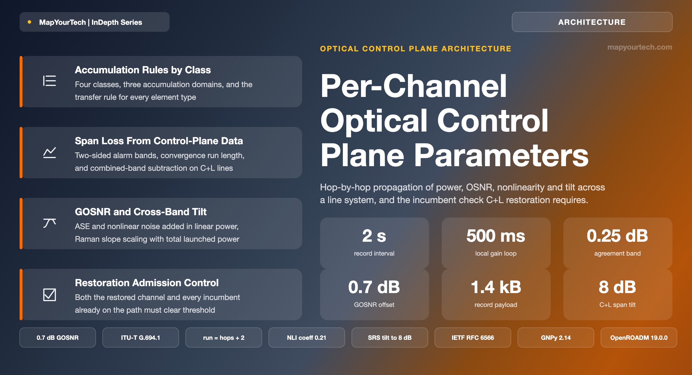
Per-Channel Parameters in Embedded Optical Control Planes
How a modern line system propagates per-channel power, OSNR, accumulated nonlinearity, dispersion, PMD and tilt hop by hop, computes span loss from control-plane data alone, and why restoration logic must evaluate GOSNR impact — including cross-band stimulated Raman scattering — before it moves a channel.
1. Introduction
An in-line amplifier sitting in a roadside hut 90 km from the nearest staffed site has to decide, every few hundred milliseconds, how much gain and how much tilt to apply. It has one photodiode reading total input power, one reading total output power, and no direct measurement of any individual channel. It does not know how many channels are present, what baud rate they run, how much dispersion they have already accumulated, or how close the weakest one is to its forward error correction (FEC) threshold. Every one of those facts lives somewhere else in the network — at the transponder that launched the channel, at the reconfigurable optical add-drop multiplexer (ROADM) that switched it, at the amplifier one span upstream.
The mechanism that closes that gap is a per-channel parameter record: a compact data structure generated where a channel enters the optical layer, transmitted between adjacent ports on the optical supervisory channel (OSC), and rewritten at every element the light passes through. Each element reads the record from its input port, applies a transfer rule specific to its own function — a fiber span adds dispersion and nonlinear noise, an amplifier adds amplified spontaneous emission (ASE) and gain, a wavelength selective switch (WSS) adds insertion loss and a hop count — and transmits the updated record from its output port. By the time the record reaches the far-end ROADM, it carries a per-channel description of everything that happened to the light along the way, assembled without a single end-to-end measurement.
This is not telemetry in the usual sense. Telemetry reports what a device measured. A parameter record reports what the network computed, incrementally, using measurements taken at the only points where measurement is cheap: total power at an amplifier port, per-channel power at an optical channel monitor (OCM), and configured span properties. The distinction matters operationally. Per-channel optical signal-to-noise ratio (OSNR) at an in-line site would otherwise require an optical spectrum analyser at every hut. Accumulated nonlinear interference has no direct measurement at all — it can only be computed from launch power, fiber type, effective length and symbol rate. Accumulated chromatic dispersion is knowable only from the sum of span lengths and dispersion coefficients along the actual switched path, which the element itself does not know.
Three functions depend on this record, and each fails in a distinct way without it. Automatic power control needs the channel count and the target per-channel power to set amplifier gain and the variable optical attenuator (VOA) that follows it; without the record, the amplifier can hold total output power but cannot hold per-channel power as loading changes. Fault localisation needs the transmitted total power from the upstream port to compute span loss by subtraction; without the record, an operator learns that a receiver lost margin but not which span degraded. Impairment-aware restoration needs per-channel generalised OSNR (GOSNR) on every candidate path; without it, the control plane can compute a topologically valid detour that the transponder cannot receive.
The third case is where the design pressure now sits. A control plane that restores on hop count or kilometres alone was adequate when every channel ran the same fixed-grid 10 Gb/s format. It is not adequate for a flexible-grid line carrying 400 Gb/s and 800 Gb/s channels at three different baud rates with three different OSNR thresholds, and it becomes actively unsafe on a C+L band system, where moving spectrum changes the total launched power and therefore changes the stimulated Raman scattering (SRS) tilt experienced by every other channel on the fiber — including channels in the other band that the restoration was never supposed to touch.
This article works through the mechanism end to end. Section 3 sets out what a per-channel record contains and why each field is in it. Section 4 covers transport, cadence and the layering between the embedded record, the node controller and the domain controller. Section 5 derives the span-loss and GOSNR arithmetic, including the SRS corrections that make span loss on a heavily loaded fiber differ from the value a naive subtraction returns. Section 6 covers the convergence logic that keeps a noisy measurement from raising a false span-loss alarm. Sections 8 to 10 cover field behaviour, the comparison against controller-computed and digital-twin approaches, and the boundaries where the embedded model stops being sufficient.
Throughout, the values quoted are labelled by evidence class. Standard-specified values come from ITU-T, IETF or multi-source agreement (MSA) documents and are cited as such. Design-practice values are the ranges and granularities used in deployed embedded implementations. Illustrative values are worked examples constructed to show the arithmetic, not measurements from any particular network. Readers who want the underlying physics before the control mechanics should start with OSNR fundamentals and the Gaussian Noise model for optical transmission, which supply the noise accumulation and nonlinear interference results used from Section 5 onward.
Takeaway: A per-channel record turns a chain of elements that each see only total power into a distributed computation of per-channel state. The record is not a measurement report — it is an incremental calculation carried alongside the light, and its accuracy is bounded by the transfer rules each element applies rather than by any single instrument.
2. Development of Impairment-Aware Optical Control
2.1 Opaque Networks and the Absence of Accumulation
Before optical bypass, the question this article addresses did not exist. Every wavelength was received electrically at every node, so impairments never accumulated across more than one span sequence. Routing was a topological problem: find a path with a free wavelength and enough regenerators. The physical layer supplied a binary answer — the span either closed or it did not — and the answer was fixed at design time by the link budget, not evaluated at connection setup.
The generalized multi-protocol label switching (GMPLS) architecture defined in IETF RFC 3945 inherited that assumption. Traffic engineering extensions to the interior gateway protocols, in RFC 3630 for OSPF and the equivalent for IS-IS, carried bandwidth, administrative colour and shared risk link group (SRLG) membership. None of them carried an impairment. The routing database described what the network was connected to, not what the light would look like when it arrived.
2.2 Transparency and the Impairment Problem
Optical bypass changed the economics and broke the abstraction. A channel that crosses four ROADMs without electrical regeneration accumulates ASE from every amplifier, dispersion from every kilometre of fiber, polarisation mode dispersion (PMD) from the fiber and the passive components, polarisation dependent loss (PDL) from every WSS and coupler, and nonlinear interference from the Kerr effect acting across the whole path. Whether the connection works depends on the sum, and the sum depends on which path the control plane selects.
The IETF response arrived as a framework rather than a protocol. RFC 6163 established the framework for GMPLS and path computation element (PCE) control of wavelength switched optical networks (WSON), and RFC 6566 extended it to networks where impairments cannot be ignored. Both documents are explicit that the impairment information has to come from somewhere, and both stop short of specifying how a network element obtains a per-channel OSNR it never measured. That gap is where embedded parameter records were built.
ITU-T approached the same problem from the equipment side. Recommendation G.680 defines physical transfer functions of optical network elements — the per-element rules by which an impairment entering a network element relates to the impairment leaving it. Read as a control-plane document rather than a design document, G.680 is precisely a specification of transfer rules for accumulated parameters. Recommendation G.697 defines optical monitoring for DWDM systems and is deliberately non-prescriptive about which parameter must be monitored where, on the reasoning that a blanket monitoring requirement produces a costly and sub-optimal design. That reasoning is the argument for computation over measurement, made in a standards document two decades ago.
2.3 Vendor-Internal Records and the Move to Open Models
Through the 2000s and 2010s, the practical implementations were vendor-internal. Each line system defined its own record format, its own field set and its own transfer rules, transmitted over its own supervisory channel encapsulation. The records were never exposed to the operator; they surfaced only indirectly, as an amplifier that held per-channel power correctly, a span-loss alarm that pointed at the right hut, and a restoration engine that declined an infeasible path. Interoperability was not a design goal, because the line system between two ROADMs came from one supplier.
Disaggregation removed that assumption. Once a transponder from one supplier launches into an open line system from another, the per-channel parameters have to cross a documented boundary. Three model families now carry that traffic. OpenROADM defines device, network and service models plus optical specifications for the single-wavelength and multi-wavelength interfaces; the MSA published release 19.0.0 in May 2026, following release 18.1.0 in January 2026 and optical specifications version 9.0.0 in November 2025 (standard-specified, per the MSA public repository). OpenConfig defines transponder-centric models, including openconfig-terminal-device-properties, which carries per-mode minimum receiver OSNR, maximum accumulated chromatic dispersion, maximum differential group delay and the corresponding penalty curves. The IETF work on optical impairment-aware topology, carried in draft-ietf-ccamp-optical-impairment-topology-yang, reached revision 24 in June 2026, has cleared IETF Last Call and sits in IESG evaluation, and remains formally a work in progress; it augments the traffic engineering topology model of RFC 8795 with read-only per-link impairment data for path computation.
Read the Full Analysis with Premium
The remaining 88% of this article — the design numbers, trade-offs and field guidance — is part of MapYourTech Premium, along with the full premium library, courses and professional tools.
You May Also Like

-
Free
-
September 4, 2026

-
Premium
-
September 4, 2026

-
Premium
-
September 4, 2026