
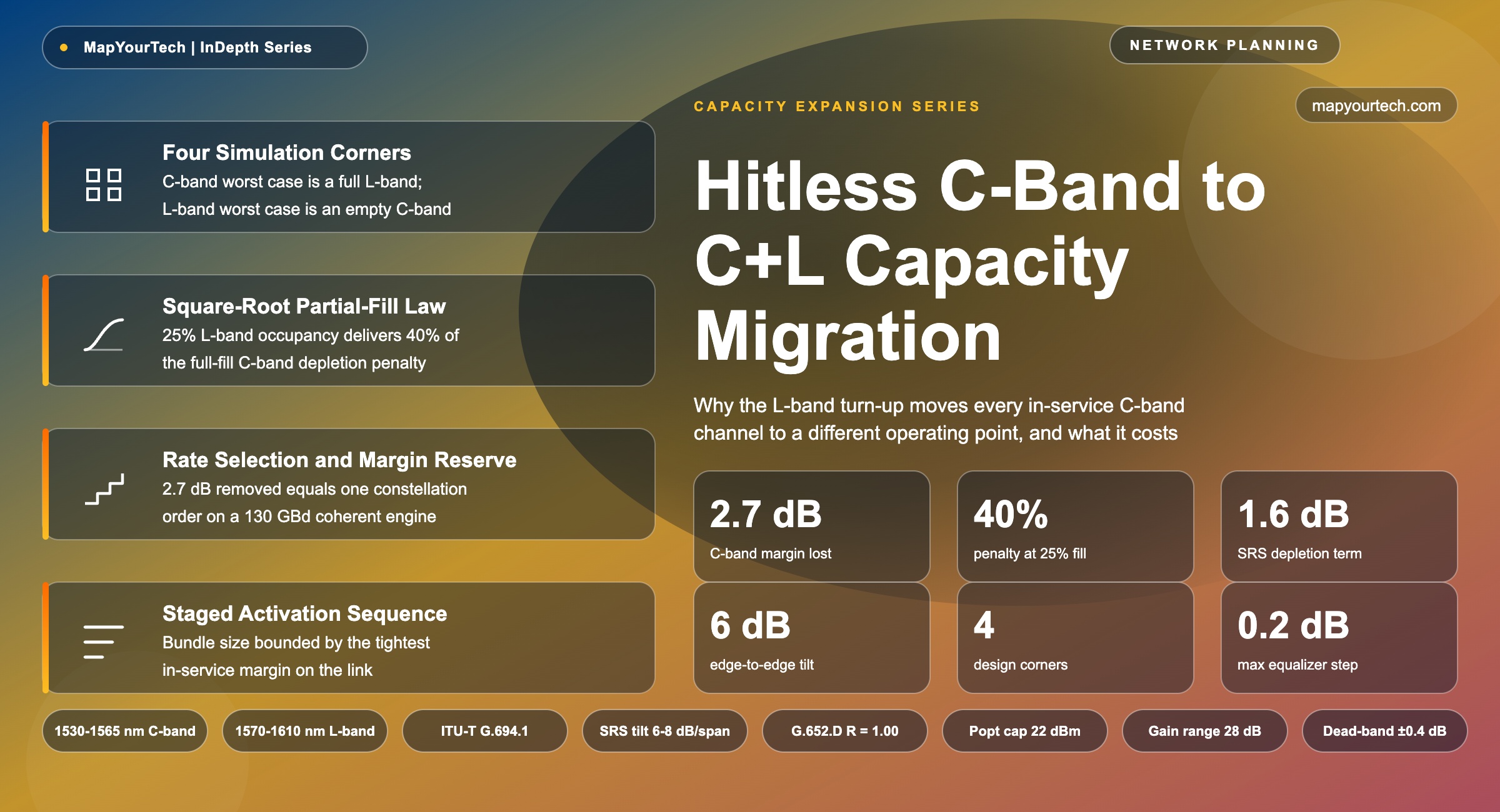
Hitless C-Band to C+L Capacity Migration
Activating the L-band on a fiber already carrying C-band traffic changes the operating point of every in-service channel. This article sets out the physical mechanism, the square-root law that governs how fast the penalty arrives with partial fill, the rate-selection decision that separates a hitless upgrade from a traffic-affecting one, and the equalization sequence that has to hold the line while the band fills.
1. Introduction
A fiber pair carrying 96 C-band channels at a total launch power near 22 dBm delivers a per-channel generalized signal-to-noise ratio (GSNR) that a planning tool computed against one specific spectral occupancy: C-band only, nothing above 1567 nm. The first L-band channel lit on that same fiber changes the operating point of all 96 in-service channels at once. Stimulated Raman scattering (SRS) begins moving power out of the C-band and into the L-band inside the transmission fiber itself, the band coupler that combines the two bands adds loss at both ends of every span, and each amplifier has to run at higher gain to restore what the fiber removed. On an 80 km G.652.D span at that launch power, the aggregate effect on the C-band is a loss of roughly 2.7 dB of delivered GSNR, with the shortest-wavelength channel losing more than 3 dB relative to the C-band-only condition [modeled from a production planning-tool formulation].
Two point seven decibels is not a rounding error. On a modern coherent engine it is the distance between two adjacent rungs of the line-rate ladder, sometimes two. A 600 Gb/s channel provisioned with 1.1 dB of margin against a C-band-only design case has negative margin the day the L-band fills. It does not degrade gracefully. Forward error correction holds until it does not, and then the channel drops. The upgrade that was sold internally as a capacity doubling becomes an outage on the traffic that was already paying for the fiber.
The mistake this article is written to prevent is not a mistake in the physics. It is a mistake about which design corner the in-service line rate was selected against. C+L planning has four corners, not two, and the corner that governs an in-service C-band channel after the upgrade is the one combining end-of-life fiber loss with a fully occupied L-band. Very few C-band-only turn-ups are validated against it, because at turn-up there is no L-band to model. The rate that looked comfortable at commissioning was measured against the most favorable corner of the design space, and the upgrade walks the system to the least favorable one.
1.1 Scope and Prerequisites
The treatment assumes working familiarity with coherent DWDM transmission and with GSNR as a quality-of-transmission metric. Readers who need a refresher on how amplified spontaneous emission accumulates along a chain of amplifiers should review OSNR fundamentals before the modelling sections. What follows covers, in order: how band-dedicated C+L line systems came to be built the way they are; the physical mechanism of inter-band power transfer and why its magnitude depends on total power rather than channel count; the architecture choices that decide whether an upgrade needs a fiber break; a closed-form treatment of partial fill that answers the question operators actually ask, which is how much penalty arrives with the first quarter of the L-band; the activation sequence and the control-loop behavior that constrains how fast the band can be filled; the GSNR budget and its relationship to the rate ladder; deployment scenarios; a comparison against the alternatives to a C+L upgrade; the failure modes that survive good planning; and where multiband work is heading.
1.2 The Central Claim
An L-band activation is hitless when the delivered C-band GSNR at the worst corner stays above the required GSNR of every in-service channel throughout the fill sequence. Every other element of the upgrade — the coupler, the amplifiers, the ASE loading, the equalization controller, the bundle sizing — exists to make that inequality hold or to spend the margin in increments small enough that no channel crosses its threshold on any single step. The inequality is set years earlier, at the moment someone chooses the line rate for the first C-band wavelength. That choice is the article's subject.
Select in-service C-band line rates against the end-of-life, full-L-band corner even when no L-band hardware is funded. The cost of holding one rung lower is a few percent of day-one capacity. The cost of not holding it is a forced regeneration or a rate downgrade on live traffic during the capacity expansion that was supposed to relieve congestion.
Takeaway: L-band activation removes roughly 2.7 dB of C-band GSNR on a typical 80 km G.652.D span — one to two rungs of the line-rate ladder. Whether that is absorbed silently or drops traffic depends entirely on which design corner the in-service rate was chosen against.
2. Development of Band-Dedicated C+L Line Systems
Erbium-doped fiber amplifiers (EDFAs) reach usable gain across roughly 1530 to 1565 nm with a standard aluminium-germanium-silicate host. Extending erbium emission to the 1570–1610 nm window requires a longer doped fiber operated at lower inversion, which produces a different gain shape and a noise figure typically 1 to 2 dB higher than the same design in the C-band [measured, device literature]. That single materials fact determined the architecture of every terrestrial C+L system built since: two separate amplifier chains, one per band, joined to a single transmission fiber through a wavelength-selective coupler. There is no practical single-stage amplifier covering both bands with acceptable flatness, so band-dedicated amplification is not a design preference but a consequence of the gain medium. The background on erbium gain shaping and noise-figure behavior is covered in the MapYourTech guide to EDFA technology.
2.1 From Capacity Doubling to Coupled Bands
L-band operation was proposed in the late 1990s as a way to double channel count on installed fiber. The economics were obvious then and remain obvious now: an additional 4.75 THz of usable spectrum on a fiber pair already trenched, spliced and permitted costs far less per bit than a new route. What was not obvious in the era of 10 Gb/s on-off keying was how strongly the two bands would interact once launch powers rose. At the aggregate powers used for 10 Gb/s direct-detection systems, inter-band Raman transfer over a single span was a fraction of a decibel and could be absorbed by static tilt settings. At the aggregate powers used by coherent systems filling 96 channels across the C-band, the same mechanism produces several decibels per span, and it changes whenever occupancy changes.
The industry response arrived in three waves. The first added L-band amplifiers and a coupler to existing C-band designs and accepted the resulting performance loss, which is why early C+L systems delivered noticeably less than twice the capacity of the C-band system they extended. The second wave added wide-range tilt compensation to both amplifier chains, so the slope introduced by the fiber could be pre-cancelled at each amplifier output rather than accumulated. The third wave, and the current state of practice, moved the problem earlier: occupy the whole spectrum with shaped amplified spontaneous emission from the day the line system is commissioned, so that the amplifier gain and tilt targets are established once, against a full-fill condition, and never have to move again as real traffic replaces the noise.
2.2 Calibration Timing as the Deciding Constraint
The third wave exists because of a constraint that is easy to miss on a product datasheet. Setting the gain and tilt targets of a C+L amplifier chain correctly requires driving the line to its final spectral loading and measuring what comes back. On a line already carrying revenue traffic, that procedure cannot be run: the calibration sweeps themselves move channel powers by more than in-service margin allows. One vendor states the constraint directly, noting that C+L amplifier calibration cannot be performed on networks with in-service C-band channels, which results in suboptimal system performance and reduced capacity [vendor claim]. The same source notes that a C+L coupler installed for a future upgrade requires additional day-one margin, which further reduces overall system capacity [vendor claim].
That is the whole argument for full-spectrum ASE loading compressed into two sentences. If the amplifiers are calibrated at full fill before any traffic exists, the upgrade later consists of swapping noise for signal at constant power, which the control loops absorb without leaving their stable state. If they are not, the upgrade requires a calibration that the traffic will not permit, and the operator is left choosing between a maintenance window and a permanently de-rated line. Related background on holding a line system at full occupancy through its service life is covered in the MapYourTech article on ASE channel loading.
| Generation | Amplification | Tilt handling | Upgrade behavior | Delivered capacity gain |
|---|---|---|---|---|
| First | C-band EDFA plus bolt-on L-band EDFA and coupler | Static tilt setting per span | Requires fiber break to insert coupler | Well below 2× |
| Second | Band-dedicated EDFAs with wide-range tilt control | Dynamic tilt tracking occupancy | Coupler pre-fitted; amplifier recalibration still needed | Approaching 2× on short links |
| Third (current) | Band-dedicated EDFAs, optional distributed Raman, integrated ASE loading | Tilt calibrated once at full fill | Swap noise for traffic in bundles; no recalibration | Close to 2× across the reach envelope |
Read the Full Analysis with Premium
The remaining 89% of this article — the design numbers, trade-offs and field guidance — is part of MapYourTech Premium, along with the full premium library, courses and professional tools.
You May Also Like

-
Free
-
September 4, 2026

-
Premium
-
September 4, 2026

-
Premium
-
September 4, 2026