
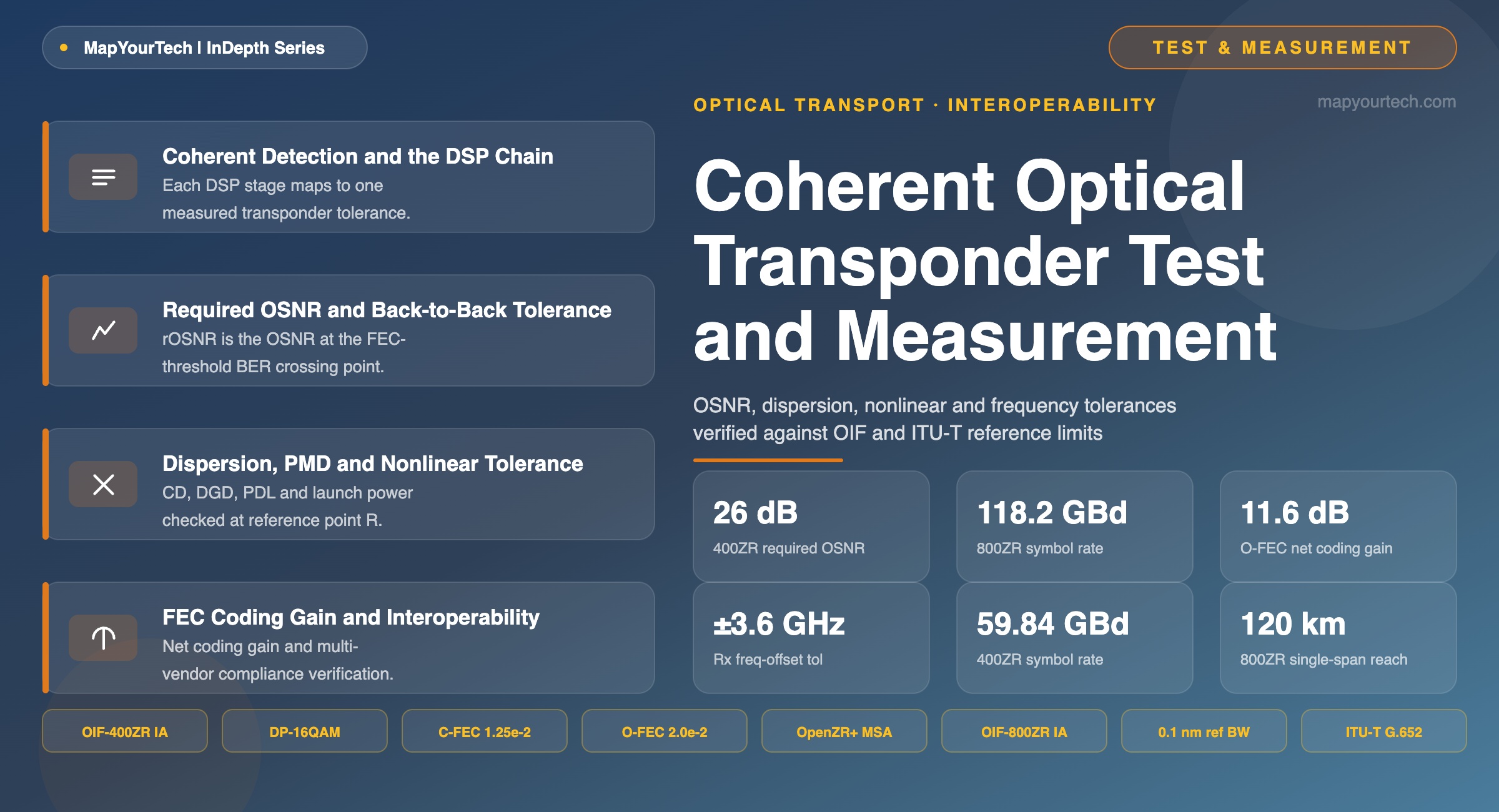
Coherent Optical Transponder Test and Measurement
A working reference on how coherent transponders and line systems are verified: required OSNR and back-to-back tolerance, chromatic dispersion and PMD tolerance, nonlinear tolerance, frequency accuracy, laser linewidth, and compliance testing against OIF and ITU-T interface specifications.
1. Introduction
A coherent transponder mixes the incoming optical field with a local-oscillator (LO) laser, recovers in-phase and quadrature components on two orthogonal polarizations, and hands four real-valued signal dimensions to a digital signal processor (DSP) that reconstructs the transmitted symbols. That receiver architecture changed what a transponder test measures. A direct-detection 10G receiver was characterized mostly by receiver sensitivity and dispersion penalty. A coherent 400G or 800G module is characterized by a set of tolerances — how much amplified spontaneous emission (ASE) noise it survives, how much accumulated dispersion and differential group delay its equalizer removes, how much carrier frequency offset and laser phase noise its carrier recovery tracks — because the DSP compensates the linear impairments that used to appear as penalties.
Each of those tolerances is a number a test engineer confirms against a specification. The Optical Internetworking Forum (OIF) 400ZR and 800ZR Implementation Agreements, the OpenZR+ Multi-Source Agreement (MSA), and the ITU-T G-series interface Recommendations define the required optical signal-to-noise ratio (OSNR) at a receiver reference point, the frequency-grid accuracy a transmitter holds, the dispersion and polarization-mode dispersion (PMD) an equalizer accommodates, and the forward-error-correction (FEC) coding gain a link relies on. A transponder that reports zero post-FEC errors on a clean bench can still fail a network if its required OSNR sits above the delivered OSNR after real spans, or if its transmitter frequency drifts outside the grid a reconfigurable optical add-drop multiplexer (ROADM) filter expects.
This article treats coherent transponder test and measurement as an engineering discipline rather than a checklist. It states each tolerance, the physical mechanism it protects against, the measurement method that produces the number, and the standard clause the number is checked against. The audience is mixed: an engineer meeting coherent test for the first time will find the mechanism explained; an engineer running an interoperability lab will find the OIF and OpenZR+ test conditions stated with their evidence class. Where a value comes from a published Implementation Agreement it is labeled standard-specified; where it comes from a vendor datasheet it is labeled a vendor claim; where it is a physical bound it is labeled a theoretical limit. The scope is terrestrial pluggable and embedded coherent interfaces from 400G to the 1600G generation now in development; it does not cover submarine line-terminal test, which uses different power budgets and repeater conditions.
2. Coherent Detection Fundamentals
The reason coherent test differs from direct-detection test is that coherent detection preserves the optical field, not just its intensity. A 90-degree optical hybrid beats the received signal against the LO and produces four photocurrents that carry the in-phase and quadrature components on the X and Y polarizations. Balanced photodiodes and analog-to-digital converters (ADCs) sample those four tributaries, and from that point every impairment is a mathematical operation the DSP inverts. A single wavelength carries four bits per symbol on dual-polarization 16-state quadrature amplitude modulation (DP-16QAM), because each polarization carries a 16QAM constellation of four bits. That four-dimensional encoding is what lets a 75–150 GHz channel carry 400–800 Gb/s.
The DSP chain matters to the test engineer because each block maps onto a measured tolerance. Chromatic dispersion (CD) is removed by a fixed frequency-domain equalizer; the CD tolerance test confirms how much accumulated dispersion that stage inverts. A multiple-input multiple-output (MIMO) adaptive equalizer, typically driven by the constant-modulus algorithm (CMA), tracks polarization rotation, PMD, and polarization-dependent loss (PDL); the PMD and state-of-polarization (SOP) tolerance tests exercise that stage. Frequency-offset estimation removes the beat between the transmitter laser and the LO; the frequency-offset tolerance test sets how far apart the two lasers can sit. Carrier-phase recovery removes laser phase noise; the linewidth tolerance test bounds the combined transmitter-plus-LO linewidth the recovery loop survives. The relationship between these DSP stages and the tests that exercise them is shown in Figure 1.
Read the Full Analysis with Premium
The remaining 89% of this article — the design numbers, trade-offs and field guidance — is part of MapYourTech Premium, along with the full premium library, courses and professional tools.
You May Also Like

-
Free
-
September 4, 2026

-
Premium
-
September 4, 2026

-
Premium
-
September 4, 2026