
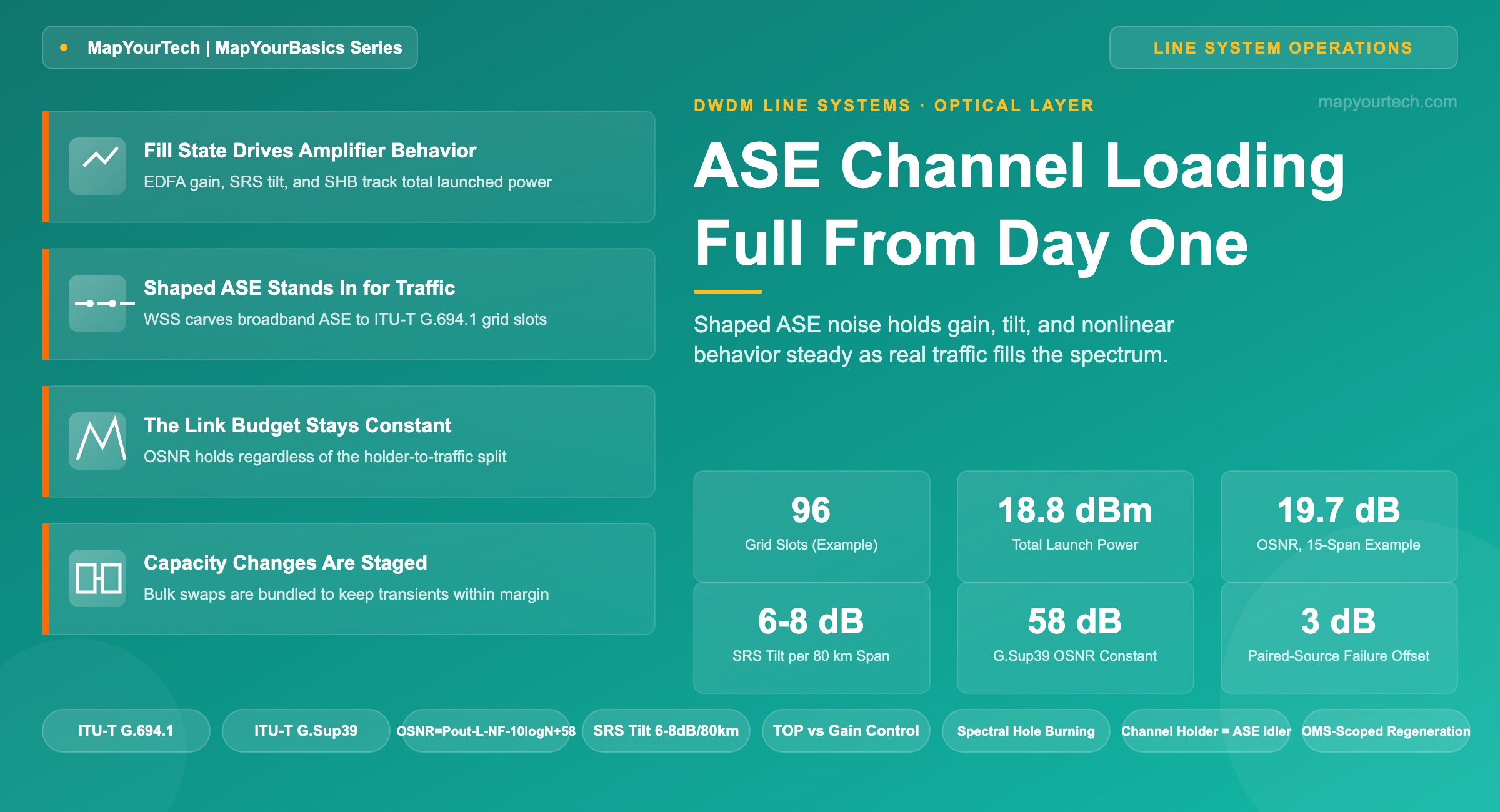
ASE Channel Loading: Running a Line System Full From Day One
How shaped ASE noise holds amplifier gain, Raman tilt, and nonlinear operating points steady while a DWDM line system fills with real traffic over its service life.
1. Introduction
A newly commissioned C-band line system carrying four live wavelengths behaves, from an amplifier's point of view, nothing like the same system carrying eighty. An erbium-doped fiber amplifier (EDFA) responds to the total optical power arriving at its input, not to how many of the wavelengths inside that power happen to be carrying data. Set the gain and tilt targets for four channels, then add seventy-six real ones over the following two years, and every downstream amplifier moves further into saturation, gain ripple redistributes across the band, and the Raman-driven tilt between the short and long wavelength edges shifts with each large capacity change. ASE channel loading — filling the unused spectrum with amplified spontaneous emission (ASE) shaped to match a live channel's power and bandwidth — is the industry answer to that problem: launch the system at full spectral occupancy on day one using shaped noise in place of traffic, then swap real channels in as they are provisioned, one grid slot at a time.
This article covers what a channel holder is and how it differs from ordinary ASE, why amplifier gain, Raman tilt, and the nonlinear operating point depend on total launched power rather than on channel count, the link-budget arithmetic that explains why a full spectrum keeps OSNR predictable at any fill state, and what changes operationally — slot switching, staged capacity changes, and failure handling — when live traffic takes over spectrum that shaped noise used to occupy.
2. What Channel Loading Means
A channel holder is optical power without traffic. It is amplified spontaneous emission, sliced at a Wavelength Selective Switch (WSS) into blocks that match a live channel's center frequency, occupied bandwidth, and target launch power on the ITU-T G.694.1 frequency grid. Vendor documentation uses "channel holder," "ASE idler," and "loading channel" interchangeably — they describe the same construct: a spectral slot filled with shaped noise so that, from the amplifier's perspective, the slot looks occupied whether or not a transponder is actually driving it.
The practice did not start with terrestrial ROADM networks. Submarine cable systems have long pre-loaded a full band of ASE across the Submarine Line Terminal Equipment (SLTE) before any traffic channel is turned up, because a submarine repeater chain has no local access for re-tuning once deployed — its gain and tilt targets have to be right on the first attempt and stay right for the life of the cable. Terrestrial open line systems adopted the same idea for a more mundane reason: a line system sold with headroom for ninety-six channels is commercially provisioned for four, and the amplifiers still need to behave predictably as the other ninety-two are added over years of capacity growth.
Practical Example — Turn-Up With Partial Traffic
A newly turned-up 12-span, 960 km terrestrial C-band system is commissioned with 96 grid slots at 100 GHz spacing. On day one, four slots carry live 400G coherent wavelengths and the remaining 92 slots are filled with shaped ASE channel holders launched at the same target per-channel power as the traffic. The booster amplifier at the first node sees a full 96-channel load from the first day of service, even though 92 of those channels carry no bits, and its gain and tilt setpoints never have to be revisited as the other 92 channels are provisioned over the following months.
3. Why Amplifier Behavior Depends on Fill State
An EDFA converts pump power into signal gain, and that conversion compresses as total input power rises — the gain delivered to any one channel is a function of the aggregate power across the whole amplified band, not of that channel in isolation. Line amplifiers typically run under one of two control loops: constant-gain control, which holds a fixed gain regardless of input power, or total-output-power (TOP) control, which holds a fixed total output power regardless of how that power is distributed among channels. Under TOP control specifically, a sparsely filled system pushes more power into each active channel to reach the output setpoint, moving every live channel to a different point on its nonlinear-penalty curve than the point the system was engineered for. A channel holder removes that variability by keeping the total input power the amplifier sees constant across its life, regardless of how many of the occupied slots are carrying real traffic.
Stimulated Raman Scattering (SRS) compounds the problem. SRS transfers energy from shorter-wavelength channels to longer-wavelength channels as they co-propagate through the fiber, producing a spectral tilt that depends on total launched power and occupied bandwidth, not on how many of the occupied slots are modulated with data. In a fully loaded C+L band system, published field and vendor data place this tilt in the range of 6 to 8 dB per 80 km span at typical C+L launch powers — see the MapYourTech guide on C+L band DWDM system design for the full derivation. Because the tilt is driven by aggregate power and bandwidth, a system whose spectral occupancy changes every time a channel is added or dropped experiences a moving tilt target, which is exactly what Raman amplifier tilt-correction stages are built to chase. Full-fill loading removes the motion: the tilt is set once, against the full-band condition, and stays there.
A related effect, Spectral Hole Burning (SHB), changes the local gain an EDFA offers around whichever wavelengths are carrying the most power at any instant — see the dedicated article on spectral hole burning for the mechanism. SHB is also a function of the instantaneous power distribution across the band, so a spectrum that keeps that distribution constant — full at commissioning, full for the life of the system — keeps SHB's effect constant as well.
Here is the boundary: shaped ASE reproduces the aggregate power profile a live channel would present, but its spectral content is broadband noise rather than a modulated signal. An optical channel monitor (OCM) that inspects only total power per slot cannot tell the difference, which is the entire point — but a monitor that checks trace shape against the narrower spectral mask a modulated signal occupies can distinguish a holder from traffic without any signaling between nodes. That distinction is what lets a node auto-squelch a failed traffic channel by replacing it with a holder without waiting for an end-to-end control-plane message.
4. Generating and Managing Shaped ASE Loading
A broadband ASE source — typically an EDFA or a dedicated multi-line amplifier run open-loop — feeds a WSS. The WSS attenuates and shapes that broadband noise into per-slot blocks matching the ITU-T grid spacing and the target launch power for that slot, then those blocks are combined with any live traffic at the multiplexer stage before the booster amplifier. At every downstream ROADM add/drop point, holders inherited from the upstream section are dropped or blocked, and new holders are regenerated locally so that each Optical Multiplex Section (OMS) is independently full-filled. A channel holder is never expected to survive an entire end-to-end path — it is manufactured and consumed section by section, which keeps the loading logic local to each node rather than dependent on a network-wide view.
5. The Link Budget With and Without Loading
The reason loading keeps the amplifier chain predictable comes down to a short piece of arithmetic. Total launched power depends on the number of occupied grid slots and the per-channel power target — not on which of those slots carry data.
Total Launched Power — Full-Fill Condition
Ptotal = 10 · log10 ( Ntotal · 10^(Pch / 10) )
Where: Ptotal is the aggregate launched power in dBm; Ntotal is the number of occupied grid slots (traffic plus holders); Pch is the target per-channel power in dBm, held equal for holders and traffic. Because Ntotal is fixed by the full-fill condition rather than by the traffic count, Ptotal does not change as traffic replaces holders — this is a theoretical-limit expression, not a measured value.
Practical Example — Power Is Independent of the Traffic/Holder Split
A 96-slot C-band system targets −1 dBm per channel. With 4 real traffic channels and 92 ASE holders, total launched power is 10·log10(96 · 10−0.1) ≈ 18.8 dBm. After two years, when 60 of the 96 slots carry real traffic and 36 remain holders, the same calculation — 10·log10(96 · 10−0.1) — still returns 18.8 dBm, because the slot count and per-channel target have not changed. The booster amplifier's operating point never moves.
The same full-fill assumption carries through to OSNR. ITU-T G.Sup39 gives the standard-specified worst-case OSNR estimate for a multi-span chain with equal span losses and equal per-channel output power at each amplifier:
OSNR — ITU-T G.Sup39 Simplified Form (0.1 nm Reference Bandwidth)
OSNR = Pout − L − NF − 10 · log10(N) + 58
Where: Pout is the per-channel output power of the booster and line amplifiers (dBm); L is the span loss in dB (assumed equal to line-amplifier gain); NF is the amplifier noise figure (dB); N is the number of line amplifiers; the constant 58 dB comes from 10·log10(h·ν·νr) evaluated at 1550 nm with a 0.1 nm reference bandwidth. This is a standard-specified formula, drawn from ITU-T G.Sup39, Equation 9-19.
Because loading holds Pout constant per channel regardless of fill state, an OSNR figure calculated once at commissioning — for a channel-holder slot or a live channel, the formula does not distinguish them — stays valid as traffic replaces holders. For a 15-span link at Pout = +1 dBm, L = 22 dB, NF = 5.5 dB: OSNR ≈ 1 − 22 − 5.5 − 10·log10(15) + 58 ≈ 19.7 dB, an illustrative calculation using the standard formula above. That number is the same whether the operator runs it against a holder slot during commissioning or against the live channel that later occupies it — which is what lets a commissioning-time OSNR margin calculation stand without being re-run at every capacity change, and what an optical channel monitor confirms in the field.
| Metric | Sparse / Under-Filled | ASE-Loaded (Day-1 Full-Fill) | Live Traffic (Post-Swap) |
|---|---|---|---|
| Total launched power | Varies with real channel count; rises as traffic is added | Fixed at the day-1 target across the full grid | Unchanged — traffic replaces holders one for one |
| EDFA operating point | Shifts toward less saturation as occupied slots change | Set once at commissioning; held for system life | No re-tuning required for like-for-like swaps |
| SRS-driven spectral tilt | Changes with every large add or drop event | Stable — full-band Raman interaction from day one | Stable, provided swaps are staged (see Section 6) |
| OSNR margin at commissioning | Calculated for a future fill state that does not yet exist | Calculated once, against the true operating condition | Matches the commissioning-time calculation |
| Capacity-change operational load | Amplifier re-optimization cycle on every major add or drop | Not applicable — system already at target fill | WSS slot switch only; no amplifier re-tuning |
6. What Changes When Traffic Displaces Loading
When a channel is provisioned, the local WSS switches that one slot from shaped ASE to the traffic add port. Because the swap is like-for-like in power and spectral shape, the amplifier's control loop — gain-clamped or TOP-controlled — sees no net change in aggregate input power, so the channels already in service do not experience a transient from that single swap. The exposure shows up at scale: swapping a large block of holders for traffic in a single action moves a meaningful fraction of the band's spectral shape at once, and the surviving channels can see a measurable power offset from the combined effect of SRS tilt redistribution, amplifier gain ripple, and spectral hole burning settling to a new steady state. That is why bulk capacity changes on a loaded line system are staged in smaller bundles rather than executed as one shot — each bundle stays inside the margin the surviving channels can absorb, at the cost of a longer overall turn-up sequence. The same staging discipline applies to mixed channel-rate line systems, where the surviving channels' OSNR margin already varies by modulation format before any transient is added.
Channel holder sources themselves can fail. Because a holder failure removes real optical power from the spectrum in exactly the way a fiber cut or a transponder failure would, operators typically pair holder sources — combining optical power from two sources so that a single failure drops total power by roughly 3 dB rather than opening an unbounded gap — or draw replacement power locally from an adjacent, optically interconnected degree at the same node. The same local, section-scoped logic that generates holders in the first place is what lets a node auto-squelch an unexpected traffic drop: when a live channel disappears because of an upstream fault, the first downstream section-multiplexer replaces that slot with a matching ASE holder immediately, without waiting for any end-to-end signaling, which keeps the total launched power at that point constant and limits how far the SRS-driven power imbalance propagates before the fault is cleared.
Takeaway: The amplifier chain cannot tell a well-shaped holder from a live channel by power alone, which is exactly the property that makes channel loading work — but that same property means every operational safeguard has to come from staging swaps in bounded steps, pairing holder sources for redundancy, and letting the local node auto-squelch faults, rather than from any change in amplifier setpoints.
7. Practical Guidelines for Operators
- Provision channel holders to the same per-channel power target used for planned traffic, not an averaged or rounded value — a mismatched holder power is what creates the transient the technique exists to avoid.
- Match each holder's spectral shape — bandwidth and edge roll-off — to the grid slot it occupies, and confirm it against an OCM trace rather than a simulation alone.
- Stage large capacity changes as a sequence of smaller holder-to-traffic swaps instead of a single bulk action, keeping each step's transient inside the surviving channels' OSNR margin.
- On TOP-controlled amplifier chains, plan loading per Optical Multiplex Section independently — holders regenerate at every ROADM and are not expected to survive end-to-end.
- Where the redundancy budget allows, pair channel holder sources so a single hardware failure produces a bounded, known power offset instead of an open spectral gap.
8. Conclusion
Channel loading is a quiet piece of the optical layer. It carries no bits, appears on no service order, and its only visible signature is that the amplifier chain behaves the same on commissioning day as it will years later at full capacity. As line systems widen into C+L band and beyond, and as the cost of leaving planned spectrum idle grows harder to justify against the cost of keeping it shaped and stable, shaped ASE will keep doing the job it has done since the earliest submarine deployments: holding the physical layer's operating point still while the traffic layer above it changes shape. The measure of a well-run line system is that nobody notices the moment a wavelength moves from noise to data.
References
- ITU-T G.694.1 — Spectral grids for WDM applications: DWDM frequency grid, ITU-T Study Group 15.
- ITU-T G.Sup39 — Optical system design and engineering considerations, ITU-T Study Group 15.
- Sanjay Yadav, "Optical Network Communications: An Engineer's Perspective" – Bridge the Gap Between Theory and Practice in Optical Networking.
Related Articles on MapYourTech






