
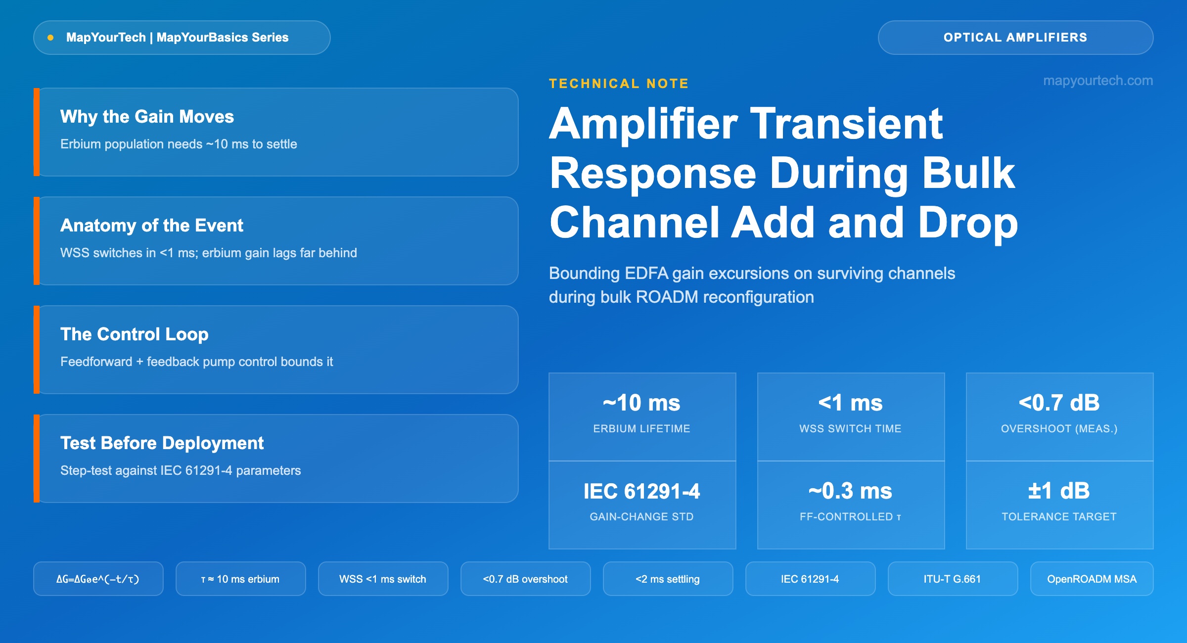
Amplifier Transient Response During Bulk Channel Add and Drop
What happens to surviving channels in the milliseconds after a large add or drop event, the control-loop settings that bound the excursion, and how to test the behavior before it tests you.
1. Introduction
A wavelength-selective-switch (WSS) reconfiguration that drops sixty of eighty channels at a ROADM degree changes the total input power to the downstream booster erbium-doped fiber amplifier (EDFA) by roughly 5 dB, and the switch itself completes the change in under a millisecond (reported, industry trade-press figure). The erbium ions supplying gain to the twenty surviving channels do not know sixty channels just left. They keep converting pump photons into signal photons at the rate their population inversion allows, and that population takes on the order of 10 milliseconds (measured, standard erbium-fiber physics value) to settle into a new equilibrium. In the gap between a fast optical switch and a comparatively slow gain medium, the surviving channels ride a power excursion that can approach the size of the power step itself.
This article works through where that excursion comes from physically, the feedforward-plus-feedback control-loop architecture used to bound it, a first-order model for estimating its size and duration, the provisioning and design guardrails operators use to keep it out of trouble, and a test method for characterizing an amplifier's transient response before a live reconfiguration event does the testing for you. The scope is EDFA-based line and ROADM-adjacent amplifiers; distributed Raman amplification is referenced only for contrast, since its transient mechanism and timescale are different by more than two orders of magnitude.
2. Why the Gain Moves: EDFA Dynamics on the Millisecond Scale
An EDFA amplifies through stimulated emission from erbium ions sitting in a metastable excited state, pumped there by a 980 nm or 1480 nm laser. The photon lifetime from that metastable state back to the ground state runs roughly 10 to 10.5 milliseconds (measured, standard erbium-fiber physics value), while the lifetime from the higher pump-excited state down into the metastable state is on the order of 1 microsecond. Because the second transition is thousands of times faster than the first, erbium ions accumulate in the metastable state and the population there, denoted N2, becomes the quantity that sets the amplifier's gain at any instant. Steady-state gain follows G = exp(σe·N2·L), where σe is the emission cross-section and L is the doped-fiber length — so any external event that forces N2 to a new value shows up externally as a gain change, and the ~10 ms metastable lifetime is what paces how fast N2 can get there.
In a WDM system operating in gain saturation — which most in-line and booster EDFAs do by design, for efficiency — all channels sharing the fiber compete for the same finite population inversion. Remove a large fraction of the channels and the ions that were serving them are suddenly available to the survivors, so surviving-channel gain rises: an overshoot. Add channels back and the reverse happens — the newcomers pull inversion away from the already-established channels, whose gain sags: an undershoot. This bidirectional cross-saturation is the mechanism, and its magnitude scales with how deeply the amplifier was saturated before the event, not with the absolute channel count.
For contrast, distributed Raman amplification responds through stimulated scattering that is close to instantaneous at the photon-interaction level, but the system response is set instead by the propagation delay of pump and signal walking past each other along kilometers of fiber. A measured transient on a counter-pumped discrete Raman amplifier built from 13.9 km of dispersion-compensating fiber settled in about 50 microseconds following a 50% step in input signal power (measured, published research). EDFA transients are reported to run substantially larger in both magnitude and duration than Raman transients under comparable conditions — a direct consequence of the 10 ms erbium lifetime versus the microsecond-scale walk-off delay that governs Raman dynamics. For background on how distributed gain interacts with span budgets more broadly, see MapYourTech's note on distributed Raman amplification.
3. Anatomy of a Bulk Add/Drop Event
Bulk add/drop events come from a handful of recurring triggers: a mesh reroute after a fiber cut moves dozens of wavelengths onto a protection path in one WSS switching operation, a maintenance window bulk-migrates traffic off a degree before work begins, or a ROADM degree failure drops every channel on one direction simultaneously. In each case the optical switching itself is fast — WSS-based ROADM add/drop typically completes in under 1 millisecond (reported, industry trade-press figure) — so from the amplifier's perspective the total input power looks close to a step function rather than a ramp.
The amplifier's own input photodiode tap sees that step almost immediately; the pump-power adjustment and the underlying population-inversion relaxation do not. The result plays out on the surviving channels exactly as the cross-saturation mechanism predicts: an overshoot immediately after a channel drop, an undershoot immediately after a channel add, each decaying back toward the new steady-state gain over a timescale set by the amplifier's effective relaxation time. Left uncorrected, the overshoot case pushes surviving-channel power into a regime with a higher risk of fiber nonlinearity and, in extreme cases, receiver overload or optical-component stress; the undershoot case degrades OSNR on the surviving channels and can trigger error bursts if the margin was already tight.
A second effect compounds the first: the excursion does not stay local to one amplifier. Each amplifier's imperfectly corrected transient becomes the input step for the next amplifier in the chain, so the magnitude and settling time of the disturbance tend to grow as it propagates through a cascade of concatenated EDFAs rather than staying fixed. This is the reason transient-response specifications matter more on long multi-span links than on a single-hop metro connection, and why a control loop tuned and verified on one amplifier in isolation is not automatically adequate once it sits in a ten-span chain.
Practical Example — Bulk drop under measurement
A published characterization of a feedforward-and-feedback-controlled EDFA dropped 79 of 80 WDM channels in one step — a 19 dB input-power reduction — and held the surviving channel's gain deviation below 2 dB throughout the event (measured, published research demonstration). A separate characterization on the same amplifier class, stepping through drops of 1, 3, 7, 15, and 31 of 32 channels, measured a maximum 0.6 dB deviation from the set gain point, and reported that combining the optical and electronic control paths cut the overall transient impact to under 2 milliseconds with peak overshoot/undershoot below 0.7 dB (measured, published research demonstration). Neither figure is a universal spec — both depend on the specific amplifier's saturation depth and loop tuning — but they establish the order of magnitude a well-controlled EDFA can reach versus the multi-decibel, multi-millisecond excursion an uncontrolled amplifier produces under the same step.
4. The Control Loop That Bounds the Excursion
Production EDFAs bound the transient with a combined feedforward and feedback architecture rather than either technique alone. A fast photodiode taps the input signal ahead of the erbium-doped fiber; a feedforward controller reads that tap, computes the pump-current adjustment the step calls for, and applies it to the pump driver before the population inversion has had time to drift on its own. A second photodiode taps the output, and a feedback controller — commonly a proportional-integral-derivative (PID) design — trims the residual error against the amplifier's power or gain setpoint.
The two loops trade off different failure modes. Feedforward is fast: its loop delay is set by photodiode bandwidth and driver electronics, typically microseconds, because it reacts to the measured input change rather than waiting for the gain medium to show a symptom. But feedforward is open-loop with respect to the actual output — it is only as accurate as its calibration against amplifier saturation characteristics that drift with temperature and aging. Feedback is accurate, because it converges on the true measured setpoint, but its usable bandwidth is capped by loop-stability margins, so acting alone it would still let the roughly 10 ms erbium relaxation time dominate the visible transient. Combining both narrows the peak excursion to a fraction of the input step and cuts settling time by more than an order of magnitude compared with either loop running by itself.
A First-Order Model for the Excursion
The gain deviation following a step change can be approximated with a single-pole relaxation model — a reasonable first-order fit for a single amplifier operating away from deep saturation extremes, and the same functional form used in the control-theory literature to describe both uncontrolled and gain-controlled EDFA recovery.
- ΔG(t) — gain deviation from the new steady state at time t after the step (dB)
- ΔG0 — initial gain deviation immediately following the step (dB); bounded in magnitude by the input-power step itself when the amplifier is deeply saturated
- τ — effective gain relaxation time constant (s); set by the erbium upper-state lifetime (≈10 ms) in an uncontrolled amplifier, or by the combined feedforward/feedback loop bandwidth in a gain-controlled amplifier
- t — elapsed time since the step event (s)
This is a simplified single-pole approximation, not a full coupled-rate-equation solution — it is adequate for sizing settling time and worst-case excursion, not for predicting spectral gain tilt during the transient, which requires the full wavelength-resolved model.
Practical Example — Settling Time, Controlled vs. Uncontrolled
Take ΔG0 = 4 dB, representative of a deeply saturated booster losing roughly 60% of its input channels in one step. An uncontrolled amplifier relaxing at the bare erbium time constant, τ = 10 ms, reaches ΔG(τ) = 4 × e−1 ≈ 1.47 dB after 10 ms and does not fall under 0.2 dB until roughly t = 3τ ≈ 30 ms. A feedforward-assisted loop that pulls the effective time constant down to τ = 0.3 ms reaches the same 0.2 dB threshold at t = 3τ ≈ 0.9 ms — over 30 times faster, for the identical size of input step. This is an illustrative calculation from the stated model, not a measured vendor figure; treat it as a way to reason about order-of-magnitude improvement, and validate actual settling time against the amplifier's own datasheet and the step-response test described in Section 6.
| Parameter | Typical Value / Range | Evidence Class | Source Context |
|---|---|---|---|
| Erbium upper-state (metastable) lifetime | ≈ 10–10.5 ms | Measured | Standard erbium-doped fiber physics |
| Discrete Raman amplifier transient (50% step, 13.9 km DCF, counter-pumped) | ≈ 50 µs | Measured | Published Raman-amplifier research |
| Mid-stage EDFA settling time, fast-controlled | < 200 µs (typical) | Reported | Industry trade-press / operator design target |
| WSS-based ROADM add/drop switching time | < 1 ms (typical) | Reported | Industry trade-press / operator design target |
| Surviving-channel peak-to-peak transient tolerance | ± 1 dB (commonly cited target) | Reported | Network-operator design target, trade press |
| Gain tilt tolerance for a 15 dB (32-channel) step | ± 0.5 dB (commonly cited target) | Reported | Network-operator design target, trade press |
| Multichannel gain-change difference | Defined parameter template, no universal numeric limit | Standard | IEC 61291-4 |
| Combined FF+FB transient impact (79/80 ch. drop, 19 dB step) | < 2 ms settling, < 0.7 dB overshoot/undershoot | Measured | Published AGC-EDFA research demonstration |
| Two-stage EDFA with fast link control channel (7/8 ch. drop) | 1.6 µs controller response time | Measured | Published gain-flattened EDFA research |
5. Guardrails: Design and Provisioning Practices
Electronic feedforward-plus-feedback control is the default, but it is not the only lever available, and a well-engineered node combines several of the following rather than relying on one.
All-optical gain clamping. An auxiliary lasing wavelength or lasing cavity built into the EDFA holds the population inversion essentially fixed regardless of how many signal channels are loaded, because the clamping laser itself consumes whatever gain the signal channels are not using. The trade-off is a reduction in usable output-power budget — power that would otherwise go to signal channels is instead spent maintaining the clamp — and added design complexity, but the transient response becomes largely decoupled from channel count rather than dependent on electronic loop tuning. For background on how gain is shaped and equalized across the C-band more broadly, see MapYourTech's explainer on EDFA gain flattening and equalization.
Spectral fill on channel drop. Rather than letting total input power fall when a channel is dropped, some ROADM and amplifier control schemes insert filtered amplified-spontaneous-emission (ASE) power into the vacated wavelength slot to hold total input power roughly constant, withdrawing the fill gradually once the real reconfiguration is complete. One disclosed implementation reports completing this substitution in under 50 milliseconds (vendor claim, patent disclosure) — fast enough to prevent the spectral-hole-burning and gain-tilt effects that an unfilled gap would otherwise cause on adjacent channels, at the cost of the added optical hardware and control complexity needed to synthesize and track a clean ASE-derived fill signal.
Staged reconfiguration in provisioning software. Where the traffic-engineering rules allow it, spreading a large bulk add/drop across several smaller steps, each timed apart by more than the amplifier's dominant time constant, keeps every individual step's excursion within the linear regime where feedforward calibration holds. A single 5 dB step and five sequential 1 dB steps do not produce the same peak excursion, because the smaller steps let the control loop fully settle between events rather than stacking disturbances.
Local control-loop placement. The OpenROADM Multi-Source Agreement defines transient control as one of a small number of control loops that stay local to the device rather than being abstracted into the centralized SDN controller (standard-specified, OpenROADM MSA) — every other optical control function in the architecture routes through the central controller. That exception exists because a round trip to a network-wide controller cannot meet a millisecond-class reaction requirement; the loop has to close inside the amplifier itself. Readers building or auditing a multi-vendor line system should see MapYourTech's overview of OpenROADM architecture and the related discussion of multi-vendor optical line system integration for how this local/central split fits the broader control-plane picture.
A control loop calibrated and verified at one operating point does not automatically hold across the amplifier's full dynamic gain range. Transient magnitude and settling time both scale with how deeply the amplifier is saturated before the event, so a loop that looks well-behaved at 50% loading can still produce a larger-than-expected excursion at 90% loading. Re-verify transient response whenever the node's typical channel count or launch-power plan changes materially.
6. Testing the Behavior Before It Tests You
Step-response testing is the direct way to characterize transient behavior rather than trusting a datasheet's nominal condition. The method: use a fast optical switch or WSS to add or drop a defined, worst-case fraction of channels abruptly at the amplifier's input, and capture the surviving channels' power over time on a fast photodiode and oscilloscope, or on a high-speed optical channel monitor (OCM) tap if oscilloscope access is not available. For a walkthrough of how OCM data feeds equalization and monitoring control loops more generally, see MapYourTech's guide to DWDM channel monitoring with OCM and OSA.
Three numbers come out of the capture and matter for sign-off: peak overshoot/undershoot in dB, settling time to a defined tolerance band (commonly ±0.5 dB or ±1 dB, matched to the link's actual OSNR and nonlinear margin), and gain tilt during the transient — the spectral asymmetry across the band, which is exactly the multichannel gain-change-difference parameter defined in the IEC 61291-4 (standard-specified) performance-specification template that amplifier datasheets report against.
Two conditions widen the test beyond a single nominal-point measurement. First, repeat the step across multiple operating points spanning the amplifier's dynamic gain range, not only the nominal design point, since both excursion size and settling time scale with saturation depth. Second, run the test through a representative cascade — a chain of concatenated amplifiers matching the network's longest engineered span count — because the excursion compounds through the chain rather than staying fixed at a single-amplifier value. A node's actual worst case is usually not the vendor's default test condition; it is the specific reconfiguration the provisioning rules permit, such as a full ROADM degree failure dropping every channel on one direction at once, and that scenario is the one worth reproducing on the bench before it happens live. Commissioning teams validating a new amplifier chain end-to-end can pair this transient test with the broader turn-up sequence in MapYourTech's DWDM system commissioning checklist, and link-budget context from the DWDM link design parameters reference helps translate a measured excursion into an actual margin impact. On disaggregated line systems, the amplifier's transient behavior also needs to be visible to whatever controller owns the open line system, a topic covered in MapYourTech's IP-over-DWDM architecture walkthrough, and the switching side of the same event is set by the WSS technology detailed in MapYourTech's wavelength-selective-switch technology reference.
7. Summary
The gap between a millisecond-class optical switch and a roughly 10-millisecond gain medium is not a defect to be engineered around once; it is a permanent physical mismatch that every bulk-reconfiguration event re-exposes, on every amplifier, for as long as EDFAs and WSS-based ROADMs share a network. Feedforward-plus-feedback control, all-optical clamping, spectral fill, and staged provisioning each narrow that gap through a different mechanism, and the right combination depends on the node's actual worst-case reconfiguration rather than a vendor's nominal test condition. Verifying the number on the bench, at the operating points and cascade depth the network will actually see, is what turns a datasheet claim into a network guarantee.
Takeaway: Surviving-channel power excursions during bulk add/drop come from the mismatch between millisecond-class WSS switching and the roughly 10 ms erbium gain-relaxation time; feedforward-plus-feedback control loops, all-optical gain clamping, and staged provisioning each narrow that gap by a different mechanism, and the only way to know which combination a given node needs is to step-test it at the worst-case reconfiguration and cascade depth the network will actually present.
References
- ITU-T G.661 — Definitions and test methods for the relevant generic parameters of optical amplifier devices and subsystems, ITU-T Study Group 15.
- IEC 61291-4 — Optical amplifiers – Part 4: Multichannel applications – Performance specification template, International Electrotechnical Commission.
- Open ROADM MSA — Device White Paper, Open ROADM Multi-Source Agreement.
Sanjay Yadav, "Optical Network Communications: An Engineer's Perspective" – Bridge the Gap Between Theory and Practice in Optical Networking.
Related Articles on MapYourTech






