Interconnection Engineering: Meet-Me Rooms, Cross-Connects, and Optical Handoffs
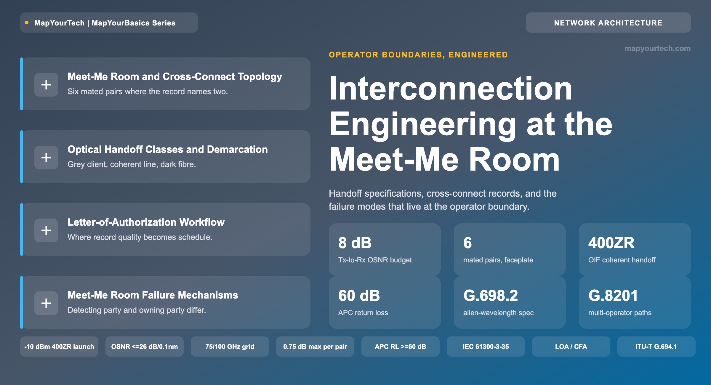
The engineering of operator boundaries: handoff specifications at the demarcation point, cross-connect management at scale, letter-of-authorization workflow, and the failure modes that live in the meet-me room.
1. Introduction
A cross-connect is a single fibre jumper between two ports on two patch panels in one room, and it is the point where two commercial and two engineering domains meet. Everything on one side of that jumper belongs to one operator's design, monitoring, and maintenance authority. Everything on the other side belongs to another. The jumper itself belongs to the facility operator, who installed it under a paper instruction from both parties and who will not touch it again unless one of them files a ticket.
That asymmetry is what makes interconnection an engineering discipline rather than a cabling task. Inside one operator's network, a wavelength's launch power, its receiver optical signal-to-noise ratio (OSNR), its chromatic dispersion accumulation, and its forward error correction (FEC) margin are all visible to one management system and controlled by one planning tool. At the meet-me room boundary, that visibility ends. The handoff specification is the only thing that carries information across it, and any parameter the specification omits becomes a parameter neither side can be held to.
The room where this happens has a name and a standard status. A meet-me room (MMR) is the secure space in a carrier-neutral or colocation facility where carriers, cloud providers and tenants terminate their fibre and interconnect through the facility's distribution frame. BICSI 002-2024 treats meet-me rooms and point-of-presence rooms as standard elements of data centre planning rather than as an incidental detail, which matches how the space is actually used: it is the building's interconnection capability made physical.
This guide works through the boundary in the order an engineer meets it. Section 2 covers the physical topology and why the fibre path is longer than it looks. Sections 3 to 5 cover what has to be written into a handoff specification for each of the three classes of optical handoff, using the compatibility framework the International Telecommunication Union Telecommunication Standardization Sector (ITU-T) already defines. Section 6 accounts for the loss the cross-connect adds. Sections 7 and 8 cover records and the letter-of-authorization (LOA) workflow that creates them. Sections 9 and 10 cover what fails and who is accountable when it does.
This guide treats the optical layer of interconnection: fibre, connectors, reference points, optical parameters, and the records that describe them. Peering policy, Border Gateway Protocol configuration, and internet exchange fabric design sit above this boundary and are not covered here.
2. Meet-Me Room Architecture and Cross-Connect Topology
The tenant sees a port on a panel in its own cage and a port on a panel belonging to the counterparty. Between them sit at least four more mated connector pairs and two riser cable runs. The physical path from a tenant router in a private cage to a carrier router in another private cage runs: router faceplate, cage patch cord, cage panel, riser cable, the tenant's assigned panel in the MMR, the facility jumper, the carrier's assigned panel in the MMR, riser cable, carrier cage panel, carrier patch cord, carrier faceplate.
Each of those transitions is a mated connector pair with its own insertion loss, its own return loss, and its own contamination exposure. The facility jumper — the part everyone calls "the cross-connect" — contributes two of them. The other pairs belong to the two tenants and are frequently the ones nobody inspects.
Room Roles and Ownership Split
Three parties hold distinct authority in the room, and confusion between them is the source of most provisioning delay.
| Party | Owns | Authority | Cannot Do |
|---|---|---|---|
| Facility operator | The distribution frame, the jumper between two assigned panels, the room's access control | Installs, moves and removes jumpers; issues panel and port assignments; records the connection | Configure either party's transceiver; read either party's optical layer alarms |
| A-side operator | Its assigned MMR panel, its riser cable, everything back into its cage | Sets transmit parameters up to its panel port; requests the cross-connect; issues its own LOA | Enter the room unescorted in most facilities; touch the counterparty's panel |
| Z-side operator | Its assigned MMR panel, its riser cable, everything back into its cage | Sets receive expectations at its panel port; accepts or rejects the handoff specification | See the A-side's launch power directly; see the A-side's FEC statistics |
Building Meet-Me Room and Extended Cross-Connect
Large campuses complicate the picture with a second room. A building meet-me room (BMMR) is a shared interconnection space serving several operators inside one building, distinct from any single operator's own MMR. Connectivity between a colocation facility and a third-party BMMR is a separate product with its own rules: extended cross-connects between a facility and a third-party building meet-me room require an LOA, are limited to fibre media, and depend on a panel already existing in the BMMR. If no panel is present, the facility issues an LOA back to the requester rather than completing the order — which means the order stalls at a step that has nothing to do with optics.
Practical Example — a handoff that adds three unplanned connector pairs
An operator plans a 400G handoff from its cage to a cloud on-ramp and budgets 0.7 dB for "the cross-connect", reasoning that a jumper has two ends. The as-built path runs cage panel, riser, MMR panel A, jumper, MMR panel Z, riser, on-ramp panel — six mated pairs, not two. At a 0.35 dB per-pair design allowance the path presents about 2.1 dB, not 0.7 dB. For a grey 400G client interface with several dB of loss budget the difference is absorbed. For a coherent line handoff riding a launch power specified at a minimum of −10 dBm, 1.4 dB of unbudgeted loss lands directly on the OSNR the far end receives.
Takeaway: Count mated pairs from faceplate to faceplate, not from jumper end to jumper end. The cross-connect record describes one jumper; the loss budget has to describe the whole path, and the pairs that belong to the two tenants outnumber the pairs that belong to the facility.
3. Demarcation and the Three Classes of Optical Handoff
The demarcation point is the port on the MMR panel where one operator's specification stops and the other's begins. What has to be written into the handoff specification depends entirely on which class of signal crosses it, and the three classes carry sharply different parameter sets.
Grey Client Handoff
The grey handoff presents a short-reach, single-wavelength client interface — an IEEE 802.3 physical layer such as 100GBASE-LR4 or 400GBASE-LR4-6 — at the panel port. The counterparty terminates it on a matching client optic and transports it however it likes. The specification is short because IEEE 802.3 has already written it: naming the physical layer type fixes the wavelength plan, the modulation, the launch power window, the receiver sensitivity, and the dispersion allowance in one token. What remains to be agreed is the connector type and polarity, the fibre type, and the maximum path loss between the two panel ports.
The grey handoff costs an optical-electrical-optical conversion on each side. That is its defining trade: total parameter clarity in exchange for two transponder ports that exist only to bridge the boundary. Where a client interface's specification is the whole contract, the interface is doing exactly what the pluggable nomenclature was designed to do — carry the entire agreement in the module's type name.
Coherent Line Handoff
The coherent handoff presents a dense wavelength division multiplexing (DWDM) channel at the panel port and expects the counterparty's line system to carry it. This is the alien wavelength case, and it is the one that needs real engineering. ITU-T addresses this configuration directly: ITU-T G.698.2 (2018) specifies amplified multichannel DWDM applications with single-channel optical interfaces — the arrangement in which a transmitter and receiver from one supplier interoperate across an amplified line system from another, with the line system treated as a black box between defined reference points.
The parameter set is large because nothing is implied. Launch power at the add port, spectral occupancy and centre frequency, delivered OSNR at the drop port, maximum reflectance, and the receiver's OSNR tolerance all have to be stated at the reference point. The relationship is covered in the MapYourTech treatment of open line systems and multi-vendor coherent wavelengths, and the underlying noise accumulation is worked in the OSNR fundamentals guide.
Dark Fibre Handoff
The dark fibre handoff hands over the medium and nothing else. The specification names the fibre type — ITU-T G.652.D for most terrestrial routes — the connector type and polarity, the measured end-to-end attenuation, the measured chromatic dispersion and polarization mode dispersion, and the optical time-domain reflectometry (OTDR) trace that supports those numbers. The tenant supplies all the optics and owns all the optical risk.
This is the cleanest boundary of the three and the most demanding acceptance test, because the fibre's measured characteristics are the entire deliverable. An OTDR trace taken at turn-up is the reference against which every later fault is compared, and a route handed over without one leaves both parties arguing from first principles the first time loss increases.
A handoff specification that names the interface type but omits the connector polarity produces a link that will not come up and a truck roll to discover why. Polarity is the single most common omission on multi-fibre push-on (MPO) handoffs, because the three standard polarity methods look identical from outside the panel.
Takeaway: Choose the handoff class before writing the specification, not after. The grey handoff buys parameter clarity with two transponder ports. The coherent handoff removes those ports and moves every parameter they used to hide into a document both operators have to sign. The dark fibre handoff removes the optics from the conversation entirely and replaces them with a measurement report.
4. Compatibility Models at the Operator Boundary
ITU-T has a vocabulary for exactly this problem, and most interconnection arguments are a rediscovery of it. G Supplement 39 divides optical system compatibility into two families, and the choice between them decides how much has to be specified at the boundary.
Transverse compatibility means the two ends of an optical section may be terminated by equipment from different manufacturers. That freedom has a price: a full set of parameter definitions and values is required at both the multi-path interface at the source (MPI-S) and the multi-path interface at the receiver (MPI-R). Longitudinal compatibility means both ends of the optical section are terminated by equipment from the same manufacturer. Then only the cable characteristics need specifying — attenuation, dispersion, differential group delay, and reflections — because everything else is internal to one vendor's design.
Why the Distinction Decides the Document Length
Full transverse compatibility across a multi-span amplified line is the demanding case. Where the amplifiers come from a different supplier than the terminal equipment, the configuration requires the channel plan and the full details of the optical supervisory channel if one is used, plus loss and power levels specified per span, with chromatic dispersion, polarization mode dispersion and nonlinearity managed across the whole link. That is a standards-body description of a document that takes two engineering teams several weeks to agree.
Partial transverse compatibility relaxes one requirement usefully. Where the terminating equipment at both ends comes from a single vendor and only the line system is foreign, most of the same physical characteristics are still needed, but the exact channel plan need not be specified — only the operating wavelength range of the system. For an operator handing a coherent channel to a partner's line system with its own transponders at both ends, this is the applicable model, and it is why that case is materially easier to close than a true three-vendor arrangement.
Joint Engineering as the Named Fallback
When no published interface specification is adequate, ITU-T names the fallback rather than leaving it informal. G.957 defines joint engineering as the process by which administrations or operators agree on a set of interface characteristics for an optical link that meet agreed performance characteristics, used when the available interface specifications in ITU-T Recommendations are insufficient to ensure the required performance level.
That definition is worth quoting into an interconnection agreement, because it makes the fallback a recognised engineering procedure with a standards pedigree rather than a private arrangement between two teams. It also sets the expectation correctly: joint engineering produces a specification for one link between two named parties, and it does not generalise to the next partner.
| Model | Equipment split | Must be specified at the boundary | Typical interconnection use |
|---|---|---|---|
| Longitudinal | One vendor end to end | Cable attenuation, chromatic dispersion, differential group delay, reflections | Dark fibre handoff where the tenant lights both ends |
| Single-span transverse | Different vendors at each end, no line amplifiers | Full parameter set at MPI-S and MPI-R | Grey client handoff across a meet-me room |
| Multi-span partial transverse | One vendor's terminals, another's line system | Most physical characteristics plus the operating wavelength range; channel plan not required | Alien wavelength into a partner's open line system |
| Multi-span full transverse | Three vendors: transmitter, line, receiver | Channel plan, optical supervisory channel details, per-span loss and power, end-to-end dispersion and nonlinearity management | Multi-operator coherent path with a third-party line system |
Practical Example — choosing the model before quoting the interval
A partner asks for a 400G handoff and the account team quotes four weeks. If the arrangement resolves to a grey client handoff, the boundary is a single-span transverse interface whose parameters IEEE 802.3 already published, and four weeks is dominated by the cross-connect order. If it resolves to a coherent channel entering a third-party line system with the partner's own transponder at the far end, the boundary is multi-span full transverse compatibility: channel plan, supervisory channel details, per-span power, and an agreed dispersion and nonlinearity management scheme. The optics are the same 400G either way; the document is an order of magnitude apart.
Takeaway: Classify the handoff against the ITU-T compatibility models first. The model, not the bit rate, sets how many parameters have to be negotiated, and therefore sets the realistic interval between the request and a link that carries traffic.
5. Coherent Line Handoff and Alien Wavelength Specification
Coherent pluggables changed what crosses the boundary. A 400ZR module in a router faceplate presents a DWDM channel at the panel port directly, with no transponder shelf in between, and the architecture that removes the shelf is covered in the MapYourTech walkthrough of IP over DWDM. What the shelf used to absorb — power adaptation, spectral shaping, performance visibility — now has to be written into the handoff specification.
The Parameters the Implementation Agreement Already Fixes
The Optical Internetworking Forum (OIF) 400ZR Implementation Agreement removes most of the negotiation by fixing the values. These are standard-specified figures, not vendor claims, and they are the correct starting point for a coherent handoff document.
| Parameter | Value | Consequence at the boundary |
|---|---|---|
| Modulation and symbol rate | DP-16QAM, 59.8438 GBd | Fixes the spectral footprint the partner's line system has to pass |
| Channel spacing supported | 75 or 100 GHz | 75 GHz operation raises crosstalk and inter-symbol interference penalty; the grid choice belongs in the specification |
| Tuning range | 191.3 to 196.1 THz | Bounds the frequencies the partner may assign |
| Transmitter output power, minimum | −10 dBm | Sets the power presented at the add port before any cross-connect loss |
| Transmitter OSNR, minimum | 34 dB/0.1 nm | Caps the OSNR available before the line contributes any noise at all |
| Receiver OSNR requirement | ≤ 26 dB/0.1 nm | The number the partner's delivered OSNR has to beat, plus margin |
| Receiver input power, minimum | −20 dBm | Sets the drop-port power floor |
The interval between 34 dB transmitter OSNR and 26 dB required receiver OSNR is 8 dB. That figure is the whole optical budget the line system, the cross-connects, and every margin allocation have to share. It is small, and it is the reason a coherent handoff cannot tolerate the casual loss accounting a grey handoff shrugs off.
The requirement is also not automatically met by a compliant pair. OIF plugfest measurement across vendor combinations found most pairs met the 400ZR receiver OSNR requirement of 26 dB/0.1 nm, but some pairs measured between 26.2 and 26.38 dB/0.1 nm — above the limit. Those are measured values from multi-vendor testing, and they show why an interconnection specification that assumes standard compliance without an acceptance measurement is incomplete.
What the Implementation Agreement Does Not Fix
Four parameters remain to be negotiated for every coherent handoff, because no Implementation Agreement can know the partner's line system.
- Add-port power window. The line system's expected input power per channel at the add port, and the attenuation the partner will apply. A −10 dBm module into a line system expecting −3 dBm per channel needs the difference resolved before turn-up, and higher-launch module classes exist precisely to close that gap — the trade is set out in the MapYourTech analysis of 0 dBm transceivers.
- Delivered OSNR at the drop port. The number the partner commits to, measured or modelled, at the frequency assigned. Without it the receiving operator cannot tell whether a failure to close is the module's problem or the line's.
- Spectral slot and guard band. The centre frequency and slot width the partner reserves. ITU-T G.694.1 fixes the flexible grid on a 6.25 GHz nominal central frequency step and a 12.5 GHz slot width step, so the slot can be described precisely — there is no reason to describe it loosely.
- Performance visibility. Which pre-FEC bit error ratio, received power and OSNR values the partner will expose, and through what interface. The line system does not originate the signal and cannot read the module's FEC statistics; the module's owner cannot read the line's per-span amplifier state.
Practical Example — a compliant module that still fails acceptance
A partner commits to 28.0 dB/0.1 nm delivered OSNR at the drop port for a 400ZR channel on a 75 GHz slot. The receiving operator's module is compliant at 26.0 dB/0.1 nm required OSNR, leaving 2.0 dB nominal. Two effects consume it. Operating a 60 GBd 16QAM signal on a 75 GHz grid rather than a 100 GHz grid carries an OSNR penalty from inter-channel crosstalk and inter-symbol interference — modelling presented to IEEE 802.3ct indicated a compliant 400ZR transceiver at maximum spectral excursion could see roughly 2 dB of penalty on a 75 GHz grid relative to 100 GHz, sensitive to the filter order and bandwidth. Meanwhile the receiving module's own measured required OSNR sits at 26.3 dB/0.1 nm rather than the 26.0 dB limit, consistent with the spread OIF plugfest testing observed. The channel is built from compliant parts and does not close. The specification error was accepting a delivered-OSNR commitment without stating the grid it applied to and without an acceptance measurement of the actual module pair.
Takeaway: An Implementation Agreement fixes the module's parameters, not the handoff's. The four values it cannot know — add-port power window, delivered OSNR at the assigned frequency and grid, spectral slot, and performance visibility — are the four the two operators have to write down, and the 8 dB between 34 dB transmitter OSNR and 26 dB required receiver OSNR is the entire budget they are dividing.
6. Cross-Connect Path Loss Accounting
The loss the interconnection adds is small, predictable, and routinely under-counted. Counting it correctly takes one pass through the path.
Per mated pair, the numbers are well bounded. A single-mode LC connector with an ultra physical contact (UPC) end face shows typical insertion loss around 0.2 to 0.3 dB; the TIA maximum acceptable value for a fibre patch cable is 0.75 dB. MPO assemblies run higher, typically 0.3 to 0.7 dB, with elite-grade MPO below 0.3 dB. Those are typical vendor and standards figures rather than guarantees for any specific assembly, which is why a 0.35 dB per-pair design allowance is a reasonable planning value and a measured per-pair value is better.
Reflectance and Why the End-Face Choice Is Not Cosmetic
Return loss separates the two end-face types cleanly. A good single-mode UPC connector shows return loss of 50 dB or better; an APC connector's 8-degree angled end face directs reflected light into the cladding and typically achieves 60 dB or better. For coherent receivers, reflection contributes multipath interference rather than a simple power penalty, which is why an APC handoff is the safer default on any path where reflection matters and why mixing UPC and APC end faces at a panel is a hardware error, not a preference.
Contamination Is the Loss Nobody Budgets
Contamination is the dominant variable loss term in a meet-me room, and it is the only one that changes after acceptance. A single particle in the core of a single-mode connector can block the signal entirely; less severe contamination raises insertion loss, degrades return loss, and increases multipath interference. IEC 61300-3-35 exists for exactly this: it defines pass/fail requirements for visual inspection and analysis of a connector end face, giving both operators a common, repeatable acceptance criterion rather than an opinion.
The economics favour inspection heavily. The MapYourTech analysis of connector contamination economics works the comparison: recovering a fraction of a dB by cleaning a connector back to its rated loss takes a one-click mechanical cleaner and a microscope re-inspection, while recovering the same dB by adding an amplifier stage, shortening a span or re-engineering the wavelength plan costs materially more in capital and schedule for an identical entry on the link-budget spreadsheet.
Name IEC 61300-3-35 in the handoff specification and require an end-face inspection image for both ports at turn-up. It converts "the connector is clean" from a judgement into a pass/fail result both operators can hold, and it gives the fault investigation a reference image six months later.
Takeaway: Budget the cross-connect path as six mated pairs at a stated per-pair allowance, specify the end-face type explicitly, and make IEC 61300-3-35 inspection an acceptance condition. The fixed loss is arithmetic; the contamination loss is the only term that grows after the link is accepted, and it is the cheapest one to remove.
7. Cross-Connect Record Management at Scale
A facility with tens of thousands of live cross-connects is running a database whose rows describe physical objects nobody re-verifies. The record is the only representation of the jumper that anyone can query, and when the record and the jumper disagree, the record wins every planning decision and loses every troubleshooting session.
The Minimum Record
Ordering a cross-connect requires the facility address, the A-side location, the Z-side provider, and the room, cage, cabinet, patch panel, port assignment, media type and connector type, plus an LOA and customer facility assignment (CFA) from the receiving provider. Missing or inaccurate values delay provisioning — which is the polite description of a technician standing at a panel unable to proceed.
That list is also the record's schema. Each field exists because its absence stops the work, and each one is a place where a transcription error produces a jumper installed to the wrong port.
The Two Failure Directions
Records and jumpers separate in exactly two directions, and both are created at lifecycle transitions rather than during steady state.
| Condition | Record state | Physical state | Consequence |
|---|---|---|---|
| Ghost record | Active | Jumper removed or never installed | The port shows occupied to the planning tool and is never reassigned; billable capacity sits idle |
| Orphaned jumper | Closed or absent | Jumper still in place and lit | A port shows free, gets reassigned, and the technician disconnects live traffic |
| Port mismatch | Names port 14 | Jumper on port 15 | Fault isolation chases the wrong fibre; the LOA no longer describes the link |
| Stale assignment | Names the old cage | Tenant migrated cages | The next order references a panel that no longer belongs to that tenant |
Physical and Virtual Cross-Connects
A virtual cross-connect provisioned through a software-defined fabric or a cloud exchange portal removes the jumper and the record problem with it, at the cost of a shared fabric between the two parties. Virtual cross-connects can be provisioned through a portal or an application programming interface and suit cases needing flexible bandwidth or connectivity to several destinations, but they rely on a shared provider fabric and can add packet processing, serialisation delay, backplane dependency and provider-specific architecture considerations. Most enterprises use both: physical cross-connects as the foundational layer, virtual cross-connects for flexibility above it.
The engineering distinction is what fails and how visibly. A physical cross-connect fails as a fibre — one link, one fault, one truck roll. A virtual cross-connect fails as a fabric — shared failure domain, correlated impact across every connection riding it, and a fault report the tenant cannot investigate directly.
Practical Example — reconciling a panel against its records
A facility audits one 96-port MMR panel and finds 91 ports marked active in the database. Physical inspection with a visual fault locator and per-port light readings finds 84 jumpers present and carrying light, 3 jumpers present and dark, and 4 ports empty. The 4 empty ports are ghost records: capacity the planning tool refuses to sell. The 3 dark jumpers are ambiguous — either a protection path idle by design or an orphan whose record should have closed — and resolving them needs the tenant, not the facility. The audit's value is not the 4 recovered ports; it is that the panel now has a reference state, so the next divergence is attributable to a specific change rather than to accumulated drift.
Takeaway: The cross-connect record is a physical-layer asset register, and it degrades at lifecycle transitions rather than in steady state. Ghost records cost sellable capacity quietly; orphaned jumpers cost live traffic loudly. Periodic reconciliation against light readings is the only mechanism that catches either one before a technician does.
8. Letter-of-Authorization and Facility Assignment Workflow
The LOA is the instrument that lets a facility operator touch a port it does not own. An LOA is the requesting party's formal permission to the facility operator, allowing it to connect the requester's equipment to a third party such as a carrier or cloud provider. An LOA/CFA pairs that permission with the specific facility assignment — the room, cage, cabinet, panel and port the connection lands on.
Why the Paper Step Dominates the Interval
The physical work is a technician walking to a panel with a jumper. The interval is set by the sequence in front of it: the requester asks the receiving party for a port, the receiving party issues an LOA/CFA naming that port, the requester submits an order to the facility quoting both assignments, and the facility validates that both assignments exist and are free. Any of those four steps can return the order.
The validation step returns orders more often than the others, because it is the first place two independently maintained record sets are compared. The receiving party's CFA names a port from its own inventory; the facility's frame database names the same port from its inventory; the two disagree whenever either side's records have drifted. That is Section 7's problem surfacing as Section 8's delay.
Making the Handoff Specification Part of the LOA
Most LOA templates carry the facility assignment and nothing optical. Adding four fields removes the majority of turn-up disputes at negligible cost.
| Field | Example entry | Dispute it prevents |
|---|---|---|
| Handoff class | Coherent line, alien wavelength | The receiving party expecting a grey client and provisioning a transponder port |
| Interface specification | OIF 400ZR, DP-16QAM, 59.8438 GBd | Spectral footprint arriving wider than the assigned slot |
| Connector type, end face, polarity | Duplex LC/UPC, Tx on position 1 | A link that never comes up and a truck roll to discover the polarity |
| Power and OSNR at the port | −10 dBm minimum launch; 28.0 dB/0.1 nm delivered OSNR at 193.1 THz on a 75 GHz slot | Both parties measuring compliant values and neither closing the link |
Where the order crosses into a third-party building meet-me room, a panel has to already exist in that room for the termination to be requested; if it does not, the facility issues an LOA to the requester's own panel instead. Confirming panel presence before submitting the order removes a stall that has nothing to do with optics and everything to do with sequence.
Practical Example — a four-week interval broken down
An operator orders a cross-connect to a cloud on-ramp and records where the time goes. Requesting the port from the on-ramp provider and receiving the LOA/CFA takes eight business days. Submitting the order and clearing facility validation takes six, including one rejection because the CFA named a panel the facility had re-labelled during a frame expansion. Jumper installation takes one. Light-level verification finds the far end dark, and three days pass before the on-ramp provider confirms it had not yet enabled the port. Total: eighteen business days, of which the physical work occupied one. Every day of the other seventeen was a record or a sequence problem, and none of them was optical.
Takeaway: The LOA workflow is where record quality becomes schedule. The optical work is one day; the interval is set by how many times two independently maintained assignment databases have to be reconciled. Carrying the handoff specification inside the LOA moves the optical disagreement forward to a point where it costs a paragraph rather than a truck roll.
9. Failure Modes in the Meet-Me Room
Interconnection faults concentrate in a small set of mechanisms, and each one has a specific detection method and a specific owner. The pattern that unites them is that the boundary hides the evidence: whichever operator sees the symptom cannot see the cause, because the cause sits on the other side of a panel port.
Detection Asymmetry
Consider a coherent handoff whose pre-FEC bit error ratio degrades slowly over three months. The module's owner sees the degradation and nothing else — the module reports pre-FEC BER, received power and its own OSNR estimate, and all three are consistent with either a dirty connector in the partner's cross-connect path, an amplifier drifting in the partner's line system, or fibre ageing on a span the module's owner cannot identify. The partner's line system sees per-channel power and its own amplifier state, and none of that reveals a connector problem two panels away.
Neither party can isolate the fault alone. The information needed sits on both sides of the boundary, and the only mechanism that combines it is a joint investigation the interconnection agreement has to have provided for in advance. That provision — who calls it, what each side supplies, and within what interval — is worth more than any optical parameter in the same document, because it is the one that gets invoked.
The Correlated Failure the Room Creates
Physical diversity is the design intent of the meet-me room and frequently not its outcome. Two "diverse" paths ordered from two carriers can share the same MMR, the same distribution frame, and occasionally the same riser duct into the building. The diversity exists in the two carriers' network diagrams and not in the building. A single frame event — a technician disturbing adjacent jumpers, a duct damaged during construction, a room-level power or cooling event affecting active equipment in the room — takes both paths.
Establishing whether two paths are actually diverse requires the facility to disclose the frame, the riser and the entry point for each, and many will not do so in a form the tenant can audit. Where the diversity claim cannot be verified at the physical layer, the correct engineering position is to treat the two paths as sharing a failure domain and to place real diversity in a second building.
A carrier's diversity statement describes its own network. It does not describe the building entry point, the riser duct or the distribution frame, and those are where a meet-me room concentrates risk. Ask for the entry point and frame identifiers for both paths; where they match, or where they are not disclosed, the paths share a failure domain regardless of what the network diagrams show.
Takeaway: Every meet-me room failure mechanism has a detecting party and an owning party, and they are different parties. Design the interconnection agreement around that asymmetry: name the joint investigation procedure, the data each side supplies, and the interval, before the first fault rather than during it.
10. Performance Accountability Across Operator Domains
A path that crosses an operator boundary needs its error performance apportioned, and ITU-T has published the framework rather than leaving it to bilateral invention. ITU-T G.8201 (2011) specifies error performance parameters and objectives for multi-operator international paths within optical transport networks. Its existence is the point: the standards body recognised that an optical transport network path spanning several operators needs its objectives allocated across them, and it defines how.
The companion Recommendations set the surrounding structure. ITU-T G.826 defines end-to-end error performance parameters and objectives for international constant-bit-rate digital paths and connections. ITU-T G.872 defines the architecture of the optical transport network, including the layer boundaries an interconnection actually crosses. ITU-T G.798 defines the characteristics of the equipment functional blocks that implement those layers, which is what makes a monitoring point at the boundary mean the same thing to both operators.
The Monitoring Point Problem
Apportioning performance requires a monitoring point both parties trust at the boundary. The optical transport network hierarchy provides one directly: tandem connection monitoring lets an operator monitor the segment of an ODU path that crosses its own domain without terminating the path. Where the handoff is OTN, that mechanism answers the accountability question by construction.
Where the handoff is a raw coherent wavelength with an Ethernet client, it does not. The line system's OSNR monitor at the drop port reports the channel's optical condition, and the module's pre-FEC BER reports the receiver's. Neither is a segment monitor, and neither party can attribute a degradation to a domain from its own instrument alone. That gap is why an alien wavelength handoff needs the delivered-OSNR commitment written down: it is the only agreed number that separates the line's contribution from the module's.
Where an interconnection has to carry a performance commitment and the traffic can tolerate the OTN mapping, an OTN handoff supplies a standards-defined segment monitor at the boundary. Where the handoff is a coherent wavelength with an Ethernet client, the commitment has to be constructed from a delivered-OSNR figure at a named frequency and grid, plus an agreed acceptance measurement.
Practical Example — apportioning a degradation across two domains
A 400G alien wavelength crosses two operators. The receiving module reports pre-FEC BER rising from 2 × 10⁻³ to 8 × 10⁻³ over six weeks, still well inside the C-FEC pre-FEC threshold of roughly 1.25 × 10⁻², so no alarm fires and no traffic is lost. The handoff specification commits the transmitting operator to 28.0 dB/0.1 nm delivered OSNR at 193.1 THz. The receiving operator measures the drop-port OSNR at 26.9 dB/0.1 nm — below the commitment — which attributes the degradation to the transmitting side without either party disclosing anything internal. Without the committed figure, the same measurement proves nothing, and the two teams spend the next month exchanging screenshots.
Takeaway: Accountability across a boundary needs an agreed number measured at an agreed point. OTN supplies one by construction through tandem connection monitoring. A coherent wavelength handoff supplies none, so the delivered-OSNR commitment at a named frequency and grid has to do that work — and a handoff specification without it has no mechanism for attributing a fault to a domain.
11. Conclusion
The meet-me room concentrates a set of engineering problems that look administrative and are not. The cross-connect path crosses six mated connector pairs where the record describes two. The handoff specification is the only carrier of information across a boundary where both operators' monitoring stops. The compatibility model — transverse or longitudinal, full or partial — sets the length of the document and therefore the interval, and ITU-T has published that vocabulary along with joint engineering as the named fallback when no published interface specification is adequate.
Coherent pluggables sharpened all of it. A 400ZR channel presented directly at a panel port removes the transponder that used to absorb the mismatch between two operators' assumptions, and leaves 8 dB between a 34 dB/0.1 nm transmitter OSNR and a 26 dB/0.1 nm required receiver OSNR for the line, the cross-connects and every margin to share. The 800ZR Implementation Agreement extends the same interoperable-module model to 800G over single-span amplified 80 to 120 km DWDM links, and the 1600ZR-class work now in progress will extend it again — each generation pushing more parameters that used to be internal out onto a boundary two operators have to agree in writing. The direction is covered in the MapYourTech analysis of 1600ZR-class coherent pluggables and in the pluggable trends outlook.
The practical instruction is short. Classify the handoff against the compatibility models before quoting an interval. Count mated pairs from faceplate to faceplate. Name IEC 61300-3-35 as an acceptance condition and require the inspection image. Carry the interface specification, the connector polarity, and the delivered-OSNR commitment at a named frequency and grid inside the LOA. Reconcile the record against light readings on a schedule. Provide for the joint investigation before the first fault. None of those is expensive, and each one removes a specific failure that the meet-me room otherwise produces reliably.
References
- ITU-T, Recommendation G.698.2 — Amplified multichannel dense wavelength division multiplexing applications with single channel optical interfaces, International Telecommunication Union Telecommunication Standardization Sector.
- ITU-T, Recommendation G.694.1 — Spectral grids for WDM applications: DWDM frequency grid, International Telecommunication Union Telecommunication Standardization Sector.
- ITU-T, Recommendation G.8201 — Error performance parameters and objectives for multi-operator international paths within optical transport networks, International Telecommunication Union Telecommunication Standardization Sector.
- ITU-T, G series Supplement 39 — Optical system design and engineering considerations, International Telecommunication Union Telecommunication Standardization Sector.
- OIF, Implementation Agreement 400ZR (OIF-400ZR-02.0), Optical Internetworking Forum.
- OIF, 800ZR Coherent Interface Implementation Agreement, Optical Internetworking Forum.
- IEC, 61300-3-35 — Fibre optic interconnecting devices and passive components: examinations and measurements, visual inspection of fibre optic connectors and fibre-stub transceivers, International Electrotechnical Commission.
- Sanjay Yadav, "Optical Network Communications: An Engineer's Perspective" — Bridge the Gap Between Theory and Practice in Optical Networking.
Related Articles on MapYourTech