
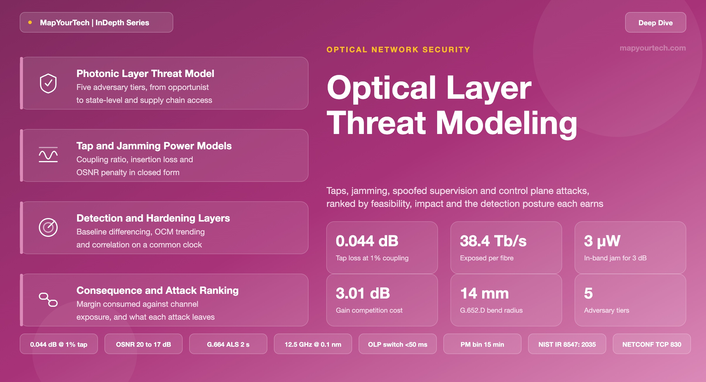
Optical Layer Threat Modeling: Taps, Jamming, Spoofed Supervision and Control Plane Attacks
A structured threat model for the photonic layer and its management plane, ranking attack classes by adversary capability, feasibility and blast radius, with the detection observable and hardening control each one deserves.
1. Introduction
A 1:99 optical splitter costs less than a patch cord, fits inside a handhole, and removes 0.044 dB from the line. That figure is not a vendor claim or a laboratory curiosity — it is arithmetic. Diverting 1% of the optical field leaves 99% in the fibre, and 10·log10(0.99) is −0.044 dB. Typical field OTDR splice-loss measurement uncertainty is a few hundredths of a decibel at best, and normal seasonal loss drift on a buried span exceeds 0.044 dB. The tap is not hidden by cleverness. It is hidden by measurement noise.
That single number frames the whole problem. Optical transport was engineered for availability and reach, and its instrumentation was designed to find faults — breaks, degradations, drifting amplifiers — not adversaries. An adversary who understands the instrumentation can operate inside its blind spots. Meanwhile the same transport layer now carries traffic whose confidentiality assumptions were formed when fibre was believed to be physically inaccessible. That assumption is obsolete. Cable landing station interception has been publicly documented, and the last four years have produced a steady record of deliberate physical interference with terrestrial and subsea fibre plant.
This article builds a threat model for the photonic layer and the management plane that drives it. A threat model is not a list of scary things. It is a structured mapping from adversary capability to attack class to observable to control. Each attack class is characterised by four properties: what physical or logical access it requires, what it costs the adversary in equipment and time, what it produces at the victim (loss of confidentiality, integrity, or availability), and — the property most often skipped — what measurable quantity changes when it happens. An attack with no observable is not undetectable in principle; it means no one has instrumented the right quantity.
1.1 Scope and Layer Boundaries
The scope here is the optical transport layer as defined by ITU-T G.872: the optical transmission section (OTS), the optical multiplex section (OMS), and the optical channel (OCh), plus the digital OTU and ODU layers that ride on them, plus the supervisory and management infrastructure that configures and monitors all of it. Client-layer security — Media Access Control Security (MACsec) per IEEE 802.1AE, IP Security (IPsec), Transport Layer Security (TLS) at the application — appears only where it interacts with optical-layer decisions. Passive optical network (PON) access threats are referenced for contrast but are not the focus; the point-to-point and meshed dense wavelength division multiplexing (DWDM) core is.
The layer boundary matters because it determines what an attack can and cannot reach. A transparent lightpath crossing five reconfigurable optical add-drop multiplexer (ROADM) nodes undergoes no electronic regeneration between its endpoints. Nothing in the middle inspects it, sanitises it, or re-frames it. Any perturbation of the optical field applied at hop three arrives at the far-end coherent receiver. That transparency is the reason optical bypass is economically attractive, and it is simultaneously the reason a local physical compromise has non-local consequences. The mechanism and the exposure are the same mechanism.
1.2 Why the Threat Model Is Different from an IT Threat Model
Three properties separate optical-layer threat modelling from conventional network security work.
The medium carries analogue state, not just bits. An IP packet either arrives or does not. An optical channel arrives with a power, an optical signal-to-noise ratio (OSNR), a polarisation state, a chromatic dispersion accumulation, and a nonlinear phase history. An adversary can change any of these without touching a single bit of framing, and the effect is graded rather than binary. Degradation attacks that sit 1 dB below the forward error correction (FEC) threshold produce no alarm and no traffic loss, but they consume the margin that protects the service against the next real fault.
The control plane and the transport plane share the fibre. The optical supervisory channel (OSC) rides the same cable as the traffic it supervises, typically as an out-of-band wavelength around 1510 nm or, in OpenROADM implementations, as a 1000BASE-LX wayside channel carrying management traffic, Link Layer Discovery Protocol (LLDP) topology information, and laser safety control signalling. Anything that reaches the fibre reaches the supervision. This is the structural difference from an enterprise network where the management plane can be physically separated from the data plane.
Safety systems are automation with a physical actuator. Automatic laser shutdown (ALS) and automatic power reduction (APR), specified in ITU-T G.664, exist to keep human eyes safe near a broken fibre. They are also a remotely triggerable mechanism for turning off a transmitter. Any input path into the ALS decision — a loss-of-signal indication, an OSC message, a management command — is an availability attack surface, because the correct behaviour of the safety system is to shut the laser down.
1.3 What the Model Ranks and Why
The ranking axis used throughout is feasibility × blast radius, not novelty. A published attack that requires a coherent receiver, a phase-locked local oscillator, and eight hours of undisturbed access to a manhole ranks below an authenticated Network Configuration Protocol (NETCONF) session with a stale credential, because the second one is reachable from a laptop and reconfigures the whole line system. Engineering attention follows the ranking, not the research literature's sense of what is interesting.
The output is a posture, not a product list. For each attack class the article names the physical mechanism, the boundary where the mechanism stops working, the observable that changes, the detection method that reads that observable, the realistic detection latency, and the hardening control that removes or shrinks the exposure. Where a control does not exist — and there are several — the article says so rather than substituting an aspiration.
Takeaway: The photonic layer's security properties follow from its engineering properties. Transparency gives optical bypass its economics and gives a local tap non-local reach. Analogue state gives coherent modulation its capacity and gives a degradation attack a place to hide below alarm thresholds. Shared-fibre supervision gives amplifier control its simplicity and puts the control plane inside the adversary's physical reach. Every exposure in this article is the shadow of a design decision that was correct on its own terms.
2. Documented Incidents and Prior Work
Threat models built on speculation age badly. This section anchors the model in what has actually been observed, separating documented incidents from experimental results and from theoretical analysis, because those three evidence classes carry different weight in a design decision.
2.1 Physical Interference with Fibre Plant
The record of deliberate physical interference with fibre infrastructure is now long enough to be treated as a design input rather than an outlier. In October 2022, coordinated cuts to fibre cables paralysed rail traffic across northern Germany. France experienced precise cuts to backbone cables linking Paris to Lyon, Strasbourg and Lille, disrupting internet service across several regions. Both events shared a characteristic that matters for defence: the attacker did not need to understand optics. They needed to know where the cable was and to cut more than one of them.
The subsea record is denser. Documented Baltic Sea incidents include damage to the Nord Stream pipelines in September 2022, the EE-S1 data cable in October 2023, the BCS East-West Interlink and C-Lion1 cables in November 2024, the Estlink 2 power cable in December 2024, and a Latvian State Radio and Television Centre fibre cable in January 2025. On 31 December 2025, the Finnish operator Elisa observed a significant data disruption on a fibre route between Helsinki and Tallinn; Finnish authorities took control of the vessel Fitburg and escorted it to port. Outside the Baltic, the PEACE submarine cable in the Red Sea suffered critical damage in October 2025, and the West Africa Cable System experienced disruptions affecting Cameroon and the Central African Republic in the same period.
Attribution remains genuinely contested, and the article does not resolve it. The Finnish Security and Intelligence Service publicly reassessed Baltic Sea cable investigations and found no evidence of deliberate Russian state activity, while U.S. legislative activity — the Undersea Cable Control Act passed by the House in September 2025 and the Strategic Subsea Cables Act of 2026 (S.3249, 119th Congress), which would require sanctions on foreign persons responsible for sabotage of critical undersea infrastructure — proceeds on a sabotage premise. What is not contested is the base rate. The International Cable Protection Committee reports that 150 to 200 subsea cable faults occur globally every year, the large majority from fishing gear, anchors and natural abrasion. As of April 2025, 597 subsea cables were in operation or under construction, carrying an estimated 99% of international data traffic.
Anchor drag and fishing gear cause most cable faults, and they produce the same OTDR signature as sabotage. A detection system that flags "cable damage" has not distinguished a threat from a trawler. Useful discrimination comes from correlation — vessel automatic identification system tracks, timing across multiple cables, whether the fault sits at a known survey point — not from the optical measurement alone. Designing the optical monitoring system as if it were an attribution system is the most common way to build an unusable alarm stream.
2.2 Interception at Scale
Passive interception of fibre traffic at cable landing stations has been publicly disclosed. The GCHQ Tempora programme, revealed in 2013, involved tapping fibre-optic cables and inspecting large volumes of transit traffic. The technical significance for a threat model is not the political question. It is the demonstration that interception at a landing station is an engineering problem that has been solved at scale by a well-resourced actor. Any confidentiality argument that rests on "nobody would go to the trouble" has a counterexample.
2.3 Experimental and Analytical Results
The research literature supplies the parameters the incident record does not. A 2026 survey of optical network security published in Electronics consolidates the current position and supplies several figures worth carrying forward.
For macro-bend tapping of standard single-mode fibre conforming to ITU-T G.652.D, the survey reports a critical bend radius of approximately 14 mm as the threshold at which usable light escapes the core, and recommends that operational monitoring flag any unexpected attenuation exceeding 3 dB as a possible tampering event. The 3 dB figure is a coarse threshold — it is an upper bound on how clumsy a tap has to be before conventional power monitoring notices, not a detection capability. A competent tap operates two orders of magnitude below it.
The same survey reports measured feasibility of passive attacks using 1:99 splitter insertion with negligible insertion loss and crosstalk, and confirms that such attacks leak usable signal from all channels on a WDM link with minimal disturbance. For active attacks, controlled experiments have verified that localised, near-receiver interference substantially deteriorates throughput and stability in realistic setups — establishing jamming as an operational technique rather than a theoretical model. The survey identifies ROADM and wavelength selective switch (WSS) nodes, and spans traversing erbium-doped fibre amplifiers (EDFAs), as the points of highest sensitivity, because filter isolation, gain equalisation and channel loading all have to be balanced against resilience to hostile power excursions.
Earlier foundational work established the tap mechanism taxonomy that the field still uses — fibre bending, optical splitting, evanescent coupling, scattering, and V-groove coupling — and noted that most of these require altering the physical characteristics of the fibre. That constraint is the root of every detection method discussed in remote fibre test systems used in managed optical fibre networks: if the adversary must change the fibre, the fibre can be interrogated for the change.
2.4 Standards Coverage and Its Gaps
Optical transport standards address security unevenly, and knowing where the coverage stops is more useful than knowing where it exists.
| Standard | What it specifies | Security relevance | Gap it leaves |
|---|---|---|---|
| ITU-T G.872 | Optical transport network architecture: OTS, OMS, OCh, ODU and OTU layering | Defines the layer boundaries a threat model needs | Architecture only; no adversary model |
| ITU-T G.709 | OTN interfaces, frame structure, general communication channels (GCC0/1/2), trail trace identifier | GCC provides an in-band management path; TTI provides path identification | TTI is an identifier, not an authenticator — it is plaintext and forgeable |
| ITU-T G.874 | OTN element management: fault, configuration, performance and security management | Names security management as a management function | Specifies the management model, not cryptographic mechanisms |
| ITU-T G.664 | Optical safety procedures: ALS and APR, restart pulse timing | The safety automation that an availability attack can drive | Written against accidental fibre breaks, not adversarial LOS injection |
| ITU-T G.873.1 | Linear OTN protection; APS channel in ODUk overhead | Protection switching restores availability after a cut | APS bytes are unauthenticated overhead |
| ITU-T G.7712 | Data communication network architecture for transport management | Defines the DCN that carries control traffic | DCN isolation is an operator design choice, not a mandate |
| IEC 60825-1 / 60825-2 | Laser product safety classification and hazard levels | Bounds the optical power an attacker can legitimately encounter | Safety framing; power injection by an attacker is out of scope |
| IEEE 802.1AE (MACsec) | Hop-by-hop Ethernet frame confidentiality and integrity | The most widely deployed real countermeasure to tapping | Client layer; leaves optical overhead and OSC in the clear |
| IETF RFC 6241 (NETCONF) | Configuration protocol over SSH, TCP port 830 | The transport for most optical management today | Mandates a secure transport; does not mandate how credentials are managed |
| NIST FIPS 203 / 204 / 205 | ML-KEM, ML-DSA and SLH-DSA post-quantum algorithms | The replacement set for key establishment and signatures | Standards exist; optical vendor implementation status varies widely |
Read the Full Analysis with Premium
The remaining 88% of this article — the design numbers, trade-offs and field guidance — is part of MapYourTech Premium, along with the full premium library, courses and professional tools.
You May Also Like
-
Free
-
August 31, 2026
-
Free
-
August 27, 2026