
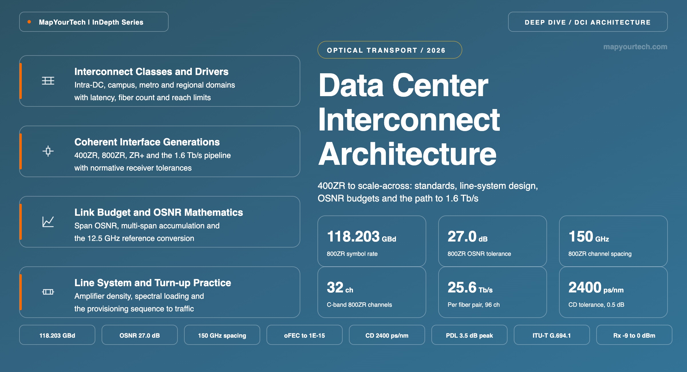
Data Center Interconnect Architecture: 400ZR to Scale-Across
How DCI transport moved from purpose-built transponder shelves to router-hosted coherent pluggables, and what the AI scale-across requirement changes next.
The best network design is one that anticipates tomorrow's needs.
What You Will Learn
- Separate the three data center interconnect distance classes — campus below 10 km, metro 10–120 km, long-haul above 120 km — and map each to its transport option in Table 1.
- Quote the OIF 800ZR normative optical parameters from memory: 118.203 GBd DP-16QAM with oFEC, 27.0 dB/12.5 GHz receiver OSNR tolerance, and a 32-channel plan on 150 GHz spacing.
- Place every element of the IP-over-DWDM signal path in Figure 4, from the router faceplate through the add filter, booster, in-line amplifier and drop filter to the far-end receiver.
- Compute a span OSNR from launch power, span loss and amplifier noise figure, and reproduce the worked result of 35.0 dB over one 80 km span and 29.0 dB over four.
- Convert between electrical SNR and 12.5 GHz reference OSNR for a 118.203 GBd carrier, and show why the 9.75 dB offset decides whether a link closes.
- Derive per-fiber capacity from a channel plan: 32 × 800 Gb/s on 150 GHz gives 25.6 Tb/s across the C-band at a spectral efficiency of 5.33 b/s/Hz.
- Select a transport option with the decision sequence in Figure 6, from single-span ZR through extended-reach ZR+ to embedded coherent and full-spectrum transponders.
- Anchor the 2026 roadmap to published dates: the 1600ZR Implementation Agreement due in the second quarter of 2026 and 1600ZR+ in the third.
1. Introduction
Data center interconnect is the transport layer that carries traffic between data centers, and it is now the largest single consumer of coherent optical hardware. The Optical Internetworking Forum published the 400ZR Implementation Agreement in April 2020 for amplified point-to-point DWDM links of 120 km or less, plus an unamplified single-wavelength application with an 11 dB loss budget; that one document moved a 400 Gb/s coherent wavelength out of a transponder shelf and into a router faceplate. Six years later the same architecture carries 800 Gb/s, and the market research firm Cignal AI forecast more than 200,000 shipments of 800ZR and 800ZR+ modules during 2026 — an analyst projection, not a shipment record.
The reason the volume moved is economic rather than optical. A 400G coherent pluggable in a QSFP-DD or OSFP port presents both the client function and the coherent line interface in a single module, so the separate transponder shelf, its client optics and its framing electronics all disappear from the bill of materials and from the power budget. That collapse is examined end to end in the MapYourTech walkthrough of IP-over-DWDM architecture, and the rack-level arithmetic behind it in the analysis of power per bit for router-hosted optics.
What changed in 2025 and 2026 is the demand side. AI training clusters outgrew the power and floor space available at a single site, so the compute fabric now spans buildings, campuses and in some designs entire regions. Nokia describes this third scaling dimension as scale-across networking: a specialized form of DCI for the back-end network that lets an XPU cluster extend beyond one building, connecting accelerators across tens, hundreds or potentially thousands of kilometres. Traffic that used to be a fabric problem inside one hall becomes a coherent transport problem between halls, and the latency of the optical path becomes part of the training loop.
This article covers the DCI transport layer as an engineering discipline. Section 2 partitions the problem by distance and service class. Section 3 works through the coherent interface generations and their normative parameters. Section 4 builds the line system that carries them. Section 5 is the quantitative core: span OSNR, multi-span accumulation, reference-bandwidth conversion and penalty allocation, with worked numbers. Sections 6 through 9 cover design trade-offs, turn-up practice, monitoring and fault isolation. Sections 10 through 12 compare the alternatives, set out the roadmap to 1.6 Tb/s, and collect the specifications, formulas and standards in one reference block.
Takeaway: DCI is no longer a niche application of telecom transport. It is the volume driver for coherent optics, and its design constraints — cost per bit, power per bit, faceplate density and now training-loop latency — are what set the direction of the whole optical transport industry.
2. Interconnect Classes and Design Drivers
Data center interconnect divides into three distance classes, and each one has a different binding constraint. Campus DCI runs below about 10 km and is loss-limited rather than noise-limited, so the design question is connector and patch-panel budget rather than amplifier noise. Metro DCI runs 10–120 km on a single amplified span and is the exact application the ZR interface family was written for. Long-haul DCI runs beyond 120 km across multiple amplified spans and usually across ROADM nodes, which is where extended-reach modes and embedded coherent engines take over.
Overlaid on that distance axis is a service axis borrowed from the compute side. Scale-up interconnects accelerators inside one rack over links of a few metres, dominated by copper today with rising per-lane rates pushing toward optics. Scale-out extends the cluster across racks inside one building over hundreds of metres to a few kilometres, using direct-detect pluggables. Scale-across is the newest term and the one that matters here: it is DCI applied to the back-end network, carrying collective traffic between sites so that a cluster can exceed the gigawatts and floor space a single building can supply.
Latency as a Design Constraint
Two different latency requirements govern DCI, and confusing them produces bad designs. The older one comes from cloud availability engineering: synchronous replication between availability domains in one region requires that total round-trip latency at the application layer stay within a few milliseconds, and once switching, serialization, buffering and application read and write times are subtracted, the budget left for fiber time-of-flight is a few hundred microseconds. That is the arithmetic that fixed the classic metro DCI radius at under 100 km.
The newer requirement comes from distributed training. Most large language models in production are trained synchronously: every accelerator receives data in parallel and waits for all other nodes to finish before updates are aggregated, so a single delayed node costs wall-clock time across the whole job. Views presented at OFC 2026 put the practical scale-across radius at approximately 50 km for inference, around 100 km for synchronous training, and beyond 5,000 km for asynchronous training — conference-panel estimates that varied between speakers, not standard-specified limits. Asynchronous techniques relax the constraint by design, which is why the same operators who need 100 km links for one workload are also buying thousand-kilometre routes for another.
Read the Full Analysis with Premium
The remaining 88% of this article — the design numbers, trade-offs and field guidance — is part of MapYourTech Premium, along with the full premium library, courses and professional tools.
You May Also Like
-
Free
-
August 25, 2026

-
Free
-
August 22, 2026

-
Premium
-
August 22, 2026