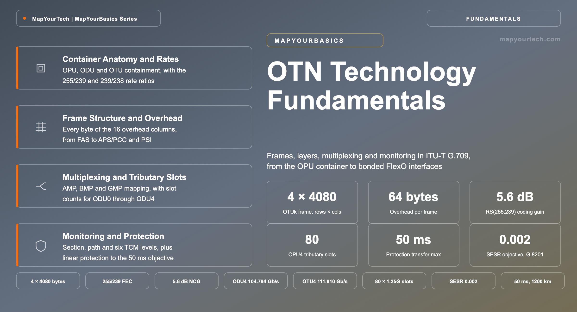
OTN Technology Fundamentals: Frames, Layers and Standards
How ITU-T G.709 wraps any client signal in a fixed frame, adds error correction and six layers of monitoring, and carries it across multiple operator domains.
What is not monitored is not maintained.
What You Will Learn
- Define the OPU, ODU and OTU containers from the containment relationship of Figure 1, and state which overhead each layer adds.
- Place every overhead field in the 4 × 4080 byte OTUk frame of Figure 4, from the six FAS bytes to the 256 FEC columns.
- Convert a client rate into a container rate using the 255/239 and 239/238 ratios of Table 2, and check 104,355,975 kb/s of OPU4 payload against a 103,125,000 kb/s client.
- Size a client into 1.25 Gb/s tributary slots using Table 4, and select between AMP, BMP and GMP for a given client.
- Quantify what RS(255,239) delivers: 6.7% overhead, 5.6 dB net coding gain at 1 × 10⁻¹², and a 1,024-bit burst-correction depth.
- Assign section, path and the six tandem connection monitoring levels across a multi-operator path using the nesting rules of Figure 11.
- Anchor a service contract to the 27,500 km objectives of ITU-T G.8201 — SESR 0.002 and BBER 2.5 × 10⁻⁶ — and to the 50 ms protection transfer time of ITU-T G.873.1.
- Read a beyond-100G interface stack, from OTUCn and its 105,258,138 kb/s per-instance rate through the FlexO groups of the ITU-T G.709.x series.
1. Introduction
A 100 Gb/s Ethernet port on a router in Frankfurt and the matching port in Singapore are connected by fibre that crosses four operator networks, two subsea segments and perhaps thirty optical amplifiers. The Ethernet frames themselves carry no field that says which of those segments introduced an error, and no field that lets an operator prove the path met its contract last month. The Optical Transport Network supplies both. It takes the client signal exactly as it arrives, wraps it in a fixed-size frame with dedicated overhead bytes, adds a forward error correction block, and hands the result to a wavelength. Everything the client sent comes out the far end bit-for-bit identical; everything the network needs to manage the connection travels beside it.
Standardised in the ITU-T G.709/Y.1331 Recommendation, OTN replaced SDH and SONET as the framing layer of long-haul and metro optical transport for one structural reason: it separates the client from the transport. SDH multiplexing assumed the client was a synchronous byte stream and imposed network-wide timing to carry it. OTN maps a client of any protocol, at any rate within its container range, and adds justification overhead so that the client clock and the container clock stay independent. That single design decision is why a G.709 network carries STM-64, 10 Gigabit Ethernet, Fibre Channel, and another operator's ODU2 through the same hardware, and why the industry signal flow from router port to router port passes through the same three containers regardless of what sits on either end.
The technology solves four problems that direct wavelength transport leaves open. Error correction extends unregenerated reach without touching the optical line design. Digital multiplexing packs several sub-rate clients onto one expensive wavelength. Layered overhead makes each network segment independently monitorable, which is what allows a fault to be localised to one operator rather than to a continent. And standardised protection switching restores traffic on an alternate path inside a defined transfer time. Those four functions define where OTN belongs: on any link where the wavelength is shared, crosses a management boundary, or carries a service with a written availability commitment.
This article covers the OTN digital layer end to end at a level a working engineer can apply directly — the containers and their bit rates, the frame and its overhead fields, the multiplexing and mapping procedures, the FEC, the monitoring hierarchy, protection, error performance objectives, and the OTUCn and FlexO structures that carry rates above 100 Gb/s. The optical line engineering underneath — amplifier cascades, dispersion, nonlinear interference — sits outside its scope, as does the control plane above it.
2. Optical Data Unit Definition and Container Anatomy
An optical data unit is an information structure consisting of an optical payload unit together with the overhead that supervises the end-to-end path carrying it. The optical payload unit holds the client signal plus the overhead needed to adapt the client rate to the container rate. The optical transport unit is the optical data unit plus section overhead and a forward error correction area, and it is the structure a wavelength transmits.
Those three names describe one nested object rather than three separate signals. Figure 1 shows the containment: the client sits inside the OPU, the OPU sits inside the ODU, the ODU sits inside the OTU. Each layer adds its own overhead at the point where it is assembled and removes it at the point where it is disassembled, and that assembly boundary is what defines the layer's reach. OPU overhead is inserted where a client enters the network and removed where it leaves. ODU overhead travels the whole path between the two service endpoints. OTU overhead is inserted and terminated at every 3R regeneration point, so it covers one section of the path and no more.
2.1 Adjacent Quantities and Their Distinctions
Three pairs of terms account for most of the confusion a newcomer meets, and each pair separates cleanly once the containment picture is fixed.
ODU against OTU. The ODU is a path-layer structure that survives across the whole connection; the OTU is a section-layer structure that is rebuilt at every regeneration point. A cross-connect switches ODUs and never switches OTUs, because switching an ODU means terminating the OTU on the incoming side, moving the ODU, and generating a fresh OTU with fresh FEC on the outgoing side.
OPU payload rate against client rate. The OPU payload area runs slightly faster than the client it carries, and the difference is deliberate. A 100GBASE-R client runs at 103,125,000 kb/s while the OPU4 payload area runs at 104,355,975.33 kb/s (both standard-specified, IEEE 802.3 and ITU-T G.709 Table 7-3). The 1,230,975 kb/s difference is the headroom that justification overhead uses to absorb the client's frequency offset without buffer overflow.
Higher-order ODU against lower-order ODU. These are roles rather than structures. An ODU2 carrying an Ethernet client directly is a lower-order ODU. The same ODU2 carrying eight multiplexed ODU0s is a higher-order ODU. The frame is identical; what changes is whether the OPU payload holds a client or holds other ODUs.
2.2 Units and the Container Rate Arithmetic
Container rates in G.709 are stated as an exact rational multiple of a base rate, never as a rounded decimal, because the ratio itself encodes how much overhead the layer adds. Every OTN rate calculation reduces to one line:
OTUk = 255/239 × ODUk and ODUk = 239/238 × OPUk payloadWhere:
- 255/239 — the OTU expansion: 255 bytes leave the encoder for every 239 that enter it, so the FEC area adds 6.69% to the line rate
- 239/238 — the ODU expansion: one overhead column added for every 238 payload columns in the frame row
- k — the container index, 0 through 4, identifying the approximate rate: 1.25, 2.5, 10, 40 and 100 Gb/s
- Typical range: ODU0 at 1,244,160 kb/s through ODU4 at 104,794,445.815 kb/s (standard-specified, ITU-T G.709 Table 7-2)
Practical Example — from a 100GBASE-R client to an OTU4 line rate. Start at the SDH base rate the hierarchy is anchored to, 99,532,800 kb/s. The ODU4 rate is 239/227 × 99,532,800 = 104,794,445.815 kb/s. The OTU4 rate is 255/239 × 104,794,445.815 = 111,809,973.568 kb/s, which is the same as 255/227 × 99,532,800. The client at 103,125,000 kb/s therefore occupies 98.8% of the 104,355,975.33 kb/s OPU4 payload area, and the line runs 8.4% above the client rate once section overhead and FEC are added.
Takeaway: OPU, ODU and OTU are one nested object, not three signals. The layer boundary is the point where that layer's overhead is inserted and extracted, and that boundary — adaptation, path, section — is what determines how far each layer's supervision reaches.
3. Transport Framing Evolution and the OTN Requirement
A plesiochronous hierarchy multiplexes tributaries whose clocks are nominally equal but independently generated, and absorbs the difference by inserting stuffing bits at each multiplexing stage. Nothing in the aggregate signal records where a given tributary sits, so reaching one 2 Mb/s circuit inside a 140 Mb/s aggregate meant demultiplexing all three intermediate stages and rebuilding them afterwards. Every drop point therefore carried a stack of back-to-back multiplexers, and because line codes and optical interfaces were left to the manufacturer, the equipment at both ends of a span had to come from the same supplier.
Synchronous multiplexing removed both problems. SDH and SONET locked every tributary to a common network clock and gave each one a fixed, addressable position in the frame, so an add-drop multiplexer reached a single circuit without touching the rest. Standard optical interfaces at the network node interface made equipment from two suppliers interwork, section, line and path overhead gave the first structured supervision of a transport signal, and automatic protection switching delivered a 50 ms restoration objective. Three constraints came with it. The whole network had to stay synchronised. The container assumed a synchronous byte-stream client, so an Ethernet or Fibre Channel signal was adapted into it rather than carried through it, and the client’s own timing did not survive the trip. And supervision came in exactly three fixed levels, none of which could be assigned to an arbitrary segment of a path — which meant that a circuit crossing three operators produced one error count and no way to say whose network produced it.
Wavelength division multiplexing then multiplied capacity per fibre without touching either problem, and added one of its own. A wavelength carries no overhead of its own: the operator sees the fibre underneath it and the client signal inside it, and has no digital entity in between to monitor, protect or hand off at a boundary. Reading the client’s overhead to supervise the wavelength means terminating the client, which defeats the transparency the wavelength was bought for. By the late 1990s a single fibre was carrying SDH, Gigabit Ethernet, Fibre Channel and ESCON on separate wavelengths, each needing its own adaptation, and none of them managed as an optical channel.
3.1 The Four Requirements OTN Answered
Client transparency with clock independence. The OPU carries the client bit-for-bit and runs slightly faster than it, with justification overhead absorbing the frequency difference. The client’s clock is reconstructed at the far end from that justification information rather than from a network reference, so the container never imposes synchronisation on the service it carries. GMP later generalised this to any client rate below the payload rate.
Error correction inside the frame. The 256 FEC columns give 5.6 dB of net coding gain at an output error ratio of 1 × 10⁻¹² (standard-specified, ITU-T G-series Supplement 39). That gain converts directly into unregenerated reach or into relaxed optical specifications, and it belongs to the framing layer rather than to the line system, so a link gains it by changing transponders rather than by re-engineering the amplifier chain.
Supervision assignable to any segment. Section and path monitoring cover the two extremes; the six tandem connection levels cover everything between them, including segments defined by a commercial boundary rather than by an equipment boundary. An operator can therefore be held to a per-segment error count on a path it does not own end to end, which is the function no earlier framing layer provided.
Digital multiplexing onto a wavelength. Tributary slots let several sub-rate services share one expensive wavelength while each keeps its own containers, its own overhead and its own monitoring. A 100 Gb/s wavelength carrying ten 10 Gb/s services reports ten independent error counts rather than one.
One capability was left out deliberately. OTN does not multiplex statistically: a tributary slot is reserved whether or not the client is sending, and the wrapper costs a fixed 7.1% of the line rate. That trade — guaranteed capacity and bit-level accounting against zero statistical gain — is what sections 15 and 16 return to, and it is the reason a wavelength inside one administrative domain may be better off without an OTN layer at all. The wider architectural context is developed in the MapYourTech comprehensive study of the optical transport network.
Takeaway: OTN exists because a wavelength is not a managed entity and SDH could not carry an arbitrary client without terminating its timing. The digital wrapper supplied four things at once — transparency, in-frame FEC, segment-assignable supervision and digital multiplexing — and the container and overhead model that delivered them in 2001 is unchanged at 800 Gb/s.
4. OTU Frame Structure and Overhead Allocation
The OTUk frame is an octet-based block of 4 rows by 4080 columns, transmitted left to right and top to bottom, most significant bit first. Columns 1 to 14 hold frame alignment and OTU overhead, columns 15 and 16 hold OPU overhead, columns 17 to 3824 hold the payload, and columns 3825 to 4080 hold forward error correction. The dimensions never change. An OTU1 frame and an OTU4 frame contain exactly the same 16,320 bytes; only the clock differs, so the frame period falls from 48.971 µs at OTU1 to 1.168 µs at OTU4 (standard-specified, ITU-T G.709 Table 7-4).
That fixed geometry is the practical reason OTN silicon scales cleanly across rates. A framer built for one container parses another by changing a clock divider rather than a parser. The OTUCn, OTU25 and OTU50 signals break the pattern in one respect: their frames are 4 rows by 3824 columns with no FEC area, because at those rates the error correction is interface specific and lives in the physical interface specification rather than in G.709 itself.
4.1 Frame Alignment and Section Monitoring
The frame alignment signal occupies row 1, columns 1 to 6, and carries the fixed pattern OA1 repeated three times followed by OA2 repeated three times, with OA1 equal to 1111 0110 and OA2 equal to 0010 1000 (standard-specified, ITU-T G.709 clause 15.6.2.1). A receiver hunts for that pattern to establish byte and frame boundaries, and loss of frame alignment is the first defect declared when a link degrades past the point of recovery. Row 1 column 7 holds the multiframe alignment signal, a byte that increments once per frame and so defines a 256-frame multiframe. Overhead signals longer than one byte — the trail trace identifier, the tandem connection activation field, the payload structure identifier — use that counter to lock their own multiframe to the frame stream.
Section monitoring occupies row 1, columns 8 to 10. Those three bytes carry a trail trace identifier for connectivity verification, a bit interleaved parity byte computed over the previous frame's payload, and backward error and defect indications that report the far end's view back to the near end. The general communication channel GCC0 in row 1, columns 11 and 12 gives the two section endpoints a clear data channel between them. Column 13 carries the optional synchronisation message channel, which transports synchronisation status and precision time protocol messages inside the frame itself, and column 14 is reserved. The ODU layer adds two further communication channels, and the distinction between GCC0, GCC1 and GCC2 comes down to which layer terminates each one.
4.2 Path, Tandem Connection and Adaptation Fields
Path monitoring sits in row 3, columns 10 to 12, and carries the same field set as section monitoring — TTI, BIP-8, BEI and BDI — applied end to end rather than section by section. The six tandem connection monitoring fields occupy row 2 columns 5 to 13 and row 3 columns 1 to 9, three bytes each, and row 2 column 3 adds one delay measurement bit for the path monitor plus one for each of the six tandem connection levels. Row 4 carries the two ODU communication channels in columns 1 to 4, the four-byte automatic protection switching and protection communication channel in columns 5 to 8, and reserved bytes in columns 9 to 14. Four further bytes — row 2 columns 4 and 14, and row 3 columns 13 and 14 — are set aside for experimental use inside a single operator’s subnetwork, with no requirement to forward them beyond it. Equipment provisioned against earlier editions may still report a fault type and fault location byte at row 2, column 14, where the current allocation is experimental overhead.
Columns 15 and 16 belong to the OPU. In row 4, column 15 holds the payload structure identifier, a 256-byte multiframed structure whose first byte is the payload type — the code that tells the far end whether the payload is a bit-stream client, a GFP-framed client, or a multiplex of lower-order ODUs. Column 16 in row 4 holds the negative and positive justification opportunity bytes for asynchronous mapping. Rows 1 to 3 of columns 15 and 16 carry the justification control bytes whose meaning depends on the mapping procedure in use.
| Field | Layer | Location (row, column) | Bytes | Function |
|---|---|---|---|---|
| FAS | OTU | 1, 1–6 | 6 | Frame boundary recovery from the fixed OA1/OA2 pattern |
| MFAS | OTU and ODU | 1, 7 | 1 | 256-frame multiframe counter for multiframed overhead |
| SM | OTU | 1, 8–10 | 3 | Section TTI, BIP-8, BEI and BDI between 3R points |
| GCC0 | OTU | 1, 11–12 | 2 | Clear channel between OTU termination points |
| OSMC | OTU | 1, 13 | 1 | Optional channel carrying SSM, eSSM and PTP messages in-frame |
| RES | OTU | 1, 14 | 1 | Reserved for future standardisation, set to all-0s |
| RES | ODU | 2, 1–2 | 2 | Reserved for future standardisation, set to all-0s |
| PM&TCM | ODU | 2, 3 | 1 | Delay measurement bits: one for the path, one per TCM level |
| TCM6 to TCM4 | ODU | 2, 5–13 | 9 | Three of the six tandem connection monitoring levels |
| TCM3 to TCM1 | ODU | 3, 1–9 | 9 | The remaining three tandem connection levels |
| PM | ODU | 3, 10–12 | 3 | End-to-end path TTI, BIP-8, BEI and BDI |
| EXP | ODU | 2, 4 and 14; 3, 13–14 | 4 | Experimental use inside one operator’s own subnetwork |
| GCC1 and GCC2 | ODU | 4, 1–4 | 4 | Clear channels between ODU path termination points |
| APS/PCC | ODU | 4, 5–8 | 4 | Protection switching protocol, one channel per monitoring level |
| RES | ODU | 4, 9–14 | 6 | Reserved for future standardisation, set to all-0s |
| PSI | OPU | 4, 15 | 1 | Payload type and mapping-specific structure identifier |
| JC, NJO | OPU | 1–4, 15–16 | Varies | Justification control for rate adaptation |
| FEC | OTU | 1–4, 3825–4080 | 1,024 | Reed-Solomon RS(255,239) parity, 16 interleaved codecs per row |
The APS/PCC field is four bytes wide but carries eight independent protection channels. Bits 6 to 8 of the MFAS byte select which channel the current frame's APS bytes belong to, giving one channel for the ODU path, six for the tandem connection levels, and one for sub-network connection protection with inherent monitoring. A protection scheme configured at the wrong monitoring level therefore reads a different channel than its peer and never completes the protocol handshake.
Takeaway: 64 overhead bytes per frame, in fixed positions that never move between rates, carry every management function OTN provides. Knowing which row and column a field occupies is what turns an alarm printout into a fault location.
5. Container Types, Bit Rates and Client Mapping
Nine ODU container types cover the deployed rate range from 1.25 Gb/s to multiple terabits per second. Five of them — ODU0, ODU1, ODU2, ODU3 and ODU4 — are fixed-rate containers anchored to the SDH hierarchy, so their rates are exact rational multiples of 1,244,160 kb/s. ODU2e is a variant sized for bit-transparent 10 Gigabit Ethernet. ODU25 and ODU50 target 5G transport and metro applications at rates matched to Ethernet 25GBASE-R and 50GBASE-R optics. ODUCn scales in units of about 100 Gb/s for rates above 100 Gb/s. ODUflex is the container whose rate is set by the client rather than by the standard.
The clock tolerance in Table 2 matters more than it looks. A 20 ppm container and a 100 ppm container demand different justification headroom, and a mapper sized for the tighter tolerance will overflow on the looser client. That is why ODUflex carrying constant-bit-rate clients is specified at 100 ppm even when the client itself holds 20 ppm: the maintenance signals that replace the client during a fault run at the looser tolerance, and the container has to carry those too. Container clocking, jitter and wander behaviour is a design area in its own right, treated separately in the MapYourTech material on OTN clock and synchronization.
| Container | ODU rate (kb/s) | OTU rate (kb/s) | Tolerance (ppm) | Primary client |
|---|---|---|---|---|
| ODU0 / OTU0 | 1,244,160.000 | 1,327,451.046 | 20 | 1000BASE-X Gigabit Ethernet |
| ODU1 / OTU1 | 2,498,775.126 | 2,666,057.143 | 20 | STM-16, OC-48 |
| ODU2 / OTU2 | 10,037,273.924 | 10,709,225.316 | 20 | STM-64, transcoded 10GBASE-R |
| ODU2e | 10,399,525.316 | — | 100 | Bit-transparent 10GBASE-R |
| ODU3 / OTU3 | 40,319,218.983 | 43,018,413.559 | 20 | STM-256, 40GBASE-R |
| ODU4 / OTU4 | 104,794,445.815 | 111,809,973.568 | 20 | 100GBASE-R |
| ODU25 / OTU25 | 26,409,711.013 | 26,409,711.013 | 20 | 25GBASE-R, 5G fronthaul and midhaul |
| ODU50 / OTU50 | 52,819,422.026 | 52,819,422.026 | 20 | 50GBASE-R, metro aggregation |
| ODUCn / OTUCn | n × 105,258,138.053 | n × 105,258,138.053 | 20 | 200GBASE-R and above, multiplexed ODUk |
| ODUflex | 239/238 × client rate | — | 100 | Any CBR or packet client without a fixed container |
Every OTUk line rate sits 6.69% above its ODU, and that increment is the FEC. The OTU25, OTU50 and OTUCn rows show the same rate in both columns because those signals carry no FEC area inside the G.709 frame — their error correction belongs to the interface specification that carries them.
| Container | OPU payload (Gb/s) | OTU line rate (Gb/s) | Total expansion (%) |
|---|---|---|---|
| ODU0 / OTU0 | 1.239 | 1.327 | 7.1 |
| ODU1 / OTU1 | 2.488 | 2.666 | 7.1 |
| ODU2 / OTU2 | 9.995 | 10.709 | 7.1 |
| ODU3 / OTU3 | 40.151 | 43.018 | 7.1 |
| ODU4 / OTU4 | 104.356 | 111.810 | 7.1 |
The expansion column is constant at 7.1% because the ratio 255/238 governs every fixed-rate container: 16 FEC bytes and one overhead column added for every 238 payload columns. A planner sizing a line system therefore treats the OTN wrapper as a fixed 7.1% tax on payload, applied identically at every rate.
5.1 Mapping Procedures: AMP, BMP and GMP
Getting a client into an OPU payload area requires a rate adaptation method, and G.709 defines three. Bit-synchronous mapping locks the OPU clock to the client clock, adds no justification, and is used where the transport equipment can derive its transmit clock from the incoming client. Asynchronous mapping runs the two clocks independently and adjusts by a single byte per frame using the negative and positive justification opportunity bytes, which suits clients whose rate sits close to the container's payload rate. Generic mapping procedure distributes a computed number of client bytes across the payload area on every frame and signals that count in the justification control bytes, which lets one mechanism cover any client rate below the container's payload rate.
GMP is the procedure that made OTN a general transport container rather than an SDH replacement. Because the mapper transmits an explicit count of client bytes per frame, the ratio between client and container rates can be anything, and the demapper reconstructs the client clock from that count. Every container above ODU2 relies on it, and every client that is not an exact rational fraction of its container uses it.
Choosing between the three procedures comes down to two questions: whether the container clock can be locked to the client clock, and whether the client can ever run faster than the payload area allocated to it. Figure 6 sets the four methods side by side with their clock relationship, justification mechanism, overhead usage and payload type code. Note the payload type column in particular — a mismatch there is the first thing to check when a newly provisioned circuit raises a payload mismatch defect.
| Client signal | Client rate (kb/s) | Container | Mapping |
|---|---|---|---|
| 1000BASE-X | 1,250,000 | ODU0 | GMP with timing-transparent transcoding |
| STM-16 / OC-48 | 2,488,320 | ODU1 | AMP or BMP |
| STM-64 / OC-192 | 9,953,280 | ODU2 | AMP or BMP |
| 10GBASE-R, transcoded | 10,312,500 | ODU2 | GFP-F or 1027/1024 transcoding with GMP |
| 10GBASE-R, bit transparent | 10,312,500 | ODU2e | BMP |
| 25GBASE-R | 25,781,250 | ODU25 | GMP |
| 40GBASE-R | 41,250,000 | ODU3 | 1027/1024 transcoding with GMP |
| 100GBASE-R | 103,125,000 | ODU4 | 1027/1024 transcoding with GMP |
| Fibre Channel FC-800 | 8,500,000 | ODUflex(CBR) | BMP |
| 400GBASE-R | 425,000,000 | ODUflex(IMP) in ODUCn | Idle mapping procedure with GMP |
Takeaway: Container choice follows client rate, and mapping procedure follows the relationship between the two clocks. GMP removed the constraint that a client had to be a rational fraction of its container, which is the reason a single OTN platform carries Ethernet, SDH and Fibre Channel through the same silicon.
6. Multiplexing Hierarchy and Tributary Slot Allocation
A client signal reaches a wavelength by one of two routes. In the direct route it is mapped into an OPU, the OPU into an ODU, the ODU into an OTU, and the OTU onto an optical tributary signal. In the multiplexed route the lower-order ODU is first mapped into an optical data tributary unit, several tributary units are byte-interleaved into a tributary unit group, and that group becomes the payload of a higher-order OPU which then follows the direct route. Figure 7 traces both.
6.1 Tributary Slot Granularity
The higher-order OPU payload area is divided into tributary slots, each a fixed fraction of the payload interleaved byte by byte across the frame. Two granularities exist in the ODUk hierarchy: an approximately 2.5 Gb/s slot, and an approximately 1.25 Gb/s slot that divides the same payload into twice as many. OPU2 and OPU3 ports that support the finer granularity must also support the coarser one, because a port operating in 2.5 Gb/s mode pairs slots i and i + n to form one coarse slot and so interworks with older equipment. The OPUCn uses a third granularity, an approximately 5 Gb/s slot, twenty per OPUC instance.
Each tributary slot carries its own overhead, frame-interleaved into the OPU overhead columns. An OPU2 2.5 Gb/s slot gets its overhead once every four frames; a 1.25 Gb/s slot once every eight; an OPUC 5 Gb/s slot once every twenty. That multiframe period is why the multiframe alignment counter exists, and why a container with more slots takes longer to deliver a complete slot-overhead cycle.
| Container | 1.25 Gb/s slots | 2.5 Gb/s slots | Slot rate (kb/s) | MSI length |
|---|---|---|---|---|
| OPU1 | 2 | — | 1,244,160 | 2 bytes |
| OPU2 | 8 | 4 | 1,249,410 | 4 or 8 bytes |
| OPU25 | 20 | — | 1,314,961 | 20 bytes |
| OPU3 | 32 | 16 | 1,254,704 | 16 or 32 bytes |
| OPU50 | 40 | — | 1,314,961 | 40 bytes |
| OPU4 | 80 | — | 1,304,450 | 80 bytes |
| OPUC (each instance) | — | 20 at 5 Gb/s | 5,240,886 | 20 bytes per instance |
Slot rates in Table 5 are the payload rate divided by the slot count, so they differ slightly between containers even though all are nominally 1.25 Gb/s. That difference is why a client sized to fill an OPU2 slot exactly does not fill an OPU4 slot exactly, and why the number of slots a given ODU needs is a per-container answer rather than a single number.
The number of slots a client consumes follows from the ratio of its ODU rate to the slot rate of the container carrying it, and the mapping procedure follows from whether that route needs negative justification. Figure 9 collects both for every standardised route: an ODU2 takes 8 of the 80 slots in an OPU4 and 4 of the 32 in an OPU3, and only four routes — ODU0 into ODU1, ODU1 into ODU2, ODU1 into ODU3, and ODU2 into ODU3 — use asynchronous mapping. Every other route uses GMP.
Slot count sets the practical limit on how many services one wavelength carries, not the raw bit rate. An OPU4 holds 80 ODU0 services or 10 ODU2 services, and a service that needs 1.4 Gb/s consumes two slots rather than one, stranding 1.2 Gb/s. Sizing an aggregation node from total bandwidth alone therefore understates the container count needed, sometimes by 30% or more where the service mix has many small, awkwardly sized clients.
Takeaway: Multiplexing packs several ODUs into one wavelength through a fixed grid of tributary slots, and the granularity of that grid — 1.25, 2.5 or 5 Gb/s — sets how efficiently an arbitrary service mix fills the container.
7. Forward Error Correction in the OTU Layer
The 256 FEC columns of the OTUk frame carry Reed-Solomon RS(255,239) parity, a hard-decision block code operating on 8-bit symbols over GF(256). Each OTUk row of 4080 bytes is divided into 16 interleaved sub-rows of 255 bytes, and each sub-row is one code word: 239 information bytes followed by 16 parity bytes. Four rows therefore hold 64 code words per frame. The code corrects up to eight symbol errors per code word, and because the 16 code words in a row are byte-interleaved, a burst of up to 1,024 consecutive corrupted bits distributes across them as eight corrupted bytes each and is fully corrected.
The performance figure that matters to a link designer is net coding gain, the reduction in required optical signal-to-noise ratio the code delivers at a stated output error ratio. RS(255,239) reduces an input bit error ratio of 1.8 × 10⁻⁴ to an output ratio of 1 × 10⁻¹² at a net coding gain of 5.6 dB (standard-specified, ITU-T G-series Supplement 39, Table 11-2). Quoted instead against a 1 × 10⁻¹⁵ output reference, the same code is usually cited at about 6.2 dB (industry-published figure), which is why two datasheets can describe identical silicon with different numbers. Comparing FEC codes only works when the reference output ratio is the same, a point developed further in the MapYourTech treatment of FEC families for coherent interfaces.
Interleaving is what turns a modest per-code-word correction budget into a useful burst tolerance. Figure 10 shows one OTU row resolved into its sixteen code words and gives the parameters that follow from the code: eight correctable symbols per word, 128 correctable bytes across the row, and the 255/239 rate expansion that pays for them.
R = k/n = 239/255 = 0.937        OH = (n − k)/k = 16/239 = 6.7%
t = (n − k)/2 = 8 symbols       burst = t × I × 8 = 8 × 16 × 8 = 1,024 bits
Where:
- n — code word length in symbols, 255 for the G.709 code
- k — information symbols per code word, 239
- t — correctable symbol errors per code word, 8, from the Hamming distance of the code
- I — interleave depth across a frame row, 16 code words
- R — code rate; the reciprocal 255/239 is the line-rate expansion of 6.69%
Practical Example — reach benefit at 10 Gb/s. A 5.6 dB net coding gain relaxes the required OSNR by 5.6 dB. On a link with 0.20 dB/km fibre attenuation and amplifiers at fixed spacing, roughly 3 dB of OSNR corresponds to a doubling of span count, so 5.6 dB supports about 3.6 times the number of identical spans the same transmitter reaches without FEC (derived from the coding gain, not a measured reach figure). That gain is why FEC transmission is mandatory for OTU4 and optional for the lower-rate containers, where the link budget usually closes without it.
Two operational consequences follow. First, pre-FEC bit error ratio is the health metric that matters, not post-FEC. A link running at a pre-FEC ratio of 1 × 10⁻⁵ and a link running at 1 × 10⁻⁴ both report zero post-FEC errors, but only one of them has margin left. Setting alarm thresholds on pre-FEC error counts is what turns a silent degradation into an actionable trend. Second, FEC is a section function: it is computed at the OTU source and consumed at the OTU sink, so a regenerator strips the incoming FEC, corrects what it can, and computes fresh parity outward. Errors that survive one section do not accumulate as correctable events into the next.
Takeaway: RS(255,239) buys 5.6 dB of net coding gain at 1 × 10⁻¹² for 6.7% overhead and absorbs 1,024-bit bursts through 16-way interleaving. The metric to alarm on is pre-FEC error ratio, because post-FEC stays clean right up to the point where the code runs out.
8. Section, Path and Tandem Connection Monitoring
OTN provides eight independent connection monitors on a single signal: one at the OTU section layer, one at the ODU path layer, and six tandem connection levels in between. Each carries the same four functions — a trail trace identifier that verifies the connection reaches the intended endpoint, a bit interleaved parity byte that counts errored blocks, a backward error indication that reports the far end's block error count to the near end, and a backward defect indication that reports the far end's defect state. Because each monitor is inserted and terminated at a different pair of points, a single error event produces a different count at each level, and comparing those counts localises the fault.
Section monitoring covers one regeneration section. Path monitoring covers the whole connection between the two service endpoints. The six tandem connection levels cover anything in between: one operator's domain, a leased segment, a protected sub-network, or a link under test. Assigning them is a network-design decision rather than a protocol one, and the usual convention gives the lowest level to the smallest segment. The broader operational practice around level assignment is covered in the MapYourTech article on tandem connection monitoring.
A carrier’s-carrier connection puts the assignment problem in its sharpest form: the end customer, the service provider and the transit operator all want their own view of the same signal. Figure 12 works one such case through, with the user holding TCM1, the service provider holding TCM2 across the whole leased span, cascaded TCM3 segments per subnetwork, and TCM4 nested inside the transit operator’s protected facility.
8.1 Cross-Level Counter Correlation
The diagnostic value comes from comparison rather than from any single count. Section monitoring counts errors introduced on one link. TCM counts errors introduced anywhere inside one domain. Path monitoring counts what the far endpoint received. If the path monitor at the receiver counts 400 errored blocks in an interval, the Operator B TCM1 monitor counts 400, and every section monitor inside Operator B counts near zero, the errors entered on a link whose section monitor is not being collected — usually an intermediate span inside a sub-network the operator did not instrument.
Backward indications close the loop in the other direction. A BDI raised at the near end means the far end has declared a defect on the signal it receives, which distinguishes a bidirectional fibre cut from a unidirectional one. A BEI carries the far end's errored-block count back, so one management interface reports both directions of a bidirectional path without polling the remote element. Interpreting the resulting alarm set is a discipline of its own, set out in the MapYourTech reference on common OTN alarms and their troubleshooting steps.
The 64-byte TTI carries a source access point identifier, a destination access point identifier and 32 operator-specific bytes. Provisioning it consistently is what converts a misconnection into an immediate TIM defect rather than a silent delivery of traffic to the wrong customer. Networks that leave the TTI at its default value discover fibre patching errors through customer reports instead.
Takeaway: Eight independent monitors on one signal turn "the circuit has errors" into "the errors entered between these two named points". The value is in the comparison across levels, which is why partial TCM provisioning delivers a fraction of the diagnostic benefit.
9. Linear Protection per ITU-T G.873.1
Linear protection in OTN restores traffic by bridging a signal onto two diverse transport entities at the head end and selecting between them at the tail end. ITU-T G.873.1 fixes the transfer time at no more than 50 ms for a protection span not exceeding 1,200 km (standard-specified, clause 6.2). That budget covers defect detection, protocol exchange where the architecture uses one, and the selector operation; it excludes the hold-off timer, which is configurable from 0 to 10 s and exists to stop a protection group reacting to transient defects.
Three monitoring sub-classes decide what triggers the switch, and the choice determines which faults the protection group can see. Inherent monitoring takes server signal fail and server signal degrade from the layer underneath — the OTU or the higher-order ODU carrying the protected signal — so it reacts to anything that breaks the server but stays blind to a fault confined to the protected connection. Non-intrusive monitoring reads the ODU path overhead in passing without terminating it, so it sees path defects but reports them at the granularity of the whole path. Sublayer monitoring establishes a dedicated tandem connection trail on each of the working and protection entities, which is the only sub-class that reports defects confined to the protected domain and nothing outside it.
| Architecture | Switching type | Sub-class | APS channel | Trigger criteria |
|---|---|---|---|---|
| 1+1 | Unidirectional | SNC/I | Not used | ODU SSF and SSD from the server layer |
| 1+1 | Bidirectional | SNC/I | MFAS bits 6–8 = 111 | ODU SSF and SSD from the server layer |
| 1:n | Bidirectional | SNC/I | MFAS bits 6–8 = 111 | ODU SSF and SSD from the server layer |
| 1+1 | Unidirectional | SNC/Ne | Not used | ODU TSF and TSD from a non-intrusive path monitor |
| 1+1 | Bidirectional | SNC/Ne | MFAS bits 6–8 = 000 | ODU TSF and TSD from a non-intrusive path monitor |
| 1+1 | Unidirectional | SNC/S | Not used | ODUkT SSF and SSD from the sublayer trail |
| 1+1 | Bidirectional | SNC/S | MFAS bits 6–8 = 001 to 110 | ODUkT SSF and SSD from the sublayer trail |
| 1:n | Bidirectional | SNC/S | MFAS bits 6–8 = 001 to 110 | ODUkT SSF and SSD from the sublayer trail |
Unidirectional 1+1 switching needs no protocol because each end decides for itself: the signal is permanently bridged, and each selector picks the better of the two received copies independently. Bidirectional switching keeps both directions on the same route, which matters when the service has a latency or fate-sharing requirement, and that coordination is what requires the APS channel. The 1:n architecture shares one protection entity across n working entities, so it always needs the protocol to arbitrate which working signal occupies the protection path. The comparison against SDH and packet restoration times is developed in the MapYourTech analysis of 50 ms protection switching across transport technologies.
Protection restores traffic only if the two entities fail independently. Two paths that share a duct for 4 km, cross the same bridge, or terminate on the same line card fail together, and the protection group then reports a switch attempt that finds the alternate already down. Verifying diversity at the duct and structure level, not just at the node level, is the part of protection design that equipment cannot check for itself.
Takeaway: The 50 ms figure applies to the transfer time on spans up to 1,200 km and excludes the hold-off timer. Sub-class choice decides which faults the protection group can see at all, and SNC/S is the only one confined to the protected domain.
10. Error Performance Parameters and Objectives
Error performance in OTN is measured in blocks rather than bits, and the block is the ODU frame: 4 rows of 3,824 bytes, or 122,368 bits. The error detection code is the BIP-8 computed over the OPU payload plus OPU overhead, 121,920 bits in total, and one BIP-8 comparison per frame decides whether that block was errored. Every parameter below is measured after error correction, so a link whose FEC absorbs its errors reports zero errored blocks regardless of how hard the code is working.
Three events build the parameter set. An errored block is a block containing at least one bit in error. A severely errored second is a one-second period containing 15% or more errored blocks, or at least one defect. A background block error is an errored block that does not fall inside a severely errored second. From those, two ratios are computed over the available time in a measurement period, conventionally 30 consecutive days.
SESR = cSESP − UAS BBER = cBBE(P − UAS − cSES) × BWhere:
- cSES — count of severely errored seconds in the measurement period
- cBBE — count of background block errors in the measurement period
- P — measurement period in seconds; typically 30 days, or 2,592,000 s
- UAS — unavailable seconds, entered after 10 consecutive severely errored seconds and left after 10 consecutive non-severely-errored seconds
- B — blocks per second for the container: 82,026 for ODU2, 856,388 for ODU4 (standard-specified, ITU-T G.8201 Table 8-1)
Practical Example — an ODU4 path at the end-to-end objective. The 27,500 km hypothetical reference path allows SESR 0.002 and BBER 2.5 × 10⁻⁶. Over a 30-day period of 2,592,000 s with no unavailable time, SESR 0.002 permits 5,184 severely errored seconds. Applying BBER 2.5 × 10⁻⁶ to the remaining 2,586,816 available seconds at 856,388 blocks per second gives an allowance of about 5.54 × 10⁶ background block errors — roughly 2.1 errored blocks per second on average, against 856,388 blocks delivered.
| Path type | Nominal rate (kb/s) | Blocks per second | SESR | BBER |
|---|---|---|---|---|
| ODU0 | 1,244,160 | 10,168 | 0.002 | 2.5 × 10⁻⁶ |
| ODU1 | 2,498,775 | 20,421 | 0.002 | 2.5 × 10⁻⁶ |
| ODU2 | 10,037,274 | 82,026 | 0.002 | 2.5 × 10⁻⁶ |
| ODU2e | 10,399,525 | 84,986 | 0.002 | 2.5 × 10⁻⁶ |
| ODU3 | 40,319,219 | 329,492 | 0.002 | 2.5 × 10⁻⁶ |
| ODU4 | 104,794,446 | 856,388 | 0.002 | 2.5 × 10⁻⁶ |
The objectives are identical across containers because they are ratios; only the block rate changes, and a faster container therefore absorbs proportionally more errored blocks for the same ratio. Allocation to a real path scales these end-to-end figures by distance and by the number of operator domains crossed, so a 600 km national path carries a small fraction of the 27,500 km allowance. Counter accumulation into 15-minute and 24-hour registers, and the register semantics that make two counts comparable, are treated in the MapYourTech article on the relation between BBE, ES, SES and UAS.
Takeaway: Performance is counted in ODU frames after FEC correction, against ratios that are the same at every rate. A path meeting SESR 0.002 and BBER 2.5 × 10⁻⁶ over 30 days meets the end-to-end objective; the availability question is answered separately by the 10-second unavailability entry and exit rule.
11. Beyond-100G Interfaces: OTUCn and FlexO
Above 100 Gb/s the fixed-rate container hierarchy stops. Defining an ODU5 and an ODU6 would repeat the problem the industry met at every earlier step: a container fixed to one rate becomes obsolete as soon as the next client rate appears. ITU-T G.709 answered with the OTUCn, a signal built from n interleaved instances of a 105,258,138.053 kb/s OTUC. A 200 Gb/s service uses n = 2, a 400 Gb/s service n = 4, an 800 Gb/s service n = 8. The frame, the overhead fields and the monitoring model stay exactly as they are at OTU4; only the instance count changes.
The OTUCn carries no FEC area of its own. Error correction moved into the interface specification, because at these rates the correct code depends on whether the interface is a short client-side link or a long-reach coherent line. That physical adaptation layer is FlexO, and it bonds several optical interfaces into one group so a signal wider than any single module can be carried across several of them. Figure 14 traces a 400 Gb/s client to the fibre.
11.1 FlexO Layer Functions Above the OTUC
The FlexO layer supplies four functions the OTUC frame deliberately leaves out. It defines the frame format and the alignment mechanism the receiver uses to lock to each lane. It performs inverse multiplexing so one logical signal spans several physical interfaces, and deskews them at the far end where propagation differences have separated the lanes. It carries overhead for group management, in-band communication channels, timing transfer and regenerator support. And it applies the forward error correction, chosen from a Reed-Solomon code for short-reach client interfaces or a stronger code for long-reach coherent lines.
Splitting the layers this way is what lets one OTN framer serve every reach class. The same OTUC4 signal drives a short client interface inside a building or a coherent line interface across 450 km; only the FlexO interface specification differs. It is also why coherent pluggables carry the OTN payload without carrying the whole G.709 stack — the MapYourTech comparison of 400ZR against OpenZR+ sets out which container sets each of those specifications supports, and the 800ZR and 800ZR+ guide covers the current generation.
Takeaway: OTUCn scales by instance count rather than by defining a new fixed rate, and moves FEC out of the G.709 frame into the FlexO interface. That split is why the same digital layer serves a short client link and a long-haul coherent line without changing the container.
12. Design and Planning Practice
Container selection is the first decision and the one that constrains everything after it. A service whose rate matches a fixed container exactly — 10GBASE-R into ODU2e, 100GBASE-R into ODU4 — takes that container and stops. A service whose rate falls between containers takes ODUflex, and the choice then becomes how much headroom to provision, because an ODUflex sized to today's rate cannot grow without a service interruption unless the equipment supports hitless resizing. Provisioning ODUflex at the next tributary-slot boundary rather than at the exact client rate costs a fraction of a slot and removes one future outage.
Higher-order container sizing follows from the service mix rather than from total bandwidth. Eighty tributary slots in an OPU4 sound generous until the mix contains six 1.4 Gb/s services, each consuming two slots and stranding 1.2 Gb/s. A planning model that sums service rates and divides by container capacity will under-count containers whenever the mix is fragmented. Counting slots instead of gigabits is the correction, and it belongs in the design stage because adding a container later means adding a wavelength.
12.1 Monitoring Level Allocation
Six TCM levels seem ample until a path crosses several domains that each want their own. The convention that avoids conflict assigns levels from the inside out: the smallest, innermost segment takes TCM1, the segment containing it takes TCM2, and so on outward, leaving the path monitor for the two service endpoints. Where a path crosses an operator boundary, the two operators have to agree the assignment in advance, because two networks that both provision TCM1 on overlapping segments produce a monitoring configuration that reports errors neither can attribute.
One level should be held in reserve. Fault localisation on a live path often requires establishing a temporary monitored connection around a suspect segment, and doing that on a level already carrying a protection trigger will cause a switch. Reserving the highest unused level for diagnostics is a cheap piece of design discipline that pays for itself the first time a soft fault has to be localised without a maintenance window.
12.2 Protection and Route Diversity
Protection design starts with the failure set the service must survive, not with the architecture. A single fibre cut is handled by any 1+1 arrangement on diverse routes. A line card failure requires the two entities to terminate on different cards. A node failure requires them to traverse different nodes, which usually means the protection path is longer and its latency differs — a difference the client sees at every switch unless the architecture is bidirectional. Latency asymmetry between working and protection routes is the constraint that most often forces a bidirectional architecture on services that would otherwise take the simpler unidirectional form.
Sub-class choice follows the fault set as well. SNC/I is adequate where every fault of interest also breaks the server layer, which holds on a simple point-to-point span. It is not adequate where the protected connection crosses equipment that can corrupt the ODU without disturbing the OTU underneath, and in that case SNC/S with a dedicated sublayer trail is the only sub-class that will see the fault.
12.3 Multi-Vendor Interworking
Interoperability across vendors comes down to a small set of parameters that both ends must agree on, and each one has been the cause of a failed turn-up somewhere. The payload type code must match, or the receiver declares a payload mismatch and inserts an alarm indication signal. The tributary slot granularity must match, since a port in 2.5 Gb/s mode and a port in 1.25 Gb/s mode cannot exchange a multiplexed structure. The trail trace identifier format must be agreed, because a mismatch declares a trace identifier mismatch defect even when the connection is correct. The FEC type must match on OTUk interfaces where a proprietary code is available alongside the standard one. And the protection architecture, sub-class and monitoring level must match on both ends, or the APS protocol never completes.
Takeaway: Count tributary slots rather than gigabits when sizing containers, assign TCM levels from the inside out with one level reserved for diagnostics, and verify route diversity at duct level rather than node level. Those three habits prevent most of the design faults that surface after turn-up.
13. Deployment, Configuration and Turn-Up
Turn-up proceeds bottom up, and skipping a layer costs more time than it saves. Optical power and pre-FEC error ratio come first: a link with the correct launch power and a pre-FEC ratio comfortably below the code's correction threshold has a working physical layer, and every subsequent step is a configuration problem rather than a fibre problem. Section monitoring comes next, with matching trail trace identifiers provisioned at both ends of every regeneration section, so that a mispatch is reported as a trace mismatch at the point where it occurred.
Path and tandem connection monitoring follow, then multiplexing structure, then protection. Provisioning protection before the underlying path is stable produces switching events during commissioning that obscure the real state of both entities. The standard sequence is to establish both entities unprotected, confirm each independently carries error-free traffic for an agreed soak period, and only then create the protection group and exercise it deliberately.
13.1 End-to-End Configuration Parameter Consistency
- Payload type. The PSI byte tells the far end how to interpret the payload; a mismatch raises a payload type mismatch defect and inserts an alarm indication signal downstream.
- Mapping procedure. AMP, BMP and GMP are not interchangeable on a given client; the demapper must run the same procedure the mapper used.
- Tributary slot granularity and assignment. Both the slot size and the multiplex structure identifier contents must agree, or the far end demultiplexes the wrong slots.
- Trail trace identifiers. Source and destination access point identifiers provisioned symmetrically at every monitored level.
- FEC type. Standard RS(255,239) or a vendor code on OTUk interfaces; enabling different codes at the two ends produces uncorrected errors that look like a fibre problem.
- Protection architecture, sub-class and APS level. All three must match, since the APS channel is selected by monitoring level.
13.2 Acceptance Testing
Bringing a path into service means demonstrating it meets its allocated performance objective, not only that traffic passes. A bringing-into-service test runs over a shorter interval than the 30-day evaluation period with tightened limits, and the practical form is a 24-hour or 7-day error-free run at the ODU path level with all monitoring counters cleared at the start. Protection groups are exercised deliberately in both directions, with the transfer time measured rather than assumed, and the measured value compared against the 50 ms objective. Where a service crosses operator domains, the TCM level for each domain is verified to count independently by injecting errors in one domain and confirming the neighbouring domain's counters stay clear.
Takeaway: Turn up bottom up — power, pre-FEC ratio, section, path, TCM, multiplexing, protection — and prove each layer before adding the next. Six parameters must match end to end, and five of the six produce defects that look like physical faults but are configuration mismatches.
14. Fault Diagnosis Reference
OTN defects are structured so that the layer reporting a defect identifies where the fault lies, and the alarm indication signal mechanism separates consequential reports from causal ones. When a layer detects a defect it inserts an alarm indication signal into the layers it serves, so a single fibre cut produces a cascade: loss of signal at the physical layer, loss of frame at the OTU layer, and ODU alarm indication signal at every path riding that section. A search that starts at the lowest reporting layer reaches the cause; one that starts at the highest reaches only symptoms.
| Defect | Layer | Probable cause | First action |
|---|---|---|---|
| LOS | Physical | Fibre break, disconnected connector, failed transmitter | Measure received power at the local port and at the upstream output |
| LOF | OTU | Frame alignment lost; severe error rate or a rate or FEC mismatch | Compare pre-FEC error ratio and confirm both ends run the same container and FEC |
| LOM | OTU and ODU | Multiframe alignment lost, usually following LOF | Resolve the LOF first; LOM alone points at a framer fault |
| OTU-TIM | OTU | Section trail trace identifier mismatch — a mispatch or a provisioning error | Read the received TTI and compare against the expected value |
| OTU-BDI | OTU | The far end has declared a defect on the signal it receives | Investigate the opposite direction of the same section |
| ODU-AIS | ODU | An upstream server layer has failed and is inserting an alarm indication signal | Trace upstream to the first node not reporting AIS; the fault is at its input |
| ODU-OCI | ODU | The path reaches a cross-connect with no connection provisioned | Verify the cross-connection at every intermediate node |
| ODU-LCK | ODU | The path is administratively locked at an upstream node | Check maintenance state; this is an intended condition, not a fault |
| ODU-PLM | OPU | Payload type mismatch between the mapper and the demapper | Compare the provisioned payload type at both service endpoints |
| ODU-TIM | ODU | Path trail trace identifier mismatch — the path terminates at the wrong endpoint | Read the received path TTI; a valid but unexpected value means a misconnection |
| TCM-DEG | ODU | Errored blocks above the degrade threshold inside one monitored domain | Compare TCM counters against section counters inside that domain |
| Rising pre-FEC BER | OTU | Optical degradation: connector contamination, ageing pump, bend loss | Trend the pre-FEC count over 15-minute registers before it exhausts the code |
14.1 Soft Fault Localisation
A hard failure raises an alarm within milliseconds. A soft failure produces a slowly rising pre-FEC error count with no post-FEC errors and no alarm at all. The diagnostic sequence uses the layers in order. Confirm the pre-FEC ratio is genuinely rising by comparing 15-minute registers across several hours rather than reading one instantaneous value. Identify which sections show the rise, using section monitoring on each. Within the identified section, correlate against received optical power and any amplifier gain change. If power is stable and errors are rising, the cause is usually a polarisation-dependent or dispersion-related impairment rather than a loss problem, and the receiver's own reported metrics narrow it further.
Escalation criteria are worth writing down before they are needed. A pre-FEC ratio within one order of magnitude of the code's correction threshold is an operational emergency even with zero post-FEC errors, because the margin remaining is measured in hours of further degradation rather than days. A TCM counter rising in one domain while its neighbours stay clear is an unambiguous attribution and should go straight to the owning operator rather than through a joint investigation.
Takeaway: Read the alarm cascade from the bottom up, because every layer above the fault reports a consequential defect. The one condition with no alarm at all — a rising pre-FEC error count against clean post-FEC traffic — is the one that most often precedes an outage.
15. Comparison with SDH and Ethernet Transport
Three technologies carry client traffic across an optical network, and they differ in what they guarantee rather than in what they can do. SDH provides deterministic timing, fixed containers and single-level path and section monitoring, at the cost of network-wide synchronisation and a container hierarchy that ends at 40 Gb/s. Carrier Ethernet provides statistical multiplexing and a service model built around bandwidth profiles, at the cost of variable latency and monitoring that reports connectivity rather than bit-level error counts. OTN provides transparent transport of either, bit-level error accounting at eight independent levels, and FEC, at the cost of a fixed 7.1% bandwidth overhead and no statistical gain.
| Criterion | OTN | SDH | Carrier Ethernet |
|---|---|---|---|
| Client transparency | Bit transparent for any client | Byte-synchronous clients only | Frame level; client timing is not preserved |
| Multiplexing | Deterministic, tributary slot based | Deterministic, VC based | Statistical, with a bandwidth profile |
| Timing model | Asynchronous with justification | Network-wide synchronisation | Asynchronous; timing carried by a separate protocol |
| Error correction | RS(255,239) in-frame, or stronger FEC at the interface | None in the frame | Physical-layer FEC only |
| Monitoring levels | Section, path and six tandem connections | Section, line and path | Up to eight maintenance domain levels |
| Error accounting | Block errors per level with backward indications | Block errors per level | Frame loss ratio, no bit-level count |
| Protection transfer time | 50 ms objective up to 1,200 km | 50 ms objective | Depends on the protection mechanism used |
| Highest standard rate | OTUCn, scaling in 105 Gb/s instances | STM-256 at 40 Gb/s | 800GBASE-R and above |
| Bandwidth overhead | 7.1% including FEC | About 3.4% for section and path overhead | Preamble and inter-frame gap, plus encapsulation |
Selection follows from the requirement rather than from technology preference. A wavelength carrying one client between two facilities under one operator's control needs none of what OTN adds, and a coherent pluggable in a router port carries that traffic with less equipment. A wavelength shared by several services, crossing an operator boundary, or carrying a service with a contractual availability commitment needs the monitoring and the multiplexing, and OTN is the layer that supplies both. The middle case — a shared wavelength inside one operator's own network — is where the trade is genuinely arguable, and it is being resolved in both directions across the industry as coherent pluggables push into IP over DWDM architectures that carry Ethernet clients without an OTN layer between them.
Takeaway: OTN buys transparency, bit-level error attribution across eight levels, and FEC, for a fixed 7.1% overhead and no statistical gain. Where the wavelength is unshared, single-operator and unconstrained by an availability contract, that trade is not obviously worth making.
16. Technology Roadmap
Three developments shape where the OTN digital layer goes next. The first is rate scaling above 800 Gb/s, which the OTUCn structure already accommodates by raising n rather than by defining a new container, so the work sits in the FlexO interface specifications and in the coherent optics beneath them rather than in G.709 itself. The 1.6 Tb/s generation follows the same pattern: a higher instance count over a bonded interface group whose FEC and modulation are set by the reach class.
The second is the continuing migration of the transport function into pluggable modules. A coherent pluggable in a router port carries an Ethernet client over a DWDM wavelength without an OTN framer in the path, which removes the transponder shelf and, with it, the OTN monitoring layer. Where the wavelength stays inside one operator's network the loss of that monitoring is acceptable; where it crosses a boundary, the operator either keeps an OTN layer or accepts weaker attribution. Carriers and hyperscale operators resolve that trade differently, and both positions are defensible against their own service requirements.
The third is management-plane modernisation. The information model for OTN elements is defined in ITU-T G.874, and the industry direction is model-driven configuration and streaming telemetry in place of element-manager polling. The practical consequence for an OTN engineer is that the same counters described in this article — BIP-8 block errors, BEI, defect states — are increasingly consumed as structured data streams rather than read from an alarm list, which changes how thresholds are set and how trends are detected but changes nothing about what the counters mean.
For an engineer building skills, the durable material is the part that has not changed in twenty years: the container hierarchy, the overhead field map, the monitoring model, and the mapping procedures. Those are the same in a 2.5 Gb/s OTU1 and in an 800 Gb/s OTUC8. The parts that move fastest — FEC codes, modulation formats, interface specifications — sit at the edges of the digital layer rather than inside it.
Takeaway: The digital layer scales by instance count and pushes its physical adaptation into the interface specifications, so the container and monitoring model that applies at 2.5 Gb/s still applies at 800 Gb/s. What is genuinely in flux is whether a given wavelength carries an OTN layer at all.
17. Quick Reference and Glossary
| Parameter | Value | Governing Recommendation |
|---|---|---|
| OTUk frame | 4 rows × 4080 columns, 16,320 bytes | ITU-T G.709 clause 11.1 |
| OTUCn frame | 4 rows × 3824 columns per instance | ITU-T G.709 clause 6.1.1 |
| Overhead columns | 1–14 FA and OTU, 15–16 OPU | ITU-T G.709 Figure 5-1 |
| FEC | RS(255,239), 16 interleaved codecs per row | ITU-T G.709 clause 11.1 and Annex A |
| FEC net coding gain | 5.6 dB at 1 × 10⁻¹² output BER | ITU-T G-series Supplement 39 |
| Container tolerance | 20 ppm fixed-rate, 100 ppm ODUflex and ODU2e | ITU-T G.709 Tables 7-1 and 7-2 |
| Tributary slot sizes | 1.25 and 2.5 Gb/s for OPUk, 5 Gb/s for OPUCn | ITU-T G.709 clauses 19.1 and 20.1 |
| TCM levels | Six, plus section and path monitoring | ITU-T G.709 clause 15.8.2 |
| Error performance block | 122,368 bits; EDC is BIP-8 over 121,920 bits | ITU-T G.8201 Table 8-1 |
| End-to-end objectives | SESR 0.002, BBER 2.5 × 10⁻⁶ over 27,500 km | ITU-T G.8201 clause 8.1 |
| Protection transfer time | 50 ms maximum for spans up to 1,200 km | ITU-T G.873.1 clause 6.2 |
| Network architecture | Layer definitions and maintenance entities | ITU-T G.872 |
| Element management model | Managed entities and their attributes | ITU-T G.874 |
17.1 Glossary
- AIS — alarm indication signal, inserted by a server layer to tell downstream layers that upstream traffic has failed.
- AMP — asynchronous mapping procedure, rate adaptation using one justification byte per frame.
- APS — automatic protection switching, the protocol carried in the ODU overhead for coordinated switching.
- BBE — background block error, an errored block outside a severely errored second.
- BDI — backward defect indication, the far end's defect state reported back to the near end.
- BEI — backward error indication, the far end's errored block count reported back to the near end.
- BIP-8 — bit interleaved parity over 8 bits, the error detection code used at every monitoring level.
- BMP — bit-synchronous mapping procedure, used where the container clock is locked to the client clock.
- FAS — frame alignment signal, the six-byte pattern that establishes frame boundaries.
- FEC — forward error correction, redundancy that lets the receiver correct errors without retransmission.
- FlexO — flexible OTN, the physical adaptation layer that frames, bonds and error-corrects OTUCn signals.
- GCC — general communication channel, a clear data channel between two layer termination points.
- GMP — generic mapping procedure, rate adaptation by explicit per-frame client byte count.
- MFAS — multiframe alignment signal, the counter that locks multiframed overhead to the frame stream.
- MSI — multiplex structure identifier, one byte per tributary slot naming its occupant.
- ODTU — optical data tributary unit, the structure that carries one lower-order ODU inside a higher-order OPU.
- ODU — optical data unit, the path-layer container carrying an OPU plus path overhead.
- OPU — optical payload unit, the adaptation container carrying a client plus rate adaptation overhead.
- OTU — optical transport unit, the section-layer container carrying an ODU plus section overhead and FEC.
- PM — path monitoring, the end-to-end monitor between the two ODU path termination points.
- PSI — payload structure identifier, the 256-byte multiframed field whose first byte is the payload type.
- SESR — severely errored second ratio, severely errored seconds divided by available seconds.
- SM — section monitoring, the monitor between two 3R regeneration points.
- TCM — tandem connection monitoring, six independent monitors on arbitrary segments of an ODU path.
- TTI — trail trace identifier, the 64-byte field that verifies a connection reaches the intended endpoint.
18. Conclusion
OTN does three things a wavelength alone cannot. It wraps any client in a container that preserves the client's bits and its timing independence, which is what lets one network carry Ethernet, SDH and Fibre Channel through identical hardware. It adds error correction inside the frame, which converts optical margin into reach without touching the line design. And it carries eight independent connection monitors on one signal, which converts a fault report into a fault location.
The parts that matter most to a working engineer are also the parts that have stayed still. The 4-row frame, the 16 overhead columns and their fixed field positions, the containment relationship between OPU, ODU and OTU, the three mapping procedures, and the section-path-tandem monitoring model are the same today as they were at 2.5 Gb/s. Everything that has moved — container rates, FEC codes, interface specifications, the OTUCn instance count — has moved around that core rather than through it.
The remaining decision is architectural rather than technical: which wavelengths carry a digital layer at all. A shared wavelength crossing an operator boundary under a service commitment needs everything described here. A dedicated wavelength between two facilities in one administrative domain may need none of it. Answering that question per link, rather than by policy, is where understanding the layer pays.
References
- ITU-T Recommendation G.709/Y.1331 — Interfaces for the Optical Transport Network (OTN), ITU-T Study Group 15.
- ITU-T Recommendation G.872 — Architecture of Optical Transport Networks, ITU-T Study Group 15.
- ITU-T Recommendation G.873.1 — Optical Transport Network: Linear Protection, ITU-T Study Group 15.
- ITU-T Recommendation G.8201 — Error Performance Parameters and Objectives for Multi-Operator International Paths within Optical Transport Networks, ITU-T Study Group 15.
- ITU-T Recommendation G.874 — Management Aspects of Optical Transport Network Elements, ITU-T Study Group 15.
- ITU-T Recommendation G.709.1/Y.1331.1 — Flexible OTN Common Elements, ITU-T Study Group 15.
- ITU-T Recommendation G.709.3/Y.1331.3 — Flexible OTN Long-Reach Interfaces, ITU-T Study Group 15.
- ITU-T Recommendation G.709.5/Y.1331.5 — Flexible OTN Short-Reach Interfaces, ITU-T Study Group 15.
- ITU-T Recommendation G.709.6/Y.1331.6 — Flexible OTN B400G Long-Reach Interfaces, ITU-T Study Group 15.
- ITU-T G-series Recommendations Supplement 39 — Optical System Design and Engineering Considerations, ITU-T Study Group 15.
- IEEE Standard 802.3 — Standard for Ethernet, IEEE Standards Association.
Related Articles on MapYourTech