400ZR Versus OpenZR+: Mode, FEC and Reach Differences
How the OIF baseline and the MSA extension diverge on forward error correction, frame containers, symbol rate, optical tolerance and module power.
Interoperability is a specification met, not a claim exchanged.
1. Introduction
A 400ZR module and an OpenZR+ module fit the same QSFP-DD or OSFP cage, tune across the same 191.3–196.1 THz range, and present the same 400GBASE-R electrical interface to the host router. Beneath that interface they separate at four points: the forward error correction (FEC) code, the set of frame containers, the symbol rate and modulation format, and the optical tolerance envelope the receiver has to meet. Each difference is written into a published specification, and each one shows up in a planning number an engineer has to defend — required optical signal-to-noise ratio (OSNR), chromatic dispersion (CD) tolerance, reach, and watts per port.
The two specifications come from different bodies with different application targets. The Optical Internetworking Forum (OIF) wrote 400ZR for point-to-point data center interconnect (DCI) at the lowest power and cost that a 120 km amplified link allows. The OpenZR+ Multi-Source Agreement (MSA) took the same frame, replaced the FEC with the higher-gain code from the Open ROADM MSA, and added lower-order modulation modes and Ethernet multiplexing so that the same faceplate module can serve metro, regional and long-haul routes. This article sets out what changes between them, with each figure carried back to the document that specifies it.
2. Net Coding Gain and FEC Overhead Definitions
Net coding gain measures how much less signal-to-noise ratio a receiver needs once a forward error correction code is switched on, quoted in decibels against a named output bit error ratio and already discounted for the extra noise that the parity bits admit. ITU-T G-series Supplement 39 fixes the term and its equation (standard-specified).
Three neighbouring quantities get mixed up with it, and separating them is what makes two datasheets comparable at all. Gross coding gain leaves the bandwidth correction out, so it flatters any out-of-band code by 10 log10(1/R). Code rate and overhead express the same parity against different denominators: 15% overhead corresponds to a rate of 0.870, and carrying 0.85 into the correction term instead moves the result by about 0.2 dB. Pre-FEC BER names what arrives at the decoder input, post-FEC BER the floor it delivers, and shifting that output reference from 1 × 10-12 to 1 × 10-15 adds close to a decibel to the same code's quoted figure.
Code Rate, Overhead and the Rate Penalty
R = 1 / (1 + OH) and rate penalty (dB) = 10 log10(1 / R)
Where:
- R — code rate, information bits per transmitted bit (0.80–0.95 for coherent out-of-band codes)
- OH — FEC overhead as a fraction of the information rate, which is the number a datasheet prints as "15% FEC"
- rate penalty — the decibel correction between gross and net coding gain, always positive and always subtracted
Net coding gain equals gross coding gain minus this penalty. CFEC and OFEC are both out-of-band codes, so each gain figure quoted for them already has the correction applied.
Practical Example — separating gross and net gain for the two codes
OFEC runs at a code rate of 111/128 = 0.867, giving a rate penalty of 10 log10(1/0.867) = 0.62 dB. Its specified net coding gain of 11.6 dB for DP-16QAM therefore sits under a gross coding gain of 12.22 dB. CFEC concatenates rates 0.937 and 0.930 for a combined 0.871, a penalty of 0.60 dB, and a gross value of 11.40 dB behind its specified 10.8 dB net figure (derived from standard-specified inputs). Both specified figures are net and both are referenced to a post-FEC BER of 1 × 10-15, so the 0.8 dB separation between them is directly comparable and needs no further correction. Comparing the gross values instead would give 0.82 dB — close here only because the two overheads are half a percent apart, and misleading between codes whose overheads differ by more.
Takeaway: Two codes are comparable only where both figures are net and both carry the same output reference. Every reach and OSNR value in the sections below inherits that convention.
3. Specification Scope and Governing Bodies
OIF-400ZR defines one operating mode. The Implementation Agreement covers two applications: amplified point-to-point dense wavelength division multiplexing (DWDM) links of 120 km or less that are noise-limited, and unamplified single-wavelength links that are loss-limited, and it states an 11 dB loss budget for the unamplified case (standard-specified, OIF-400ZR Implementation Agreement). The line side is single-carrier dual-polarization 16-state quadrature amplitude modulation (DP-16QAM) at 59.843750000 GBd ±20 ppm with concatenated FEC (CFEC), and a post-FEC error floor below 1.0 × 10⁻¹⁵. The client side is one 400GBASE-R interface, so the module operates as a 400GBASE-R physical layer device (PHY).
OpenZR+ defines a family. The MSA reuses the OIF ZR400 frame directly, substitutes Open FEC (OFEC) from the Open ROADM specification, and adds reduced-bandwidth containers, so one module covers 100G, 200G, 300G and 400G line rates across DP-QPSK, DP-8QAM and DP-16QAM (standard-specified, OpenZR+ MSA Technical Specification). It specifies DWDM link parameters for both 75 GHz and 100 GHz channel spacing, a standard and a high transmit output power designation, and both colored and colorless add/drop structures. The media interface identifiers below name each mode, and both endpoints select one of them through the Common Management Interface Specification (CMIS) application code.
| Format | Media interface | Payload rate | Symbol rate | Modulation | b/UI | FEC |
|---|---|---|---|---|---|---|
| 400ZR | ZR400-CFEC-16QAM | 400G | 59.84 GBd | DP-16QAM | 8 | CFEC |
| 400ZR+ | ZR400-OFEC-16QAM | 400G | 60.14 GBd | DP-16QAM | 8 | OFEC |
| 400ZR+ | ZR400-OFEC-8QAM | 400G | 80.18 GBd | DP-8QAM | 6 | OFEC |
| 300ZR+ | ZR300-OFEC-8QAM | 300G | 60.14 GBd | DP-8QAM | 6 | OFEC |
| 200ZR+ | ZR200-OFEC-QPSK | 200G | 60.14 GBd | DP-QPSK | 4 | OFEC |
| 100ZR+ | ZR100-OFEC-QPSK | 100G | 30.07 GBd | DP-QPSK | 4 | OFEC |
Symbol rates are rounded from the exact standard-specified values of 59.843750000 GBd (400ZR), 60.138546798 GBd, 80.184729064 GBd and 30.069273399 GBd, each ±20 ppm. b/UI is bits per unit interval per the SFF-8024 media interface table.
Takeaway: 400ZR is one fixed mode built for a single application band. OpenZR+ is a mode set built on the same frame, and the choice between them is a decision about whether the route needs that flexibility at all.
4. Forward Error Correction: CFEC and OFEC
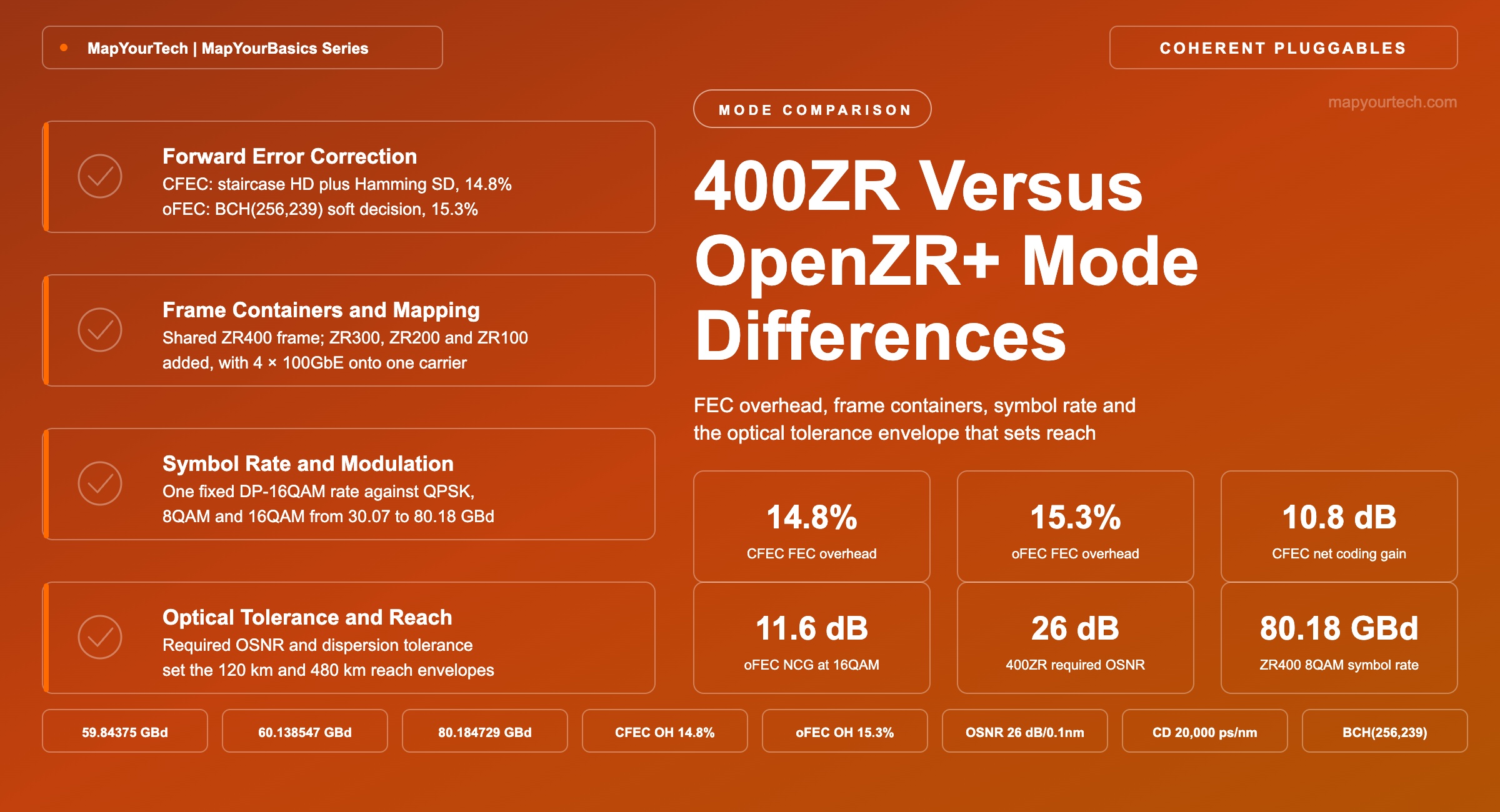
The FEC code is the largest functional difference between the two specifications, and the mode set, the symbol rate and the tolerance envelope all follow from it. CFEC is a concatenated scheme: an outer hard-decision staircase code at rate 0.937 feeding an inner Hamming(128,119) code, double-extended and soft-decision decoded, at rate 0.930, giving a total overhead of 14.8% (standard-specified, OIF-400ZR Implementation Agreement). It delivers a net coding gain (NCG) near 10.8 dB and corrects a pre-FEC bit error ratio (BER) around 1.22 × 10⁻² to a post-FEC floor below 1.0 × 10⁻¹⁵. CFEC was selected for DCI because it reaches that gain with modest decoder complexity, which keeps both silicon area and latency low.
OFEC is a block-convolutional soft-decision code. Each constituent component codeword is an extended Bose-Chaudhuri-Hocquenghem BCH(256,239) codeword carrying 17 parity bits, so the code rate is 111/128 = 0.867 and the overhead is 17/111 = 15.3% (standard-specified, OpenZR+ MSA, clause 7.1). With three soft-decision iterations the MSA states a net coding gain of 11.1 dB for DP-QPSK and 11.6 dB for DP-16QAM at a post-FEC BER of 10-15, with a pre-FEC BER threshold of 2.0 × 10⁻², and a combined encoder plus decoder latency below 3 µs. Against CFEC that is roughly 0.8 dB of extra coding gain at 16QAM, and a pre-FEC BER threshold about 1.6 times higher — the receiver stays in service on a noisier signal.
FEC Overhead From the Component Code
OH = p / (n − p) and R = (n − p) / n
Where:
- OH — FEC overhead, expressed as a fraction of the information bits (typical coherent range 7–30%)
- R — code rate, information bits per transmitted bit (typical range 0.77–0.94)
- n — bits per half-codeword position in the OFEC array, n = 128
- p — parity bits per constituent component codeword, p = 2N − k = 256 − 239 = 17
For OFEC: OH = 17 / 111 = 15.3% and R = 111 / 128 = 0.867. For CFEC the two concatenated stages multiply, 0.937 × 0.930 = 0.871, which inverts to 14.8% overhead. The half-percent difference in overhead buys roughly 0.8 dB of net coding gain at 16QAM, because OFEC decodes with soft information across iterations while the CFEC outer stage decodes hard.
Latency moves the other way. Iterative soft-decision decoding costs interleaver depth and decoder passes, so an OFEC link accumulates more fixed delay in the module than a CFEC link carrying the same client. The four code families in coherent service, their bounds and their decision types are set out in the FEC families reference. For links where the delay budget is contested — financial routes, tightly synchronised radio access transport — that difference belongs in the budget alongside fiber propagation delay, and the component split is treated in the MapYourTech analysis of latency in OTN and ZR/ZR+ coherent pluggables.
Interoperability constraint
FEC choice determines interoperability, not vendor branding. A ZR400-CFEC-16QAM transmitter and a ZR400-OFEC-16QAM receiver do not interwork, because the frame adaptation, coder block structure and symbol rate all differ. Modules that support both — and most 400G coherent pluggables shipping today do — select the mode through the Common Management Interface Specification (CMIS) application code, and both ends must be set to the same one.
5. Frame Containers and Client Mapping
Both specifications share the ZR400 frame. It is 10,280 bits wide by 256 rows, organised as forty 257-bit blocks per row, with the first twenty 257-bit blocks of the first row carrying alignment markers, pad and overhead, and the remaining 10,220 257-bit blocks carrying payload (standard-specified, OpenZR+ MSA, clause 3.2, cloned from the 400ZR Implementation Agreement). Client Ethernet is adapted to the frame by the generic mapping procedure (GMP) of ITU-T G.709 Annex D, operating across four consecutive frames with a stuffing granularity of 4 × 257 bits and justification control carried in the JC1–JC6 overhead bytes.
OpenZR+ adds three reduced-bandwidth containers built the same way: ZR300 at 192 rows and 7,665 payload blocks, ZR200 at 128 rows and 5,110 payload blocks, and ZR100 at 5,140 bits by 128 rows with 2,555 payload blocks. It also adds one overhead field the OIF frame does not carry, the Media Slot Identifier (MSI), which maps host ports to tributary slot instances and makes the multiplexing modes addressable. That single byte is what converts a transceiver into a muxponder function: one ZR400 frame can carry 1 × 400GBASE-R, 2 × 200GBASE-R or 4 × 100GBASE-R, each client independently GMP-mapped into its own tributary and its own overhead block. ZR300 carries 3 × 100GBASE-R; ZR200 carries 1 × 200GBASE-R or 2 × 100GBASE-R.
The operational consequence is direct. A router estate that has not yet moved to 400GbE ports can still fill a 400G wavelength, because four 100GbE clients ride one carrier with no external muxponder shelf. Neither specification carries Optical Transport Network (OTN) clients — both are Ethernet-only on the host side, and OTN transport over a comparable pluggable requires the Open ROADM interface set instead.
Takeaway: The frame is common ground; the container set is not. Multiplexing 4 × 100GbE onto one wavelength is an OpenZR+ capability that 400ZR does not offer at any revision.
6. Line Rate Expansion and Symbol Rate
Symbol rate is not chosen; it falls out of the frame arithmetic. The OpenZR+ specification publishes the full expansion chain from nominal server payload rate to line symbol rate, and each factor names a real overhead stage: padding to align the payload on 257-bit boundaries, the OFEC encoder ratio 4096/3552, the frame alignment word and training sequence, and the pilot symbol insertion at one symbol in thirty-two.
Symbol Rate From Frame Expansion Factors
Rs = fp,server × (512/511) × (37296/37265) × (4096/3552) × (899/896) × (32/31) / m
Where:
- Rs — line symbol rate in GBd (specified range 30.07–80.18 GBd across OpenZR+ modes)
- fp,server — nominal server payload bit rate, 401.703640510 Gb/s for ZR400
- 512/511 and 37296/37265 — alignment and pad insertion ratios
- 4096/3552 — OFEC encoder expansion, output block over input block
- 899/896 — frame alignment word and training sequence insertion
- 32/31 — pilot symbol insertion, one pilot every 32 symbols
- m — bits per symbol per polarization pair: 8 for DP-16QAM, 6 for DP-8QAM, 4 for DP-QPSK
All figures are standard-specified in the OpenZR+ MSA Technical Specification, clause 10.
Practical Example — symbol rate for the ZR400 16QAM and 8QAM modes
Start from fp,server = 401.703640510 Gb/s. Applying the five expansion factors in order gives a gross line rate of 481.108374 Gb/s, which is exactly the application bit rate the specification lists against media interface identifier 46h. Dividing by 8 bits per symbol for DP-16QAM gives 60.138546798 GBd. Dividing the same 481.108374 Gb/s by 6 bits per symbol for DP-8QAM gives 80.184729064 GBd — the ZR400-OFEC-8QAM mode. The 8QAM mode carries the same 400G payload at a lower constellation order, so the symbol rate rises by the ratio 8/6, and the required OSNR falls because each symbol carries fewer bits. That is the whole trade: a third more analog bandwidth for a lower OSNR requirement on the same payload.
400ZR sits at 59.843750000 GBd for the same 400G payload, slightly below the OpenZR+ 16QAM rate because CFEC's 14.8% overhead is marginally lighter than OFEC's 15.3%. A 400ZR channel and a 400ZR+ 16QAM channel therefore occupy nearly identical spectrum and both fit comfortably in a 75 GHz slot; the 80.18 GBd 8QAM mode does not, which is why the specification pairs it with a 100 GHz grid. Slot width follows the flexible-grid rules of ITU-T G.694.1, a point developed further in the MapYourTech treatment of alien wavelengths over third-party line systems.
7. Optical Tolerance and Reach Envelope
Required OSNR is where the FEC difference becomes a planning number. The 400ZR Implementation Agreement specifies 26 dB/0.1 nm back-to-back OSNR tolerance at end of life for the amplified application code. OpenZR+ specifies 24 dB for 400G, 21 dB for 300G, 16 dB for 200G and 12.5 dB for 100G (standard-specified, OpenZR+ MSA). Roughly 0.8 dB of the 2 dB gap between the two 16QAM figures is OFEC's higher net coding gain; the balance sits in the implementation margin each document allocates, so the two numbers are not a like-for-like measurement of the same receiver.
Chromatic dispersion tolerance separates the two even more sharply than OSNR. 400ZR specifies 2,400 ps/nm, which is enough for roughly 120 km of ITU-T G.652 fiber and no more. OpenZR+ specifies link chromatic dispersion up to 20,000 ps/nm at 400G, 40,000 ps/nm at 300G, 50,000 ps/nm at 200G and 100,000 ps/nm at 100G, with a 30,000 ps/nm figure for the 400G 8QAM mode on the 100 GHz grid. Instantaneous differential group delay (DGD) tolerance follows the same pattern, rising from the 400ZR figure to 50 ps at 400G and 83 ps at 100G in OpenZR+. The wider equalizer is a large part of why the OpenZR+ digital signal processor (DSP) draws more power.
| Parameter | OIF 400ZR | OpenZR+ |
|---|---|---|
| Line rates | 400G only | 100G, 200G, 300G, 400G |
| Modulation | DP-16QAM | DP-QPSK, DP-8QAM, DP-16QAM |
| FEC | CFEC, 14.8% overhead, NCG 10.8 dB | OFEC, 15.3% overhead, NCG 11.1–11.6 dB |
| Pre-FEC BER threshold | 1.22 × 10⁻² | 2.0 × 10⁻² |
| Required OSNR at 400G | 26 dB/0.1 nm | 24 dB/0.1 nm |
| Chromatic dispersion | 2,400 ps/nm | 20,000 ps/nm at 400G to 100,000 ps/nm at 100G |
| Channel spacing | 75 GHz grid, 3.125 GHz tuning | 75 GHz; 100 GHz for the 80 GBd 8QAM mode |
| Minimum Tx output power | −10 dBm | −10 dBm standard; 0 dBm in high-power designations |
| Client mapping | 1 × 400GBASE-R | Up to 4 × 100GBASE-R or 2 × 200GBASE-R |
| Unamplified application | Defined, 11 dB loss budget | Not defined; DWDM link parameters only |
| Add/drop structure | Colored | Colored and colorless |
Reach follows from those tolerances rather than being specified directly. For 400ZR the Implementation Agreement states the target explicitly: 120 km or less on an amplified point-to-point DWDM link. OpenZR+ states optical parameters instead of a distance, and the MSA's own white paper works a 400G example over 480 km built from six 80 km spans of G.652 fiber at 0.22 dB/km with erbium-doped fiber amplifiers (EDFAs) only and a 48-channel 100 GHz athermal arrayed waveguide grating add/drop structure. The MSA describes 400G regional interconnects beyond 1,000 km and 200G reaches beyond 2,500 km (MSA claim). Those longer figures generally assume the high transmit power modes, which is the subject of the MapYourTech reference on 0 dBm coherent transceivers, and they depend on the line system as much as on the module — open line system filter cascades and launch power settings decide whether a claimed reach is available on a given route.
Takeaway: The 2 dB OSNR advantage is measurable but modest. The order-of-magnitude dispersion tolerance and the option to drop to QPSK are what take an OpenZR+ module past the 120 km line.
8. Module Power and Thermal Class
Neither specification states a module power figure. Power is bounded by the form factor: the QSFP-DD MSA hardware specification defines power classes up to 14 W plus a class above 14 W, allows a maximum module power dissipation of at least 25 W, and rates each module power contact at 1.5 A (standard-specified, QSFP-DD MSA Hardware Specification). Within that envelope, the delivered figure is a vendor implementation result.
The practical separation between the two mode families is a few watts. A 400G coherent pluggable in QSFP-DD dissipates roughly 15 to 20 W, against an OIF 400ZR design target near 15 W, with shipping modules landing close to 19 W. Vendor datasheets for dual-mode 400ZR/OpenZR+ modules list typical consumption near 21 W and maximum near 22.5 W in 400GbE mode, rising by about 1 W in 4 × 100GbE mode where four independent GMP mappers and four tributary overhead processors run concurrently (vendor claim). Three mechanisms account for the increase: iterative soft-decision OFEC decoding runs more passes than the CFEC outer stage, the equalizer spans an order of magnitude more dispersion, and the high-power designations add an amplification stage inside the module.
That extra draw still compares well against the alternative. A 400G wavelength on a conventional transponder slot — coherent module plus host line card plus framing electronics — runs closer to 60 W for the same line capacity, which is the argument developed in the MapYourTech analysis of power per bit for router optics. The constraint that bites first is not the module but the host: a fully populated line card of high-power coherent modules can exceed the cage cooling design, and faceplate thermal capacity is why 800G modules in OSFP now sit at 25 to 30 W per port. The same host-density question drove the hardware shift covered in compact modular optical hardware.
9. Mode Selection Guidelines
400ZR is the lower-power choice wherever four conditions hold together: the route is a point-to-point amplified DWDM link at or below 120 km, the client is a single 400GbE port, delivered OSNR clears 26 dB with margin, and accumulated dispersion stays under 2,400 ps/nm. That envelope covers most metro DCI, and inside it 400ZR carries the lowest watts per bit and the widest supplier base. The unamplified application code with its 11 dB loss budget covers campus and short inter-building spans with no line system at all.
OpenZR+ becomes the required choice as soon as any one of four conditions appears: the route passes through reconfigurable optical add-drop multiplexers (ROADMs) and needs the extra coding gain and dispersion tolerance; the client mix includes 100GbE or 200GbE ports sharing a wavelength; delivered OSNR sits below the 400ZR requirement where a lower-order modulation format would recover the link; or the design calls for 0 dBm launch into a colored or colorless add/drop structure. The cost is a few watts per port and a mode-configuration step both ends must agree on.
Three commissioning steps carry most of the risk. The application code is set explicitly at both ends rather than left to defaults, because a module supporting both CFEC and OFEC will not link up across a mismatch. Delivered OSNR is measured against the specified requirement at the receiver reference point rather than at the transmitter, since the add/drop structure and the amplifier cascade both contribute; the measurement discipline is set out in the MapYourTech guide to coherent transponder test and measurement. And the provisioned slot width has to match the occupied bandwidth of the selected mode — the 80 GBd 8QAM mode needs a wider slot than the 60 GBd modes that share the same 400G payload, a distinction that also separates colored optics from grey optics in planning terms.
Design rule
Where a route sits close to the 400ZR OSNR or dispersion limit, specify the OpenZR+ module even if the initial service is 400G at 16QAM. The mode set gives an in-service fallback to 300G or 200G if the line system degrades or the span plan changes, and that option does not exist on a 400ZR module.
10. Summary
400ZR and OpenZR+ share the ZR400 frame and diverge at the FEC. CFEC at 14.8% overhead and 10.8 dB net coding gain supports one mode — DP-16QAM at 59.84 GBd, one 400GBASE-R client, 26 dB required OSNR, 2,400 ps/nm dispersion tolerance, 120 km amplified or an 11 dB unamplified budget. OFEC at 15.3% overhead and 11.1 to 11.6 dB net coding gain supports four line rates from 100G to 400G across DP-QPSK, DP-8QAM and DP-16QAM at 30.07, 60.14 or 80.18 GBd, with required OSNR from 24 dB down to 12.5 dB, dispersion tolerance from 20,000 to 100,000 ps/nm, and Ethernet multiplexing of up to four 100GbE clients onto one carrier. The flexibility costs a few watts per module and one more configuration decision per link.
The same architectural pattern repeats at the next generation: an OIF baseline for the single-span DCI case, and an MSA extension carrying a higher-gain code and a wider mode set beyond it. That pattern governs 800ZR and 800ZR+, and it shapes the 1600ZR-class pluggables now in specification.
References
- Optical Internetworking Forum, Implementation Agreement 400ZR (OIF-400ZR), Optical Internetworking Forum.
- OpenZR+ Multi-Source Agreement, Open ZR+ MSA Technical Specification, OpenZR+ MSA Group.
- OpenZR+ Multi-Source Agreement, OpenZR+: 400G Digital Coherent Optics for Multi-Haul, OpenZR+ MSA Group.
- ITU-T, Recommendation G.709/Y.1331 — Interfaces for the Optical Transport Network, International Telecommunication Union.
- ITU-T, Recommendation G.694.1 — Spectral Grids for WDM Applications: DWDM Frequency Grid, International Telecommunication Union.
- QSFP-DD MSA, QSFP-DD Hardware Specification for QSFP Double Density 8X Pluggable Transceiver, QSFP-DD MSA Group.
Sanjay Yadav, "Optical Network Communications: An Engineer's Perspective" — Bridge the Gap Between Theory and Practice in Optical Networking.
Related Articles on MapYourTech