
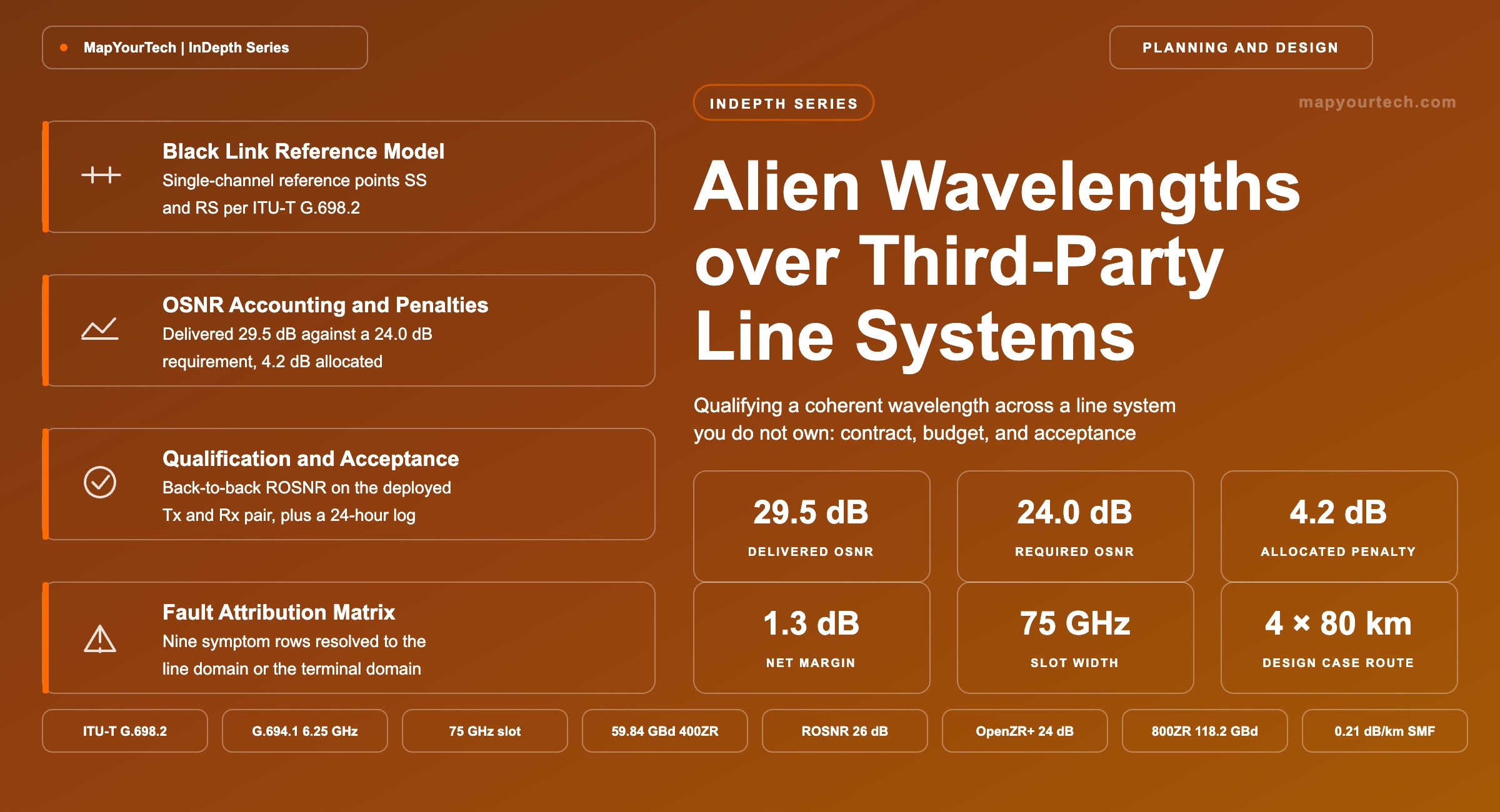
Alien Wavelengths over Third-Party Line Systems
Running a transponder's wavelength across amplifiers you do not own means qualifying it against that line, allocating penalties you cannot measure end to end, and owning the OSNR margin operationally.
What you can measure, you can improve.
What You Will Learn
- Define the alien wavelength boundary using the ITU-T G.698.2 black-link reference points SS and RS, and name which parameter each party owns at each point.
- Construct the eleven-parameter optical contract of Table 1, including launch power, slot width, delivered OSNR and maximum reflectance at the add and drop ports.
- Compute delivered OSNR from launch power, amplifier noise figure and span loss using the 58 dB reference constant at 1550 nm and 12.5 GHz.
- Quantify the 4.2 dB penalty allocation of Table 2 and close the worked 4 × 80 km margin calculation to 1.3 dB net.
- Convert symbol rate to occupied bandwidth and to the next 12.5 GHz flexible-grid slot per ITU-T G.694.1, and check 60.14 GBd against a 75 GHz slot.
- Select a qualification path from the Figure 3 procedure, including the back-to-back required-OSNR measurement on the actual transmitter and receiver pair.
- Anchor acceptance criteria to standard-specified values: 26 dB/0.1 nm for OIF 400ZR and 24 dB/0.1 nm for 400G OpenZR+.
- Apply the Table 3 fault matrix to isolate a degradation to the line domain or the terminal domain when neither party holds a segment monitor.
1. Introduction
An alien wavelength is a coherent carrier that leaves one operator's transponder, propagates through another operator's amplifiers, wavelength selective switches and fiber, and terminates in a receiver the line-system owner never sees. The optical layer carries no framing that either party can inspect, so the only shared observables are a launch power at the add port, a frequency slot, and whatever the line system's optical channel monitor reports at the drop. Everything else — modulation format, symbol rate, forward error correction gain, digital signal processing behaviour — sits on one side of the boundary while the physics that degrades it sits on the other.
The commercial pull is obvious. A carrier that already owns fiber and amplification can sell a wavelength instead of a managed service and keep the customer's transponder choice open. A hyperscale operator that has standardised on pluggable coherent optics can push those modules into leased regional and long-haul routes rather than buying a second transponder tier. A network operator consolidating after an acquisition can run inherited terminals across the surviving line system instead of replacing both. In each case the transponder becomes a black box to the line, and the line becomes a black box to the transponder.
The engineering cost of that arrangement is a measurement problem. In a single-vendor system the planning tool holds accurate models of every amplifier, every filter shape and every receiver, and it predicts end-of-life margin from first principles. Introduce a transponder the tool has no model for and the prediction degrades into a generic estimate padded with margin. Introduce a line system whose amplifier noise figures and filter shapes are commercially confidential and the estimate degrades further. Neither party can measure the whole path: the line system owner has no access to pre-forward-error-correction bit error rate, and the transponder owner has no access to per-span optical power profiles.
What replaces the missing model is a written optical contract and a qualification programme that validates it. ITU-T G.698.2 supplies the structural half of that contract by defining single-channel reference points on either side of an amplified multichannel link and specifying the parameters that must hold there (standard-specified, ITU-T G.698.2 edition of November 2018). Coherent interface agreements from the Optical Internetworking Forum and the OpenZR+ and Open ROADM multi-source agreements supply the transponder half by fixing symbol rate, forward error correction, slot occupancy and required optical signal-to-noise ratio for named application codes. The gap between the two — nonlinear interference, filter cascade narrowing, polarization dependent loss, control-loop error, transmitter and receiver pairing variance — is what an operator has to allocate, measure and own.
This article works through that gap in the order an engineer meets it: the reference model and where the boundary sits, the architecture and the parameters that cross it, the optical signal-to-noise ratio arithmetic with a complete worked margin calculation, the design decisions that set slot width and launch power, the qualification and acceptance procedure, the monitoring baseline, and the fault matrix that applies when a channel degrades and neither party holds a segment monitor. Readers who want the architectural context for open line systems first should read the treatment of multi-vendor coherent wavelengths over open line systems, and those who want the noise accounting from the ground up will find it in the companion material on in-house multivendor optical link planning.
Takeaway: An alien wavelength converts a modelling problem into a contractual and measurement problem. The parameters that used to be resolved inside one vendor's planning tool now have to be written down at two reference points and verified by test.
2. Alien Wavelength Definition and Reference Model
An alien wavelength is any optical channel whose transmitter and receiver are not under the control of the line system that carries it. The definition is relational rather than technical: the same coherent module is native on its own vendor's line system and alien on every other one. Nothing about the signal changes when it crosses that boundary; what changes is who holds the model that predicts its performance and who can act on the controls that protect it.
Three properties follow directly. First, alien wavelength support is a capability of the line system, not of the transponder — a line system either accepts a channel it cannot provision and cannot query, or it does not. Second, the boundary is optical rather than electrical, so the demarcation is a connector face and a set of optical parameters measured at that face. Third, because no protocol crosses the boundary, coordinated actions such as automatic laser shutdown and channel-level power adjustment have to be reconstructed from local monitoring rather than from signalling between the two domains.
Read the Full Analysis with Premium
The remaining 89% of this article — the design numbers, trade-offs and field guidance — is part of MapYourTech Premium, along with the full premium library, courses and professional tools.
You May Also Like

-
Free
-
September 4, 2026

-
Premium
-
September 4, 2026

-
Premium
-
September 4, 2026