
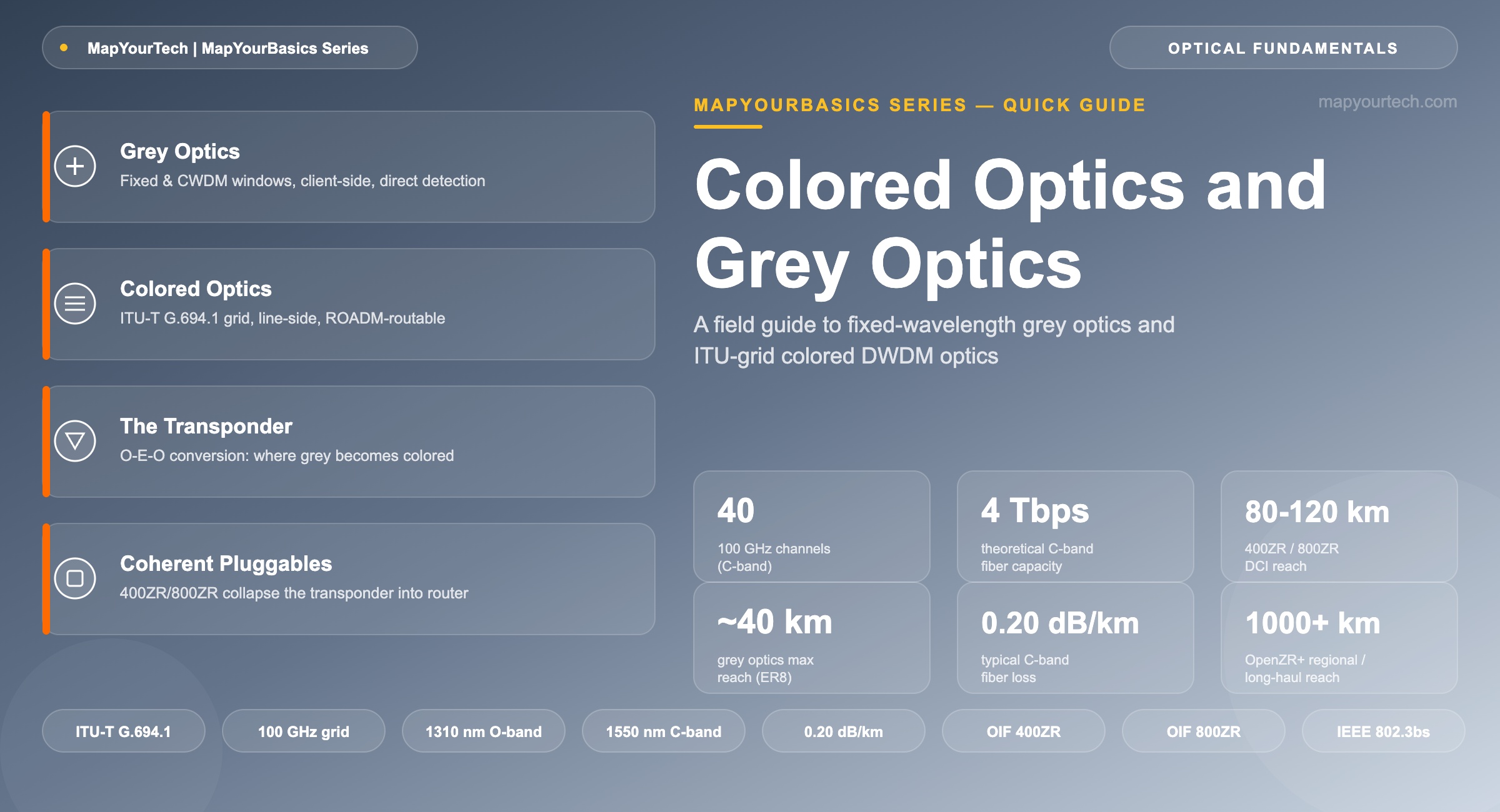
Colored Optics and Grey Optics: A Quick Guide
A practitioner's guide to the physical difference between grey (fixed-wavelength) and colored (ITU-T grid) optical transceivers, and where each belongs in a DWDM network.
1. Introduction
A grey optic and a colored optic can sit in the same faceplate cage and look identical from the outside — same QSFP28 body, same LC or MPO connector, same green activation LED. The difference is inside the laser. A grey optic transmits in a fixed wavelength window — 850 nm, 1310 nm, or occasionally 1550 nm — chosen for reach and cost, not for coexistence with other channels on the same fiber. A colored optic transmits at one specific frequency on the ITU-T G.694.1 Dense Wavelength Division Multiplexing (DWDM) grid, engineered to sit next to dozens of other channels on the same strand without interfering with them.
That single distinction decides where each optic can be deployed. Grey optics connect a router or switch to its nearest neighbor — another router, a patch panel, a transponder. Colored optics connect into a shared, amplified DWDM line system that multiplexes many wavelengths onto one fiber pair. This guide covers the physical basis for the grey/colored split, the wavelength grid that colored optics are built around, the transponder function that historically converted one into the other, and the current generation of coherent pluggables that increasingly do both jobs in a single QSFP-DD or OSFP module. It closes with practical guidance on when each type belongs in a network design.
2. Core Concepts
2.1 Grey Optics: Fixed Windows, Client-Side Reach
Grey optics operate in one of a small number of fixed wavelength windows: 850 nm (multimode), 1310 nm (O-band, the zero-dispersion window for G.652 single-mode fiber), or 1550 nm (C-band edge, used for extended-reach single-wavelength links). Some grey modules use more than one wavelength — the CWDM4 family behind 400GBASE-FR4 uses four wavelengths at 1271, 1291, 1311, and 1331 nm, spaced 20 nm apart under ITU-T G.694.2. Even with four wavelengths, a CWDM4 optic stays grey: it is not built to interleave with other channels through a shared amplified line system, and none of its wavelengths lands on the narrow ITU-T G.694.1 DWDM grid a ROADM expects.
Grey optics are direct-detection: a laser is switched (or PAM4-modulated) and a photodiode reads intensity, with no coherent receiver, no local oscillator, and no per-channel wavelength lock. That simplicity keeps cost and power low — a 400GBASE-DR4 module typically draws in the range of 8-12 W — but caps reach. IEEE 802.3bs-family grey optics span roughly 500 m (DR4, MPO-12, 1310 nm) to 2 km (FR4) to 10 km (LR4/LR8) to about 40 km (ER4/ER8), the point past which fiber loss outruns an uncooled, unamplified laser's power budget.
2.2 Colored Optics: ITU-Grid Wavelengths, Line-Side Reach
Colored optics are built around the ITU-T G.694.1 frequency grid, anchored at 193.10 THz (1552.52 nm) with a fixed spacing of 12.5, 25, 50, or 100 GHz, or a flexible grid with 6.25 GHz central-frequency granularity. Each channel gets its own slot — a 100 GHz-spaced C-band system fits up to 40 channels between roughly 1530 and 1565 nm; a 50 GHz grid doubles that to 80. A tunable laser inside the colored optic locks onto one of those slots, because a wavelength that drifts into a neighboring channel's slot degrades both signals. That wavelength-specificity is what lets a passive multiplexer combine dozens of colored channels onto one fiber pair, and what lets a Reconfigurable Optical Add-Drop Multiplexer (ROADM) route each channel independently through a mesh network without touching the others.
Not every colored optic is coherent. Older tunable DWDM SFP+ and XFP modules at 10 Gbps used direct detection on an ITU-grid wavelength — colored, but not coherent — and reached roughly 80 km with EDFA amplification. Above 100 Gbps, coherent detection becomes the practical default, because only a coherent receiver's digital signal processor (DSP) can undo the chromatic dispersion and polarization effects that accumulate at those baud rates over amplified distance. Colored and coherent are two separate, orthogonal properties of an optic — a distinction worth holding onto, since the terms are frequently used as if they meant the same thing.
2.3 Why "Grey" and "Colored"
The names come from how a DWDM system looks on a spectrum analyzer. A multiplexed, amplified DWDM line displays as a comb of discrete peaks — each channel occupying its own narrow slice of the C-band or L-band spectrum, conventionally drawn in a different color on planning diagrams and management screens. A client-side optic, by contrast, carries a single unstructured signal with no defined position in that comb; on the same diagrams it is typically rendered in grey, because it never appears on the wavelength plan. The terminology is a network-diagram convention, not a description of the light itself — both grey and colored optics emit visible or near-infrared light, and neither is literally grey or colored.
Takeaway: Grey describes a fixed or CWDM wavelength with no assigned position on a shared line system; colored describes a wavelength locked to an ITU-T G.694.1 grid slot so it can be multiplexed and routed with other channels. Coherent detection is a separate property that usually — but not universally — comes bundled with colored optics above 100 Gbps.
3. Technical Details
3.1 The Transponder: Where Grey Becomes Colored
A transponder is the device that historically separated grey and colored domains. On its client side, it terminates a grey optic — a QSFP28 100GbE port, for example — and performs optical-to-electrical (O/E) conversion. On its line side, it drives a colored optic tuned to an assigned ITU-T grid slot and performs the reverse electrical-to-optical (E/O) conversion, adding forward error correction (FEC) overhead in the process. A muxponder performs the same conversion for several lower-rate grey clients at once, time-division multiplexing them onto a single higher-rate colored wavelength — four 100GbE clients onto one 400G colored channel, for instance. The transponder or muxponder chassis is the reason legacy DWDM networks have three physical layers between two routers: the router itself, the transponder shelf, and the open line system that carries the colored wavelength. Removing that middle layer is the specific job of the coherent pluggable transceivers covered in Section 3.3.
3.2 Capacity Math: Why Colored Wins at Scale
A single grey optic delivers exactly one channel's bit rate, whatever that rate is. A colored line scales by wavelength count instead. Narrowing the grid to 50 GHz spacing and raising the per-channel rate to match current coherent colored pluggables pushes the same fiber toward multi-terabit aggregate capacity across 80 channels; adding the L-band alongside the C-band roughly doubles the available spectrum again. This is the structural reason DWDM networks exist at all: fiber is expensive to install and slow to add, so multiplying capacity per strand by stacking colored channels is cheaper than pulling new grey-only fiber for every increment of traffic.
C = total fiber capacity (Gbps or Tbps)
N = number of colored (ITU-T grid) wavelengths the grid and amplifier bandwidth support
B = bit rate carried per colored wavelength (Gbps)
Practical Example — C-Band Fiber Loaded with 100 Gbps Colored Channels: a 100 GHz-spaced C-band system (evidence class: standard-specified, ITU-T G.694.1) supports up to N = 40 channels. Loaded at B = 100 Gbps per channel, C = 40 × 100 Gbps = 4 Tbps aggregate — a theoretical maximum no single grey link, whatever its own rate, can approach on the same fiber pair.
3.3 Coherent Pluggables: Colored Optics in a Grey-Sized Footprint
The OIF 400ZR Implementation Agreement, completed in 2020, was the first specification to package a full coherent DWDM transceiver — tunable laser, coherent modulator, coherent receiver, and DSP — inside a QSFP-DD or OSFP module that plugs directly into a router or switch faceplate. A 400ZR module is a colored optic in every sense: it tunes to an assigned ITU-T grid slot, typically on 75 GHz spacing, and reaches roughly 80-120 km over an amplified point-to-point or lightly-ROADMed link, which covers most data center interconnect (DCI) routes. The OIF released the 800ZR Implementation Agreement in October 2024, doubling capacity with roughly 118 Gbaud DP-16QAM signaling over the same 80-120 km single-span DCI target (evidence class: standard-specified, OIF-800ZR-01.0). OpenROADM's ZR+ specifications extend the same pluggable form factor with probabilistic constellation shaping and flexible modulation — QPSK through 16QAM — reaching regional and long-haul distances beyond 1,000 km in favorable conditions.
This is Section 3.1's transponder function, absorbed into the router or switch line card: the grey client link and the separate transponder chassis both disappear, and the router speaks a colored, coherent wavelength directly onto the DWDM line system — an architecture generally referred to as IP over DWDM (IPoDWDM). Higher-power 0 dBm-class coherent modules extend this model into brownfield carrier ROADM networks that a lower-power DCI module could not traverse unamplified, and the same collapsed architecture is examined end to end in the MapYourTech IPoDWDM architecture walkthrough and the 800G ZR/ZR+ coherent optics guide.
Takeaway: The transponder's job — converting a grey client signal into a colored line wavelength — has not disappeared. In a coherent pluggable, it has moved from a separate chassis into the router or switch itself, which is why the industry increasingly talks about coherent optics rather than transponders as the unit of network design.
4. Practical Guidelines
Choosing between grey and colored optics is mostly a question of reach and topology, not raw preference. Use grey optics for any link that starts and ends inside the same facility, or between two adjacent sites with dark fiber and a short, unamplified span: server-to-switch, switch-to-router, router-to-transponder, or a direct DR4/FR4 building-to-building hop under a few kilometers. Grey optics are the cheaper, lower-power choice per port, and there is no reason to pay for wavelength tunability or coherent DSP on a link that never touches a shared DWDM line system.
Use colored optics whenever the signal needs to travel across a shared, amplified fiber alongside other channels, or through a ROADM that routes by wavelength. That includes nearly every metro, regional, and long-haul span, and increasingly includes DCI links that exceed a grey optic's unamplified reach. Within colored optics, match the pluggable class to the route: 400ZR/800ZR for amplified point-to-point DCI up to roughly 120 km, OpenZR+ variants for metro and regional routes with ROADM hops, and dedicated long-haul transponders — still the highest-performance DSPs available, as covered in the MapYourTech comparison of router-hosted versus embedded coherent optics — for ultra-long-haul and submarine routes beyond roughly 1,500 km, where a pluggable's power and thermal budget runs out.
Practical Example — DCI Link Design: two data center campuses sit 55 km apart on leased dark fiber. A grey 400GBASE-ER8 module can reach that distance unamplified, but only carries one 400G channel per fiber pair. A single 400ZR colored pluggable on the same fiber, amplified at each end, reaches the same 55 km and leaves room to add further colored channels — 800ZR, additional 400ZR wavelengths, or both — on the same strand as traffic grows. The grey option is cheaper for exactly one channel; the colored option is cheaper the moment a second channel is needed on the same fiber pair.
A practical rule of thumb for network designers: if the link needs to survive being demultiplexed at an intermediate ROADM node or coexist with other wavelengths on the same fiber, it needs a colored optic. If it terminates at the first piece of equipment it reaches, grey is enough.
Grey Optics vs. Colored Optics at a Glance
| Attribute | Grey Optics | Colored (DWDM) Optics |
|---|---|---|
| Wavelength assignment | Fixed window (850 / 1310 / 1550 nm) or CWDM (20 nm spacing, ITU-T G.694.2) | ITU-T G.694.1 grid slot (12.5-100 GHz fixed, or 6.25 GHz flex-grid) |
| Detection method | Direct detection (on-off keying or PAM4) | Direct detection (legacy, up to ~10 Gbps) or coherent (100 Gbps and above) |
| Typical form factors | SFP+, QSFP28, QSFP-DD (DR4 / FR4 / LR4 / LR8) | Tunable DWDM SFP+ / XFP; CFP2-DCO; QSFP-DD / OSFP (400ZR / 800ZR) |
| Typical reach | ~100 m (SR) to ~40 km (ER8), unamplified | ~80 km (direct-detect) to 1,000+ km (coherent, amplified / ROADM-routed) |
| Line-system compatible | No — point-to-point only | Yes — multiplexed, amplified, ROADM-routable |
| Typical network position | Client-side, intra-office, short DCI | Line-side, metro / regional / long-haul, shared DCI fiber |
| Relative cost and power per port | Lowest | Higher (tunable laser, thermal control, and DSP where coherent) |
5. Summary
Grey and colored describe where an optic's wavelength sits, not how fast it runs or how it is built. A grey optic uses a fixed or CWDM wavelength window chosen for cost and short reach, with no defined position on a shared line system. A colored optic tunes to a specific ITU-T G.694.1 grid slot so it can be multiplexed, amplified, and routed alongside dozens of other channels on the same fiber. The transponder historically converted one into the other; coherent pluggables such as 400ZR and 800ZR increasingly do both jobs inside a single module, colored and coherent by design, seated directly in a router faceplate. For a network design, the deciding question is simple: does this link ever touch a shared, amplified, wavelength-routed fiber? If yes, it needs a colored optic. If no, grey is enough — and cheaper.
References
- ITU-T G.694.1 — Spectral grids for WDM applications: DWDM frequency grid, ITU-T Study Group 15.
- ITU-T G.694.2 — Spectral grids for WDM applications: CWDM wavelength grid, ITU-T Study Group 15.
- IEEE 802.3bs — Media Access Control Parameters, Physical Layers, and Management Parameters for 200 Gb/s and 400 Gb/s Operation, IEEE Standards Association.
- OIF-800ZR-01.0 — Implementation Agreement for 800ZR Coherent Interfaces, Optical Internetworking Forum.
Sanjay Yadav, "Optical Network Communications: An Engineer's Perspective" – Bridge the Gap Between Theory and Practice in Optical Networking.
Related Articles on MapYourTech






