

ITU-T G.694.1 DWDM Channel Grid: Fixed Grid, Flexible Grid, and Frequency Calculation
Understanding the frequency grid that defines modern DWDM channel placement — from conventional 100/50 GHz fixed grids to the flexi-grid extension enabling 400G, 800G, and beyond
1. Introduction
Dense Wavelength Division Multiplexing (DWDM) is the cornerstone technology of modern optical transport networks. By transmitting dozens or hundreds of distinct wavelengths simultaneously through a single optical fiber, DWDM enables aggregate capacities that reach tens of terabits per second on a single fiber pair. The orderly placement of these wavelengths across the optical spectrum is not left to chance — it is governed by the ITU-T Recommendation G.694.1, one of the most widely referenced standards in optical networking.
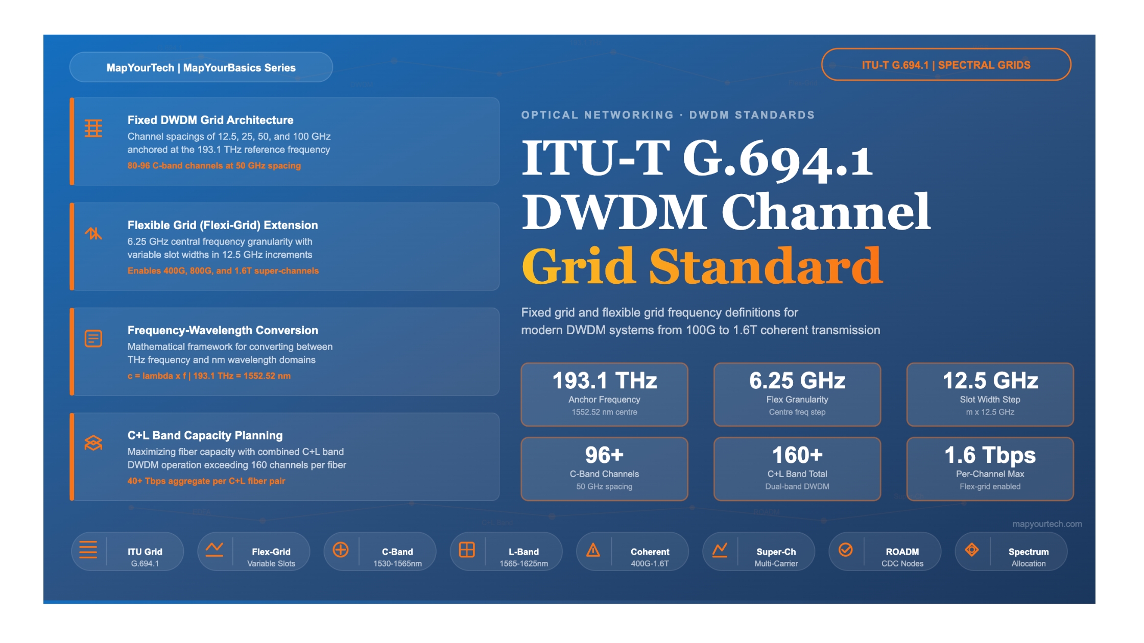
ITU-T G.694.1, titled "Spectral grids for WDM applications: DWDM frequency grid," defines the frequency grid that all DWDM equipment manufacturers, system integrators, and network operators rely on for interoperability. The standard was first published in June 2002, received a major revision in February 2012 that introduced the flexible (flexi-grid) extension, and was most recently updated in October 2020. The anchor point of the entire grid is 193.1 THz, which corresponds to approximately 1552.52 nm in the C-band.
This article provides a thorough treatment of the G.694.1 standard. It covers the fixed-grid definitions at 12.5, 25, 50, and 100 GHz channel spacings; the mathematical relationship between optical frequency and wavelength; the flexible grid concept with its 6.25 GHz central-frequency granularity and 12.5 GHz slot-width granularity; and the practical significance of these grids for deploying high-capacity coherent systems at 400G, 800G, and beyond.
ITU-T G.694.1 defines the spectral grids for DWDM applications. The standard supports fixed channel spacings of 12.5, 25, 50, and 100 GHz (and integer multiples of 100 GHz), as well as a flexible grid. All frequencies are specified relative to the anchor frequency of 193.1 THz. The standard does not specify wavelengths as primary parameters — wavelength values provided in the standard are approximations derived from the frequency definitions.
2. Historical Evolution of the DWDM Grid
The standardisation of DWDM channel placement evolved in step with the rapid growth of optical transport capacity from the mid-1990s onward. Understanding this evolution provides important context for appreciating why the grid is structured the way it is today.
2.1 From G.692 to G.694.1
The original specification for multi-channel optical interfaces was ITU-T G.692, which defined transmission parameters for optical systems using optical amplifiers and wavelength-division multiplexing. As channel counts grew and tighter spacings became necessary, the ITU-T separated the spectral grid definition into its own recommendation: G.694.1 for DWDM and G.694.2 for Coarse WDM (CWDM). G.694.1 was first published in June 2002, defining the fixed grid with spacings from 12.5 GHz up to 100 GHz and wider, all anchored at 193.1 THz.
2.2 The 2012 Revision: Arrival of the Flexible Grid
By the early 2010s, coherent optical transmission was transforming the industry. Systems carrying 40G and 100G per wavelength used modulation formats and symbol rates that did not always fit neatly into the rigid 50 GHz or 100 GHz slots. Furthermore, the drive toward super-channels — where multiple optical carriers are grouped together to form a single logical high-capacity channel — demanded the ability to allocate variable-width spectrum blocks. Edition 2.0 of G.694.1, published in February 2012, introduced the flexible DWDM grid (often called the flexi-grid). This extension defines frequency slots with a central-frequency granularity of 6.25 GHz and a slot-width granularity of 12.5 GHz, enabling network operators and equipment to allocate exactly the amount of spectrum each signal requires.
2.3 The 2020 Update
The October 2020 revision of G.694.1 refined definitions and clarified the interaction between the fixed and flexible grids. It remains the current in-force version of the standard as of 2025. The revision confirmed that the flexible grid parameters are designed so that any configuration expressible on a fixed grid can also be described using suitable choices of slots on the flexible grid, ensuring backward compatibility.
3. Fundamental Principles: Frequency, Wavelength, and the Anchor
3.1 The Relationship Between Frequency and Wavelength
Optical signals are electromagnetic waves characterised by their frequency (f) and wavelength (λ). In a vacuum, these are related by the speed of light (c):
c = λ × f

Where:
  c  = speed of light in vacuum = 299,792,458 m/s (approximately 3 × 10⁸ m/s)
  λ = wavelength in meters
  f  = frequency in Hertz
This relationship can be rearranged to convert between frequency and wavelength:
f = c / λ     — Frequency from wavelength
λ = c / f     — Wavelength from frequency

For the ITU anchor frequency:
  f = 193.1 THz = 193.1 × 10¹² Hz
  λ = 299,792,458 / (193.1 × 10¹²) = 1552.524 nm (approximately 1552.52 nm)
An important nuance is that the relationship between frequency and wavelength is inversely proportional and not linear. A constant frequency spacing does not correspond to a constant wavelength spacing. For small frequency differences (Δf) around a central frequency (f0), the approximate equivalent wavelength spacing is:
Δλ ≈ −(λ2 / c) × Δf

Where:
  Δλ = wavelength spacing (m)
  λ  = centre wavelength (m)
  c   = speed of light (m/s)
  Δf  = frequency spacing (Hz)

The negative sign indicates that an increase in frequency corresponds to a decrease in wavelength.At the C-band centre around 1550 nm (193.4 THz):
Δλ = (1550 × 10-9)2 / (3 × 108) × 100 × 109
Δλ = (2.4025 × 10⁻¹²) / (3 × 108) × 1011
Δλ ≈ 0.8008 × 10⁻⁹ m = approximately 0.8 nm
This is why 100 GHz channel spacing is often referred to as "0.8 nm spacing" in practical engineering. Similarly, 50 GHz corresponds to approximately 0.4 nm at C-band wavelengths.
3.2 Why Frequency, Not Wavelength, Is the Primary Grid Parameter
G.694.1 explicitly states that the specifications applied to DWDM applications are defined with respect to nominal central frequencies, not wavelengths. The wavelength values listed in the standard are approximations only. There are good engineering reasons for this choice. Frequency is an intrinsic property of the optical field that does not change as light passes through different media (fiber core, air gaps in connectors, optical coatings). Wavelength, by contrast, changes with the refractive index of the medium. Defining the grid in frequency ensures unambiguous interoperability regardless of the optical components in the signal path.
3.3 The Anchor Point: 193.1 THz
The entire DWDM grid is anchored at 193.1 THz (approximately 1552.52 nm). This anchor sits near the centre of the C-band, which is the most widely used band for DWDM due to its coincidence with the lowest-loss window of standard single-mode fiber (approximately 0.19–0.22 dB/km at 1550 nm) and the gain band of Erbium-Doped Fiber Amplifiers (EDFAs). All fixed-grid channel frequencies are defined as offsets from this anchor, and the flexi-grid central frequencies are likewise referenced to it.
Interactive DWDM Calculator
4. The Fixed DWDM Grid
4.1 Grid Definition and Formula
The fixed grid defines nominal central frequencies using a simple formula referenced to the 193.1 THz anchor:
fn = 193.1 + n × Δf   (THz)

Where:
  n   = a positive or negative integer (including zero)
  Δf = channel spacing: 12.5, 25, 50, or 100 GHz
       (or integer multiples of 100 GHz)
The standard supports four fixed spacings: 100 GHz (the original "coarse" DWDM grid), 50 GHz (the most widely deployed spacing today), 25 GHz, and 12.5 GHz. These spacings evolved historically by successive factors-of-two subdivision of the initial 100 GHz grid. Uneven channel spacings using any combination of these fixed grids are also permitted by the standard.
4.2 Channel Spacing Details
| Channel Spacing | Approximate Δλ at 1550 nm | C-Band Channels (approx.) | Typical Application |
|---|---|---|---|
| 100 GHz | 0.8 nm | ~44 channels | Metro DWDM, cost-sensitive deployments, 10G/40G per-channel rates |
| 50 GHz | 0.4 nm | ~88 channels | Most widely deployed grid; 10G, 40G, 100G coherent; backbone and long-haul |
| 25 GHz | 0.2 nm | ~176 channels | Ultra-dense systems, research environments |
| 12.5 GHz | 0.1 nm | ~352 channels | Theoretical maximum density; basis for flexi-grid slot width granularity |
Table 1: Fixed Grid Spacing Options Defined in ITU-T G.694.1
4.3 Example: 100 GHz Grid in the C-Band
The 100 GHz grid places channels at 191.0, 191.1, 191.2, ... , 196.0 THz across the combined L-band and C-band region. Within the conventional C-band (approximately 191.0 to 196.0 THz), a typical 100 GHz deployment supports around 44 channels. With the 50 GHz offset grid, the interleaved channels (e.g., 191.05, 191.15 THz) double the channel count to approximately 88 channels, which is the most common configuration in deployed DWDM networks today.
Problem: Find the frequency and wavelength for ITU channel number 34 on the 100 GHz grid (using the convention where channel n = 34 means an offset of 34 × 100 GHz from 191.0 THz).
Step 1: The channel frequencies on the 100 GHz grid relative to 193.1 THz anchor use n values such that f = 193.1 + n × 0.1 THz. For channel 34, the frequency is typically 193.4 THz (this corresponds to n = 3 from the 193.1 anchor).
Step 2: Convert to wavelength: λ = c / f = 299,792,458 / (193.4 × 10¹²) = 1550.12 nm
This wavelength falls very close to the centre of the C-band, which is the most commonly used wavelength region for DWDM systems.
4.4 The Number of Channels in a Band
The number of DWDM channels that can fit within a given wavelength band depends on the channel spacing and the usable bandwidth of the optical amplifiers and multiplexer/demultiplexer devices. The general formula is:
N = (λ2 − λ1) / Δλ + 1

Or equivalently in frequency:
N = (fupper − flower) / Δf + 1

Where:
  λ1, λ2     = extreme wavelengths of the band
  Δλ           = channel spacing in nm
  fupper, flower = boundary frequencies of the band
  Δf           = channel spacing in GHz

Example: C-band from 1535 nm to 1565 nm at 50 GHz (~0.4 nm):
N = (1565 − 1535) / 0.4 + 1 = 75 + 1 = 76 channels
In practice, deployed C-band 50 GHz systems typically support 80–96 channels
depending on the exact amplifier bandwidth and filter characteristics.
Figure 1: Fixed DWDM Grid — Comparison of Channel Density at 100 GHz vs 50 GHz Spacing in C-Band
5. The Flexible DWDM Grid (Flexi-Grid)
5.1 Motivation for Flexibility
The fixed grid works well when all channels use the same data rate and modulation format with similar spectral widths. However, modern coherent optical systems operate at baud rates ranging from 32 GBaud to 140+ GBaud, with modulation formats from BPSK to 64QAM and beyond. A 32 GBaud DP-QPSK signal carrying 100G requires roughly 37.5 GHz of spectrum, while a 64 GBaud DP-16QAM signal carrying 400G needs approximately 75 GHz. An 800G super-channel built from dual carriers may need 150 GHz. Forcing all of these into uniform 50 GHz or 100 GHz slots leads either to wasted spectrum (when slots are wider than needed) or to signal impairment from filter narrowing effects (when slots are too tight). The flexible grid solves this problem by allowing variable-width frequency slots that can be tailored to each signal's actual bandwidth requirement.
5.2 Flexi-Grid Definition
The flexible DWDM grid defines frequency slots using two parameters:
Nominal Central Frequency:
fcenter = 193.1 + n × 0.00625 THz   (6.25 GHz granularity)

Slot Width:
Slot Width = m × 12.5 GHz

Where:
  n = a positive or negative integer (defines the centre frequency)
  m = a positive integer (defines the slot width)

Constraint: No two frequency slots may overlap.

Common slot widths:
  m = 2 → 25 GHz    (narrow; low-baud-rate signals)
  m = 3 → 37.5 GHz  (100G DP-QPSK @ 32 GBaud)
  m = 4 → 50 GHz    (compatible with fixed 50 GHz grid)
  m = 6 → 75 GHz    (400G single-carrier @ 64 GBaud)
  m = 8 → 100 GHz   (compatible with fixed 100 GHz grid)
  m = 12 → 150 GHz  (800G super-channels)
5.3 Why 6.25 GHz for Central Frequency Granularity?
The choice of 6.25 GHz granularity for the central frequency is deliberate. Since the smallest fixed-grid spacing is 12.5 GHz, the slot-width granularity must also be 12.5 GHz to maintain compatibility. When a slot with a width that is an even multiple of 12.5 GHz is placed adjacent to a slot with an odd-multiple width, the central-frequency granularity must be 6.25 GHz to allow the two slots to be packed together without any gap or overlap. This design ensures that the flexi-grid can represent any configuration achievable with the fixed grid, while also enabling arbitrary mixed-width slot arrangements.
The flexi-grid is designed so that any fixed-grid configuration can be expressed using the flexible grid. For example, the standard 50 GHz fixed grid can be represented as a series of frequency slots, each with m = 4 (slot width = 50 GHz), centred on the corresponding fixed-grid frequencies. This ensures that legacy 50 GHz systems and new flexi-grid systems can coexist on the same fiber infrastructure.
5.4 Fixed Grid vs. Flexible Grid: Side-by-Side Comparison
Fixed Grid
All channels occupy identical, predetermined bandwidth slots (e.g., 50 GHz or 100 GHz). Simple to plan and manage. Every channel gets the same spectrum allocation regardless of actual signal bandwidth. Best suited for uniform-rate systems (e.g., all channels at 10G or 100G with the same modulation).
Advantage: Simplicity, proven interoperability, lower-cost mux/demux and ROADM hardware.
Limitation: Spectrum is wasted when signal bandwidth is less than slot width; cannot efficiently support mixed-rate traffic or wide super-channels.
Flexible Grid
Each channel can occupy a custom-width slot (in multiples of 12.5 GHz), placed at 6.25 GHz-granularity positions. Ideal for mixed-rate environments and super-channel formation. Enables packing 100G, 400G, and 800G signals onto the same fiber with optimized spectral efficiency.
Advantage: Maximized spectral efficiency, support for super-channels, future-proof for evolving baud rates and modulation formats.
Limitation: Requires flex-grid-capable ROADMs and network management; higher hardware and software complexity.
| Parameter | Fixed Grid | Flexible Grid |
|---|---|---|
| Central frequency granularity | Equal to spacing (e.g., 50 GHz) | 6.25 GHz |
| Slot width | Fixed (12.5 / 25 / 50 / 100 GHz) | m × 12.5 GHz (variable) |
| Spectral efficiency | Moderate — unused spectrum within each slot is wasted | High — slot width matches signal bandwidth |
| Super-channel support | Limited — super-channels must span multiple fixed slots | Native — single wide slot allocated for super-channel |
| ROADM requirement | Standard fixed-grid WSS | Flex-grid WSS with configurable bandwidth |
| Network management | Simpler channel planning | Requires spectrum allocation algorithms and fragmentation management |
| Backward compatibility | Baseline | Fully compatible — fixed grid is a subset of flex grid |
Table 2: Fixed Grid vs. Flexible Grid Comparison
5.5 Visualizing Flexible Grid Slot Allocation
6. Super-Channels and High-Capacity Coherent Transmission
6.1 What Is a Super-Channel?
A super-channel is a high-capacity optical channel formed by aggregating multiple closely-spaced optical carriers (sub-carriers) into a single logical entity. The sub-carriers are generated by one transmitter or a tightly coordinated group of transmitters, and they are received together as a single channel. Super-channels enable data rates beyond what a single optical carrier can efficiently achieve, such as 800G, 1.2T, and beyond.
The flexible grid is essential for super-channel deployment. Instead of fitting each sub-carrier into its own fixed-width slot with guard bands between them, a flexi-grid system allocates a single wide slot for the entire super-channel. For example, an 800G super-channel using two 64 GBaud DP-16QAM sub-carriers can be allocated a single 150 GHz slot (m = 12), with the sub-carriers packed tightly together inside that slot with minimal or no guard band between them. This approach significantly improves spectral efficiency compared to assigning two separate 75 GHz fixed-grid slots with a guard band in between.
6.2 Spectrum Allocation for Modern Coherent Systems
| Data Rate | Typical Modulation | Approx. Baud Rate | Signal Bandwidth | Recommended Flex-Grid Slot (m value) |
|---|---|---|---|---|
| 100G | DP-QPSK | 32 GBaud | ~35 GHz | 37.5 GHz (m=3) or 50 GHz (m=4) |
| 200G | DP-16QAM | 32 GBaud | ~35 GHz | 37.5 GHz (m=3) or 50 GHz (m=4) |
| 400G | DP-16QAM | 64 GBaud | ~69 GHz | 75 GHz (m=6) |
| 400G (long-haul) | DP-QPSK | 64 GBaud | ~69 GHz | 75 GHz (m=6) |
| 800G (single carrier) | DP-64QAM / PCS | ~130 GBaud | ~140 GHz | 150 GHz (m=12) |
| 800G (dual carrier) | DP-16QAM × 2 | 64 GBaud each | ~140 GHz total | 150 GHz (m=12) |
| 1.2T–1.6T | DP-64QAM / PCS | 130–200 GBaud | 140–220 GHz | 150–225 GHz (m=12–18) |
Table 3: Typical Flex-Grid Slot Allocations for Modern Coherent Data Rates
6.3 The Role of Baud Rate and Roll-Off Factor
The actual occupied bandwidth of a coherent signal depends on the symbol (baud) rate and the pulse-shaping roll-off factor. The relationship is:
BWsignal = Rs × (1 + α)

Where:
  Rs    = symbol rate (baud rate) in GBaud
  α     = roll-off factor (typically 0.05 to 0.2 for modern coherent systems)
  BWsignal = occupied signal bandwidth in GHz

Example: 64 GBaud signal with α = 0.1:
BWsignal = 64 × (1 + 0.1) = 70.4 GHz
This fits within a 75 GHz flexi-grid slot (m=6).

Example: 130 GBaud signal with α = 0.1:
BWsignal = 130 × (1 + 0.1) = 143 GHz
This requires a 150 GHz flexi-grid slot (m=12).
7. C-Band and L-Band: Capacity and Channel Planning
7.1 Optical Bands Used for DWDM
While the G.694.1 grid is defined over a broad frequency range, practical DWDM systems primarily operate in two bands: the C-band (Conventional band, approximately 1530–1565 nm, or roughly 191.6–195.9 THz on the 100 GHz grid) and the L-band (Long band, approximately 1565–1625 nm, or roughly 184.5–191.6 THz). The C-band is preferred because of its coincidence with the lowest fiber attenuation (approximately 0.19–0.22 dB/km) and the gain bandwidth of standard EDFAs. As C-band capacity becomes exhausted, network operators add L-band capacity using L-band EDFAs or Raman amplification.
| Band | Wavelength Range | Frequency Range | Fiber Loss (dB/km) | Typical Channel Count (50 GHz) | Amplifier Technology |
|---|---|---|---|---|---|
| C-Band | 1530–1565 nm | 191.6–195.9 THz | 0.19–0.22 | 80–96 | C-band EDFA |
| L-Band | 1565–1625 nm | 184.5–191.6 THz | 0.20–0.24 | 80–96 | L-band EDFA, Raman |
| C+L Combined | 1530–1625 nm | 184.5–195.9 THz | 0.19–0.24 | 160+ | C+L EDFA, Raman hybrid |
Table 4: C-Band and L-Band Characteristics for DWDM
7.2 C+L Band: Doubling Fiber Capacity
C+L band DWDM systems have become a standard approach for maximizing the capacity of existing fiber infrastructure. By using both bands simultaneously, a single fiber can support well over 160 channels at 50 GHz spacing. With flexible-grid allocation and modern coherent transponders operating at 400G or 800G per channel, a single C+L fiber pair can carry aggregate capacities exceeding 40 Tbps. Recent industry demonstrations have pushed beyond even these numbers. At OFC 2025, researchers demonstrated over 1 petabit per second of aggregate capacity using advanced multi-core fiber and C+L band amplification, and individual vendors have shown 25.6 Tbps line capacities on single standard fiber.
8. Practical Applications and Deployment Scenarios
8.1 Metro Networks
In metropolitan networks, the fixed 50 GHz grid remains the most common configuration. Metro rings and mesh networks typically carry 100G or 400G per channel over distances of a few hundred kilometres. The 50 GHz grid supports 80–96 channels in the C-band, providing ample capacity for most metro applications. Flex-grid ROADMs are increasingly deployed in metro networks to support the coexistence of 100G and 400G services on the same infrastructure, with each service type allocated the appropriate slot width.
8.2 Long-Haul and Subsea Networks
Long-haul terrestrial and submarine networks are among the most demanding applications of the G.694.1 grid. These networks typically operate with tighter spectral management and often deploy C+L band configurations to maximize per-fiber capacity. Subsea cables, in particular, use flex-grid allocation to pack the maximum number of channels into the available amplifier bandwidth. Modern subsea systems operate at 400G to 1.2T per wavelength, with flex-grid slots of 75 to 150 GHz, depending on the modulation format and target reach.
8.3 Data Center Interconnects (DCI)
The DCI market has driven rapid adoption of both coherent DWDM and flex-grid technology. The OIF 400ZR and 400ZR+ specifications define coherent pluggable modules operating on the DWDM grid. 400ZR modules are designed for 75 GHz channel spacing (compatible with the flex-grid m=6 slot width), while 800ZR and 800ZR+ modules, which are entering deployment, use wider slot allocations. These pluggable coherent modules bring DWDM capabilities directly into IP routers and switches, enabling disaggregated network architectures that are becoming the dominant deployment model for hyperscale cloud providers.
8.4 Network Upgrades: Mixed-Rate Migration
One of the most practical benefits of the flexible grid is enabling smooth network upgrades. An operator can start with a 50 GHz fixed grid carrying 100G channels, then gradually introduce 400G channels in 75 GHz flex-grid slots and 800G super-channels in 150 GHz slots — all on the same fiber and through the same ROADM nodes. The flex-grid ROADM dynamically adjusts the spectral allocation as services are added, modified, or removed, without requiring a complete network redesign.
9. Channel Planning and Spectrum Management Challenges
9.1 Spectrum Fragmentation
A significant challenge with flexible-grid networks is spectrum fragmentation. As channels are added and removed over time, the available spectrum can become fragmented into small, non-contiguous blocks that are individually too narrow to accommodate new wide-bandwidth services. This is analogous to disk fragmentation in computing. Spectrum defragmentation techniques, including hitless wavelength shifting and make-before-break provisioning, are used to consolidate available spectrum and maintain efficient utilisation.
9.2 Filter Narrowing Effects
When a DWDM signal passes through multiple cascaded ROADMs and wavelength-selective switches, the effective passband becomes progressively narrower due to the multiplicative effect of the individual filter responses. This filter narrowing or "filter concatenation penalty" can degrade signal quality, particularly for signals that occupy most of their allocated slot width. Flex-grid systems mitigate this by allowing slightly wider slot allocations where needed to accommodate the expected number of ROADM passthrough nodes in the path.
9.3 Guard Bands
Even with flex-grid allocation, a small guard band is typically maintained between adjacent channels to account for laser frequency drift, filter edge steepness, and manufacturing tolerances. In practice, the guard band is often 3–6 GHz per side, which is why a 64 GBaud signal (occupying ~70 GHz with roll-off) fits well within a 75 GHz slot — the remaining 5 GHz provides a sufficient guard band.
10. ITU-T G.694.1 Grid Reference: C-Band 100 GHz Channels
The following table provides a subset of the most commonly referenced C-band channels on the 100 GHz grid. Remember that the standard defines frequencies as the primary parameter; wavelengths shown are approximations.
| # | Frequency (THz) | Wavelength (nm, approx.) | # | Frequency (THz) | Wavelength (nm, approx.) |
|---|---|---|---|---|---|
| 1 | 191.00 | 1569.59 | 26 | 193.50 | 1549.32 |
| 2 | 191.10 | 1568.77 | 27 | 193.60 | 1548.51 |
| 3 | 191.20 | 1567.95 | 28 | 193.70 | 1547.72 |
| 4 | 191.30 | 1567.13 | 29 | 193.80 | 1546.92 |
| 5 | 191.40 | 1566.31 | 30 | 193.90 | 1546.12 |
| 6 | 191.50 | 1565.49 | 31 | 194.00 | 1545.32 |
| 7 | 191.60 | 1564.67 | 32 | 194.10 | 1544.53 |
| 8 | 191.70 | 1563.86 | 33 | 194.20 | 1543.73 |
| 9 | 191.80 | 1563.04 | 34 | 194.30 | 1542.93 |
| 10 | 191.90 | 1562.23 | 35 | 194.40 | 1542.14 |
| 11 | 192.00 | 1561.41 | 36 | 194.50 | 1541.34 |
| 12 | 192.10 | 1560.60 | 37 | 194.60 | 1540.55 |
| 13 | 192.20 | 1559.79 | 38 | 194.70 | 1539.76 |
| 14 | 192.30 | 1558.98 | 39 | 194.80 | 1538.97 |
| 15 | 192.40 | 1558.17 | 40 | 194.90 | 1538.18 |
| 16 | 192.50 | 1557.36 | 41 | 195.00 | 1537.39 |
| 17 | 192.60 | 1556.55 | 42 | 195.10 | 1536.60 |
| 18 | 192.70 | 1555.75 | 43 | 195.20 | 1535.82 |
| 19 | 192.80 | 1554.94 | 44 | 195.30 | 1535.03 |
| 20 | 192.90 | 1554.13 | 45 | 195.40 | 1534.25 |
| 21 | 193.00 | 1553.33 | 46 | 195.50 | 1533.46 |
| 22 | 193.10 | 1552.52 | 47 | 195.60 | 1532.68 |
| 23 | 193.20 | 1551.72 | 48 | 195.70 | 1531.89 |
| 24 | 193.30 | 1550.92 | 49 | 195.80 | 1531.11 |
| 25 | 193.40 | 1550.12 | 50 | 195.90 | 1530.33 |
Table 5: ITU-T G.694.1 C-Band 100 GHz Grid — Selected Channels (Anchor: 193.1 THz / 1552.52 nm)
Figure 3: Spectral Efficiency Comparison — Fixed Grid vs. Flexible Grid for Different Channel Data Rates
11. Future Trends and Evolution
11.1 Beyond 800G: 1.6T and Multi-Terabit Channels
As coherent DSP technology advances to 3nm and below, baud rates are climbing beyond 130 GBaud toward 200 GBaud. Single-carrier 1.6T transmission has been demonstrated using 200 GBaud DP-64QAM modulation with probabilistic constellation shaping (PCS). These ultra-wide signals require flex-grid slots of 200 GHz or more (m = 16+), reinforcing the importance of flex-grid infrastructure in greenfield network deployments. At OFC 2025, multiple vendors showcased 800G multivendor interoperability as a mature, production-ready technology, while 1.6T demonstrations moved from proof-of-concept to early sampling. IEEE 802.3dj is defining the 1.6 Terabit Ethernet standard with 200G per electrical lane.
11.2 Extended Bandwidth: S-Band and Beyond
Research is actively exploring the use of additional wavelength bands beyond C+L to further increase fiber capacity. The S-band (1460–1530 nm) is the next candidate, and in 2025 NTT demonstrated the use of an ultra-long-wavelength "X band" (around 1700 nm) to extend the total usable optical bandwidth to 27 THz — approximately 6.7 times greater than the C-band alone. As these broader bands are commercialized, the G.694.1 grid (which already supports frequencies across the S, C, and L bands) will serve as the foundation for channel planning, with the flexi-grid extension providing the flexibility to accommodate diverse signal widths across these extended bands.
11.3 Spectrum-as-a-Service and Software-Defined Networking
The programmability of flex-grid ROADMs and coherent transponders enables a new operational model where spectrum can be dynamically allocated, traded, and managed as a software-defined resource. Operators can offer "spectrum-as-a-service" on shared fiber infrastructure, with flexi-grid slots provisioned on demand via SDN controllers. This model is particularly attractive for multi-tenant dark fiber and open-line-system deployments, where different customers may operate different data rates and modulation formats on the same physical fiber.
12. Conclusion
ITU-T G.694.1 is the foundational standard that governs DWDM channel placement across the global optical networking industry. Its fixed grid, anchored at 193.1 THz with spacings of 12.5, 25, 50, and 100 GHz, has served the industry reliably through multiple generations of optical transport technology. The flexible grid extension, with its 6.25 GHz central-frequency granularity and 12.5 GHz slot-width granularity, provides the spectral agility needed for modern coherent systems operating at 400G, 800G, and beyond.
Understanding this standard is essential for any optical network engineer involved in system design, channel planning, ROADM configuration, or capacity planning. The ability to convert between frequency and wavelength, to calculate channel counts for a given band and spacing, and to determine the appropriate flex-grid slot width for a given coherent signal are fundamental skills in the profession.
As the industry moves toward 1.6T and multi-terabit coherent channels, extended C+L+S band operation, and software-defined spectrum management, the G.694.1 framework — particularly its flexible grid — will continue to be the reference standard that enables interoperability and efficient spectrum use across diverse vendor ecosystems.
1. ITU-T G.694.1 defines the DWDM frequency grid anchored at 193.1 THz (approximately 1552.52 nm), with fixed spacings of 12.5, 25, 50, and 100 GHz.
2. The flexible grid (introduced in 2012) uses 6.25 GHz central-frequency granularity and 12.5 GHz slot-width granularity to enable variable-bandwidth channel allocation.
3. Frequency, not wavelength, is the primary grid parameter — wavelengths are approximations only.
4. Super-channels for 800G+ data rates rely on flexi-grid allocation to optimize spectral efficiency.
5. The standard supports backward compatibility: any fixed-grid configuration can be expressed using the flexible grid.
Glossary
- Anchor Frequency
- The reference frequency (193.1 THz) from which all G.694.1 grid channels are calculated.
- Baud Rate (Symbol Rate)
- The number of symbols transmitted per second, measured in GBaud. Determines the occupied signal bandwidth.
- C-Band
- The Conventional band of the optical spectrum, approximately 1530–1565 nm, the primary operating region for DWDM systems.
- CDC-ROADM
- Colorless, Directionless, Contentionless Reconfigurable Optical Add-Drop Multiplexer — the modern ROADM architecture supporting flex-grid operation.
- DWDM
- Dense Wavelength Division Multiplexing — the technology of transmitting multiple wavelengths simultaneously on a single fiber with narrow channel spacing.
- EDFA
- Erbium-Doped Fiber Amplifier — the standard optical amplifier for the C-band and L-band.
- Flexi-Grid
- The flexible portion of the G.694.1 standard, allowing variable-width frequency slots in multiples of 12.5 GHz.
- Frequency Slot
- In the flexi-grid, a contiguous block of spectrum defined by a central frequency and a slot width.
- Guard Band
- A small spectral gap between adjacent channels to prevent inter-channel interference.
- L-Band
- The Long band of the optical spectrum, approximately 1565–1625 nm, used as a capacity extension to the C-band.
- PCS
- Probabilistic Constellation Shaping — a technique to optimise the distribution of QAM constellation points for improved SNR sensitivity and spectral efficiency.
- Roll-Off Factor (α)
- A parameter of the pulse-shaping filter that determines how quickly the signal spectrum tapers off at its edges. Smaller values give tighter spectra.
- Spectral Efficiency
- The data throughput achieved per unit of optical spectrum, measured in bits per second per Hertz (b/s/Hz).
- Super-Channel
- A high-capacity optical channel formed by aggregating multiple sub-carriers into a single logical channel within a flexi-grid slot.
- WSS
- Wavelength Selective Switch — the core switching element in modern ROADMs that can route individual wavelengths or flex-grid slots to different output ports.
References
- ITU-T Recommendation G.694.1 — Spectral grids for WDM applications: DWDM frequency grid.
- ITU-T Recommendation G.694.2 — Spectral grids for WDM applications: CWDM wavelength grid.
- ITU-T Recommendation G.671 — Transmission characteristics of optical components and subsystems.
- ITU-T Recommendation G.709 — Interfaces for the optical transport network.
- IEEE 802.3df — Standard for 800 Gigabit Ethernet.
- OIF Flexgrid Label Format — Optical Internetworking Forum, Implementation Agreement for Flex-Grid Label Format.
- Sanjay Yadav, "Optical Network Communications: An Engineer's Perspective" — Bridge the Gap Between Theory and Practice in Optical Networking.
Developed by MapYourTech Team
For educational purposes in Optical Networking Communications Technologies
Note: This guide is based on industry standards, best practices, and real-world implementation experiences. Specific implementations may vary based on equipment vendors, network topology, and regulatory requirements. Always consult with qualified network engineers and follow vendor documentation for actual deployments.
Feedback Welcome: If you have any suggestions, corrections, or improvements to propose, please feel free to write to us at [email protected]
Related Articles on MapYourTech


Continue Reading This Article
Sign in with a free account to unlock the full article and access the complete MapYourTech knowledge base.


