
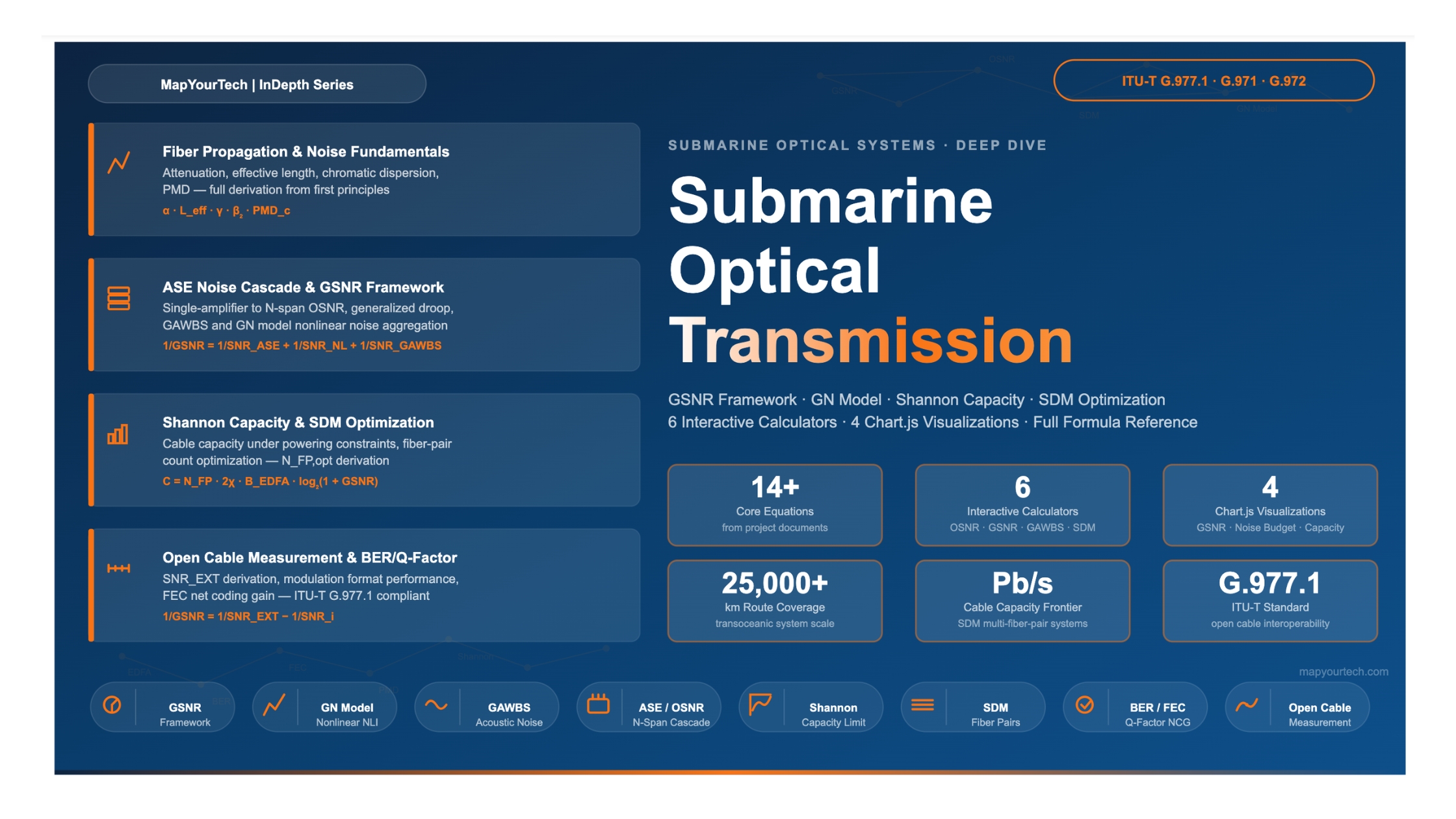

Ultralong-Haul Transmission in Submarine Optical Systems
A research-grade technical reference covering noise modeling, nonlinear physics, GSNR framework, and capacity design — with fully interactive formula calculators for design engineers.
Introduction
Submarine optical cable systems form the invisible backbone of global communications, carrying the vast majority of all international data traffic across oceans. The engineering challenge at their core — transmitting hundreds of terabits per second across transoceanic distances of 6,000 to 20,000 km using repeaters powered over a single high-voltage conductor — has no parallel in terrestrial networking. Every design decision carries irreversible financial and physical consequences, since deployed cable systems operate on the ocean floor for 25 years or more, far beyond the reach of ordinary maintenance.
The discipline of submarine optical transmission design is fundamentally an optimization problem. Engineers must simultaneously balance optical signal-to-noise ratio (OSNR), fiber nonlinear effects, cable powering limits, dispersion management, and spectral efficiency — all under the constraint that repeaters cannot be accessed after deployment. This article provides a rigorous technical treatment of the physical models that govern system performance, the analytical frameworks used to predict and optimize capacity, and the transition from single-fiber optimization toward space division multiplexing (SDM) as the architecture of the current decade.
The treatment covers the entire signal impairment hierarchy: amplified spontaneous emission (ASE) noise from cascaded optical amplifiers, fiber Kerr nonlinearities modeled through the Gaussian Noise (GN) model, and the recently characterized guided acoustic-wave Brillouin scattering (GAWBS) effect. These three independent but interacting noise sources define the Generalized Signal-to-Noise Ratio (GSNR), which is the central figure of merit in modern open submarine cable characterization, standardized under ITU-T G.977.1.
Scope of This Article
This article addresses repeatered long-haul submarine systems operating in the C-band and C+L-band. Unrepeatered and direct-detection systems are outside the scope. All formula derivations reference established models from ITU-T recommendations and peer-reviewed optical communications literature. Every interactive calculator uses these exact formulas, allowing engineers to explore design trade-offs directly within the article.
System Architecture and Building Blocks
A repeatered submarine cable system consists of a small number of fundamental elements whose interaction governs all performance outcomes. Understanding each element — and precisely how it contributes to noise — is the necessary foundation before any formula can be applied meaningfully.
2.1 The Amplified Span
The fundamental building unit is an amplified span: a length of transmission fiber terminated at each end by an erbium-doped fiber amplifier (EDFA). Each repeater in a modern submarine cable houses multiple EDFAs — one per fiber pair direction — that compensate exactly for the span loss accumulated over the preceding fiber section. Span lengths in submarine systems typically range from 50 to 100 km, with the repeater spacing set at manufacture and fixed for the cable lifetime.
EDFAs amplify the signal through stimulated emission in the erbium-doped fiber, but they also generate amplified spontaneous emission (ASE) noise, which accumulates irreversibly with each repeater traversal. The noise figure (NF) of each EDFA — typically 4 to 6 dB in modern submarine repeaters — quantifies how efficiently signal power is added relative to noise power. A lower noise figure directly translates to a higher end-to-end OSNR for a given cable length and span configuration.
2.2 Fiber Types and Their Role
The transmission fiber used in submarine cables directly affects both the linear (ASE-dominated) and nonlinear noise budgets. Two key parameters govern system performance:
Effective area (Aeff): A larger effective area reduces the optical power density within the fiber core, proportionally reducing all Kerr nonlinear effects. Premium submarine fibers achieve effective areas of 125–150 µm², compared to 80–110 µm² for standard single-mode fiber. The nonlinear noise power scales approximately as 1/Aeff², so a fiber with 150 µm² effective area generates roughly 4× less nonlinear interference power than a fiber with 80 µm².
Read the Full Analysis with Premium
The remaining 88% of this article — the design numbers, trade-offs and field guidance — is part of MapYourTech Premium, along with the full premium library, courses and professional tools.


