

Generic selectors
Exact matches only
Search in title
Search in content
Post Type Selectors
Articles
lp_course
lp_lesson
Back
HomeAutomationIn-Service Submarine Line Monitoring with COTDR and OSC
In-Service Submarine Line Monitoring with COTDR and OSC

In-Service Submarine Line Monitoring with COTDR and OSC

Last Updated: April 2, 2026
12 min read
99
In-Service Submarine Line Monitoring with COTDR and OSC
Submarine Systems

In-Service Submarine Line Monitoring with COTDR and OSC

How coherent optical time-domain reflectometry, integrated into the optical supervisory channel, maintains continuous health surveillance of in-service transoceanic cables without disrupting live traffic

Summary

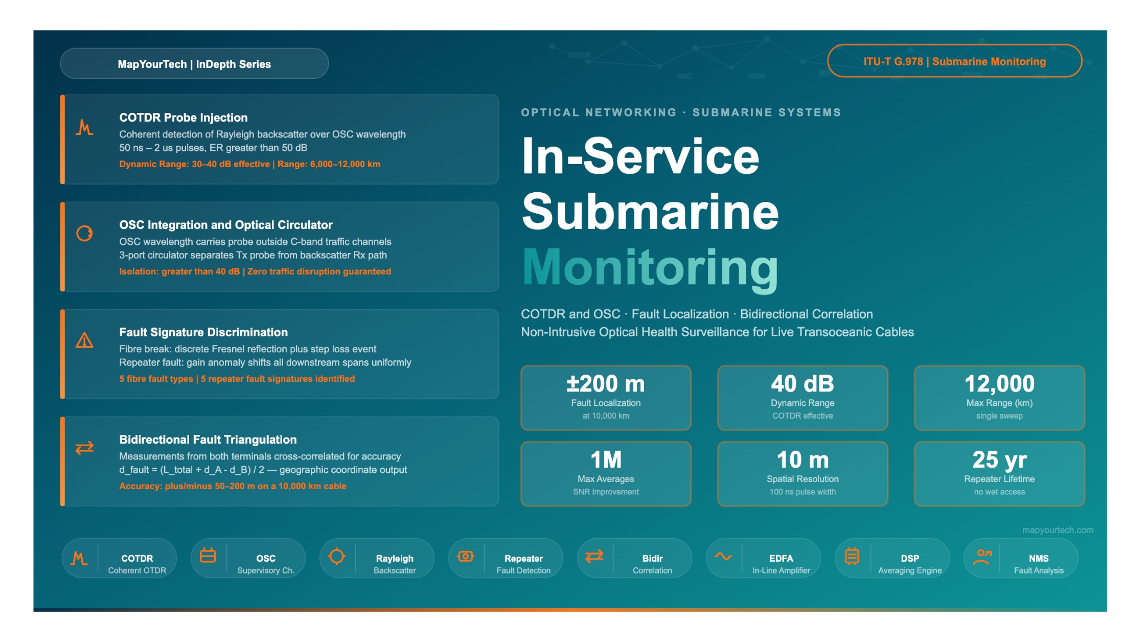
Transoceanic submarine cable systems represent one of the most demanding environments in telecommunications engineering. A single cable may span more than 12,000 km, pass through ocean depths exceeding 8,000 m, and carry hundreds of terabits of live traffic at any moment. Locating and characterizing a fault on such a system with sub-kilometre accuracy — while keeping all traffic channels intact — requires purpose-built monitoring architecture.

Coherent Optical Time-Domain Reflectometry (COTDR), delivered over the Optical Supervisory Channel (OSC), solves this problem. By injecting carefully crafted probe pulses outside the traffic band and using coherent detection to recover the returning Rayleigh backscatter and discrete reflections, COTDR achieves spatial resolution on the order of tens of metres across distances that exceed 10,000 km. This article examines the operating principles, system architecture, fault signature interpretation, bidirectional correlation, and practical accuracy achievable in modern submarine deployments.

Key performance figures addressed include: pulse widths and repetition rates, dynamic range targets above 30 dB, achievable dead zones at repeater sites, typical localization accuracy of ±50 m to ±200 m, and the correlation algorithms used to resolve a fault's true physical location from measurements taken at both cable termination stations.

1. Introduction and Background

Submarine cable networks carry more than 95% of all international internet traffic. The cables themselves are passive optical transmission media — glass fibers enclosed within a carefully engineered cable structure that provides mechanical strength, electrical isolation, and corrosion resistance. At intervals of approximately 45 to 80 km along the cable, submerged repeater units house optical amplifiers that restore signal power without converting the optical signal to electricity for data processing. These repeaters are designed for operational lifetimes exceeding 25 years and cannot be accessed for maintenance without a costly cable ship operation.

This combination of factors — extreme length, inaccessible amplifier sites, and the commercial consequences of traffic interruption — creates a unique requirement for optical health surveillance. Network operators need to know the condition of every fibre span and every repeater at all times. When a fault occurs, they need to determine whether it is a fibre problem (caused by cable movement, external aggression, or material degradation) or a repeater problem (caused by pump laser degradation or other internal amplifier failure), and they need to locate it precisely enough to dispatch a cable repair ship to the correct coordinate.

1.1 The Role of the Optical Supervisory Channel

The Optical Supervisory Channel (OSC) is a management wavelength that runs alongside the traffic-carrying wavelengths on a submarine cable but sits outside the traffic band. In C-band submarine systems, traffic channels occupy the 1530–1565 nm range, while the OSC typically operates at 1510 nm or below, or alternatively above 1625 nm in the O-band region around 1310 nm for some designs. Because the OSC wavelength is outside the erbium gain window of the in-line amplifiers, it is handled differently at each repeater — extracted, processed, regenerated, and reinserted — giving it hop-by-hop visibility into the network.

COTDR exploits the OSC path. The shore-based monitoring equipment injects COTDR probe pulses onto the OSC wavelength (or a dedicated monitoring wavelength carried over the same fibre as the OSC), and the returning backscatter is detected and processed at the terminal station. Because this happens on a wavelength separated from the traffic, live data channels experience no interruption.

1.2 Why Conventional OTDR Cannot Solve the Problem

A standard direct-detection OTDR — the instrument used for short-haul terrestrial fibre testing — cannot reach across a 10,000 km submarine cable. Rayleigh backscatter from a pulse injected at one terminal arrives back at that terminal after traveling 20,000 km (out and back), having traversed roughly 100 to 200 optical amplifiers each of which introduces amplified spontaneous emission (ASE) noise. The signal-to-noise ratio of the returned backscatter becomes negligible using conventional direct-detection receivers at these distances. Coherent detection, which mixes the returning signal with a stable local oscillator laser, provides an improvement in receiver sensitivity of 15 to 20 dB compared with direct detection, which is what makes transoceanic OTDR measurement feasible.

Figure 1: Submarine COTDR System Architecture — Shore-to-Shore View Ocean Floor (Seabed) TERMINAL STATION A COTDR Engine OSC Tx/Rx + Coherent RX Traffic Tx/Rx (C-band) Fault Analysis / NMS PFE (Power Feed Equip) TERMINAL STATION B COTDR Engine OSC Tx/Rx + Coherent RX Traffic Tx/Rx (C-band) Fault Analysis / NMS PFE (Power Feed Equip) REP 1 REP 2 FAULT REP 4 REP 5 COTDR Probe Pulse (OSC wavelength) Rayleigh Backscatter + Discrete Reflection COTDR Probe (reverse direction) COTDR Operating Concept Probe pulses (50 ns – 1 µs wide) are injected on the OSC. Returning Rayleigh backscatter is coherently detected. Fault position = (v x t) / 2, where v is the group velocity (~2×10⁴ km/s) and t is round-trip time. Bidirectional Correlation Benefit Measuring from both ends gives two distance estimates (d₁ from A, d₂ from B). True location is confirmed when d₁ + d₂ ≈ total cable length. Accuracy typically ±50 m to ±200 m at 10,000 km. Fault Type Discrimination Fibre break: strong discrete reflection + step loss Repeater fault: gain anomaly at known repeater position Partial damage: elevated loss + change in backscatter slope Bend/stress: localized attenuation spike, no reflection

Figure 1: Submarine COTDR system architecture showing probe injection from both terminal stations, repeater chain, and fault discrimination at a cable section midpoint.

2. Historical Evolution of Submarine Cable Monitoring

Early submarine telegraph cables in the nineteenth century used electrical resistance measurements from shore to estimate the position of a break. The same principle carried forward into the first generation of coaxial submarine telephone cables — a DC resistance bridge technique that gave fault location accuracy of approximately ±1% of the cable length, which on a 5,000 km cable translates to an uncertainty of ±50 km. That accuracy was adequate when the only diagnostic action was dispatching a cable ship to grapple for and raise the cable, because ship positioning over the cable was the limiting uncertainty.

The transition to all-optical transmission systems in the early 1990s, driven by the deployment of erbium-doped fibre amplifiers (EDFAs) in submarine repeaters, removed the electrical test access points that had existed in the coaxial era. Every amplified span is now a purely optical path, and the repeater electronics are sealed, powered through the sea earth return from shore, and inaccessible. The monitoring challenge became one of optical interrogation.

2.1 Direct-Detection OTDR Attempts

The first optical monitoring systems adapted standard OTDR technology. Probe pulses at 1625 nm — outside the amplifier gain band — were injected into the cable, and the returned backscatter was detected using avalanche photodiodes (APDs). These systems worked adequately on cable sections up to roughly 300 km, and they could supervise the first few repeater spans from shore. However, the dynamic range achievable with direct detection topped out around 35 to 40 dB, insufficient to cover a full ocean crossing of 6,000 to 12,000 km where accumulated fibre attenuation alone exceeds 1,000 dB before amplifier compensation is considered.

Averaging improved sensitivity but at the cost of measurement time. A direct-detection system collecting 10,000 averages to extend dynamic range by 20 dB required measurement periods of hours for each sweep, during which a slowly developing fault might not be captured. The temporal resolution of the monitoring was therefore poor.

2.2 Coherent Detection as the Enabling Technology

Coherent detection — mixing the returning signal with a narrow-linewidth local oscillator laser before photodetection — transforms the OTDR measurement problem. The coherent receiver responds to the electric field amplitude of the backscattered light rather than its intensity, and the phase-sensitive detection provides a sensitivity improvement of 15 to 20 dB over direct detection at the same optical bandwidth. This additional dynamic range, when combined with averaging over thousands of acquisitions, is what enables COTDR measurements to reach beyond 10,000 km.

Modern COTDR systems deployed on submarine cables are typically rated for measurement ranges of 6,000 to 12,000 km with dynamic ranges of 30 to 40 dB. These figures position COTDR as the de facto standard for in-service submarine cable monitoring.

1990s Direct Detection

~35 dB

Maximum dynamic range, limited to ~300 km monitoring reach

Modern COTDR

30–40 dB

Dynamic range over 10,000+ km; coherent detection is the key enabler

Localization Accuracy

±50–200 m

Achievable on a 10,000 km cable with bidirectional correlation

Premium Article — Free 20% Preview

Read the Full Analysis with Premium

The remaining 80% of this article — the design numbers, trade-offs and field guidance — is part of MapYourTech Premium, along with the full premium library, courses and professional tools.


Instant access · Cancel anytime · 48-hour trial available
Sanjay Yadav

Optical Communications & Network Automation Expert | Author of 3 Books for Optical Engineers | Founder, MapYourTech

Optical networking engineer with nearly two decades of experience across DWDM, OTN, coherent optics, submarine systems, and cloud infrastructure. Founder of MapYourTech.

Follow on LinkedIn

You May Also Like

52 min read 13 0 Like The Submarine Cable Stack: Open Cables, GSNR, SDM and Power Skip to main content...
  • Free
  • July 10, 2026
32 min read 10 0 Like Coherent DSP Architecture: From ADC Samples to Client Bits MAPYOURTECH | COHERENT OPTICS DEEP...
  • Free
  • July 10, 2026
42 min read 14 0 Like Building an Optical NOC Dashboard with OpenConfig Telemetry Skip to main content MapYourTech |...
  • Free
  • July 10, 2026

Course Title

Course description and key highlights

Course Content

Course Details
