
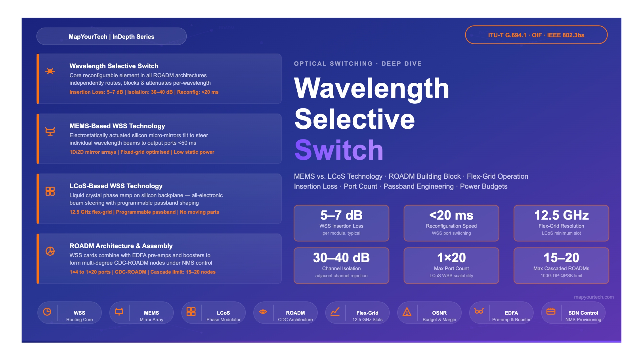

Wavelength Selective Switch Technology:
MEMS, LCoS, and the ROADM Building Block
A comprehensive engineering reference covering how MEMS-based and LCoS-based WSS technologies achieve per-wavelength routing, how they compare across insertion loss, port count, resolution, and reconfiguration speed, and how WSS cards assemble into full-degree ROADM nodes that power flexible optical transport networks.
- 1. Introduction
- 2. Historical Evolution
- 3. Fundamental Principles of WSS
- 4. MEMS-Based WSS Technology
- 5. LCoS-Based WSS Technology
- 6. Technology Comparison
- 7. ROADM Architecture & WSS Assembly
- 8. Performance & Optical Budgets
- 9. Practical Applications & Deployment
- 10. Challenges & Solutions
- 11. Future Trends
- 12. Conclusion
Introduction
The optical transport network has undergone a fundamental transformation over the past two decades. Where early Dense Wavelength Division Multiplexing (DWDM) systems relied on static point-to-point wavelength assignment, modern networks demand the ability to route, block, attenuate, and reassign individual wavelengths in real time—without touching the fiber physically and without converting optical signals to electrical form at every intermediate node.
The component that makes this agility possible is the Wavelength Selective Switch, universally abbreviated WSS. A WSS is a programmable optical device that accepts multiple wavelengths on one or more input ports and independently steers each wavelength to one of several output ports. It can simultaneously route one wavelength to the east, block another, attenuate a third to equalize channel power, and pass all remaining channels through to the line. This per-wavelength programmability, delivered in a single passive-optical subsystem, is what elevates a passive optical add-drop multiplexer into a Reconfigurable Optical Add-Drop Multiplexer (ROADM).
Two dominant physical mechanisms have emerged to implement a WSS: Micro-Electro-Mechanical Systems (MEMS), which tilt microscopic mirrors fabricated from silicon, and Liquid Crystal on Silicon (LCoS), which modulates the phase of reflected light through electrically controlled liquid crystal layers on a silicon backplane. Each technology offers a distinct trade-off profile across insertion loss, port count, frequency resolution, polarization sensitivity, and cost.
This reference covers the physics, architecture, and engineering parameters of both MEMS and LCoS WSS technologies; compares their performance numerically; explains how multiple WSS modules combine to form a multi-degree ROADM node; and addresses practical deployment considerations including optical power budgets, G-OSNR impact, and flex-grid operation.
Understanding WSS technology is central to designing DWDM networks that carry 100G, 400G, and 800G coherent channels over metro, regional, long-haul, and submarine infrastructure. As channel rates grow, the constraints imposed by WSS characteristics—passband width, group delay ripple, insertion loss, and port count—become increasingly important to link budgets and system margins.
Historical Evolution of Wavelength Routing Technology
2.1 Fixed Add-Drop Multiplexers
The first generation of optical add-drop nodes used fixed optical add-drop multiplexers (OADMs) based on Fiber Bragg Gratings (FBGs) or Thin-Film Filters (TFFs). These devices could extract a specific wavelength from a composite WDM signal for local delivery and inject a new signal at the same wavelength. While economical, fixed OADMs locked each wavelength to a fixed physical port at installation time. Changing a traffic assignment required a field visit and manual re-cabling—an operationally expensive and slow process incompatible with dynamic network management.
2.2 First-Generation ROADMs: Broadcast-and-Select
Early ROADMs used a broadcast-and-select (B&S) architecture: a power splitter broadcast all wavelengths to every output port, and a bank of optical switches or variable optical attenuators (VOAs) selected which wavelengths passed to each direction. While remotely reconfigurable, B&S nodes suffered from the fundamental limitation that splitting power N ways incurs a 10 log N dB splitting loss even before considering device loss. With four or eight output directions, this loss budget became prohibitive without additional amplification at every node.
2.3 Introduction of WSS-Based ROADMs
The introduction of WSS-based ROADMs marked a decisive architectural shift. Rather than splitting all wavelengths and then blocking the unwanted ones, a WSS selectively routes only those wavelengths that need to reach each output port. Wavelengths not destined for a port are simply not steered there—they are either directed to another port or blocked. This approach avoids the large splitting loss of B&S architectures and enables loss-efficient multi-degree node construction. WSS-based nodes became commercially viable in the mid-2000s and rapidly became the standard technology for all-optical networking.
Read the Full Analysis with Premium
The remaining 89% of this article — the design numbers, trade-offs and field guidance — is part of MapYourTech Premium, along with the full premium library, courses and professional tools.


