
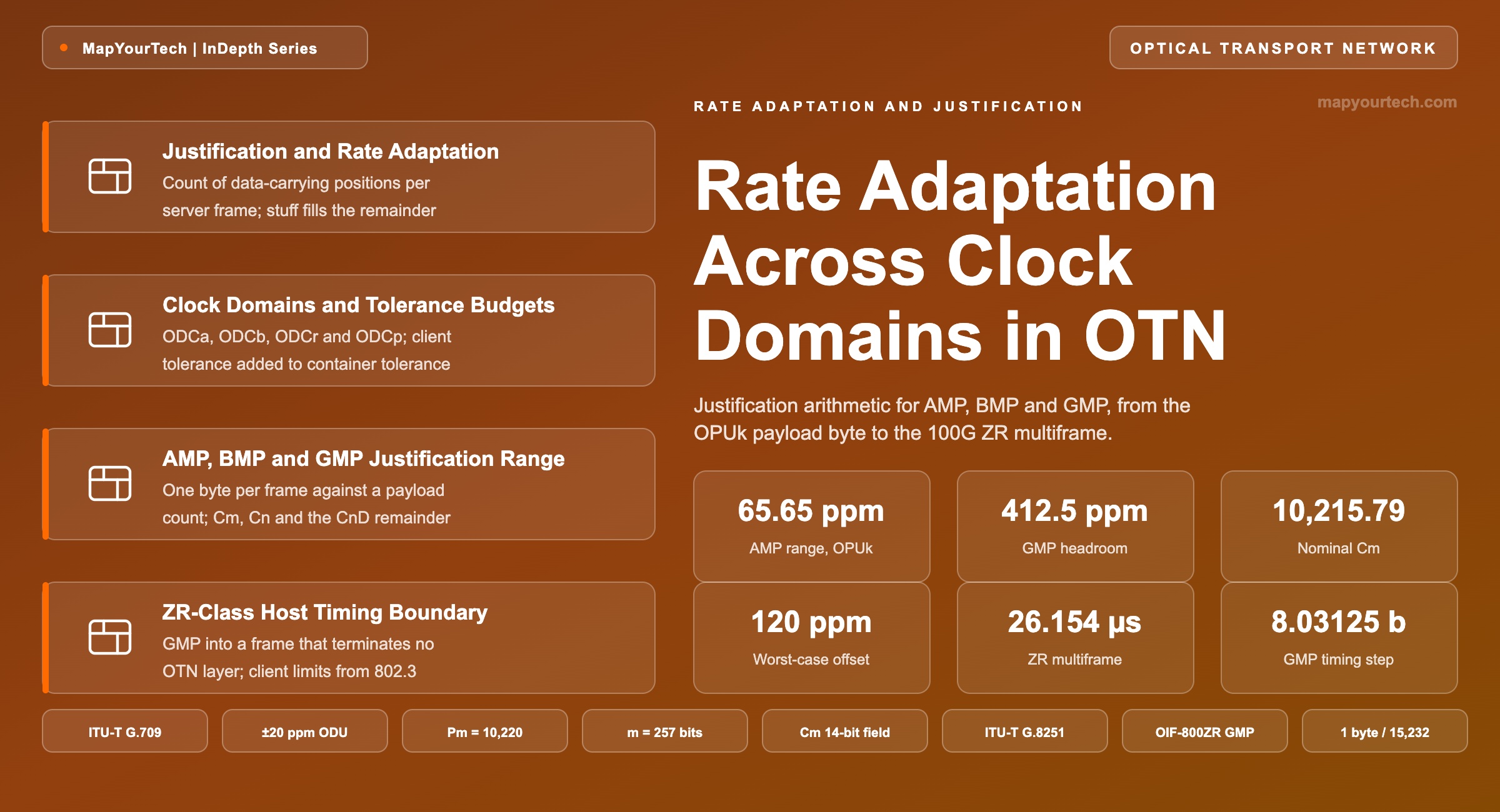
Rate Adaptation Across Clock Domains in OTN
How AMP, BMP and GMP absorb the frequency difference between a client and an independently clocked line container, how much each can absorb, and what happens at the edge of the justification range.
The parameter nobody owns is the parameter that fails.
What You Will Learn
- Define justification and the rate adaptation function from the count of data-carrying positions per server frame, using the anatomy of Figure 1.
- Place the ±20 ppm ODU tolerance and the ±100 ppm Ethernet and ODUflex tolerances against the four ODU clock types of Table 2.
- Quantify the AMP justification range as one byte in 15,232, or ±65.65 ppm, and check it against the ±40 ppm the ±20/±20 design case demands.
- Construct the GMP parameter set — m, n, Pm, Cm, Cn and ΣCnD — and read the JC1 to JC6 overhead that carries it.
- Work 100GE into one 100G ZR instance through to Cm = 10,215.79 against Pm = 10,220, and read the 412.5 ppm of headroom that follows.
- Convert the 257-bit mapping quantum into a 97.89 ppm frequency step and show why the 5-bit CnD field reduces phase quantization by a factor of 32.
- Select a mapping procedure against client tolerance, jitter target and equipment class using the decision table of Section 12.
- Anchor the ZR-class timing boundary: a ±100 ppm host client, a ±20 ppm line, and no ODU layer to carry the G.8251 de-mapper requirement.
1. Introduction
A 100 Gigabit Ethernet source is allowed to run anywhere inside ±100 ppm of its nominal signalling rate (standard-specified, IEEE Std 802.3). The coherent line interface that carries it runs on a different oscillator, held to ±20 ppm for optical transport network (OTN) signals (standard-specified, ITU-T G.709). Neither oscillator is disciplined to the other, and neither is required to be. At the worst combination the two frequencies differ by 120 ppm, which at 100 Gb/s amounts to 12 Mbit of data per second that the container either cannot accept or cannot fill. No buffer absorbs that indefinitely, so the mapping function has to change the amount of client data it carries in every frame it sends. That per-frame adjustment is justification, and the family of procedures that performs it — the Asynchronous Mapping Procedure (AMP), the Bit-synchronous Mapping Procedure (BMP) and the Generic Mapping Procedure (GMP) — is the subject here.
Three things make this a design decision rather than an implementation detail. First, each procedure has a finite justification range, and a client whose tolerance exceeds that range cannot be carried: AMP into an OPU1 supplies about ±65.65 ppm of adjustment, which covers a ±20 ppm client against a ±20 ppm container and fails a ±100 ppm client. Second, every justification event moves the client's recovered phase by the size of the adjustment quantum, so the choice of procedure sets the mapping jitter the far-end de-mapper has to filter before it can drive a client interface. Third, the procedures differ in what they demand of the equipment clock: BMP requires the container clock to be locked to the client, which removes justification entirely and also removes the ability to multiplex independent clients into one container.
The applications that make this current are not legacy ones. ODUflex sizing for Ethernet private line, FlexE-aware transport, and the mapping of 100GE through 800GE into coherent pluggable frames all rest on the same arithmetic, and the pluggables have moved it out of a transponder shelf and onto a router faceplate — a shift covered in the MapYourTech walkthrough of IP over DWDM architecture. A planner who sizes an ODUflex without checking the container tolerance, or an operator who sees intermittent client-side bit errors on one direction of a link only, is looking at this mechanism whether or not they name it.
The scope here is the rate adaptation function itself: what each procedure absorbs, the arithmetic that bounds it, the overhead that carries the control information, and the behaviour at the edge of the range. Frequency distribution across a network — synchronous Ethernet, the synchronization status message, and the timing chain that feeds a network element's own reference — sits above this boundary and is treated separately in the MapYourTech reference on OTN clock and synchronization.
2. Justification and the Rate Adaptation Function
Rate adaptation is the process that lets a client bit stream of one frequency occupy a server container clocked at another. The mapper writes client data into a fixed number of payload positions per server frame and fills the positions it cannot supply with stuff bits; justification is the per-frame decision of how many of those positions carry data. The count travels to the de-mapper in dedicated overhead.
Every part of that definition is a physical object in the frame. The payload positions are byte columns or bit blocks at fixed offsets. The stuff bits are transmitted as zeros and discarded on receive. The count is a number encoded in named overhead bytes and protected by a checksum. Figure 1 shows the arrangement.
Read the Full Analysis with Premium
The remaining 88% of this article — the design numbers, trade-offs and field guidance — is part of MapYourTech Premium, along with the full premium library, courses and professional tools.
You May Also Like

-
Free
-
September 4, 2026

-
Premium
-
September 4, 2026

-
Premium
-
September 4, 2026