FEC Families for Coherent Interfaces: CFEC and OFEC
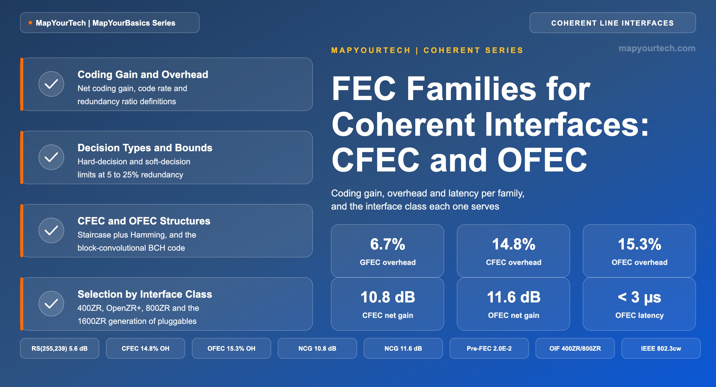
Hard-decision and soft-decision coding, net coding gain, overhead and latency per family, and the interface class each one serves.
Every bit matters, but how you transmit them matters more.
1. Introduction
A 400ZR module in normal service reports a pre-FEC bit error ratio near 1 × 10⁻² while delivering client traffic with no errors at all. The raw channel is running at roughly one error per hundred bits, and the decoded payload sits below a design error floor of 1 × 10⁻¹⁵ (standard-specified, OIF 400ZR Implementation Agreement). Forward error correction (FEC) spans that distance, and the span is the largest single lever in a coherent link budget: current coherent codes return 10–12 dB of net coding gain, more than any amplifier or fiber choice available to the designer.
Four code families are in service on coherent interfaces. Hard-decision (HD) codes carry the OTN heritage and the 100 Gb/s DWDM Ethernet interface. Proprietary soft-decision (SD) codes sit inside vendor transponders for long-haul and submarine reach. Concatenated FEC (CFEC) serves the 400 Gb/s data center interconnect (DCI) class. Open FEC (OFEC) serves everything the industry has standardized since, from OpenZR+ through 800ZR and into the 1600ZR work. Each buys its gain at a different price in overhead, decoder effort and delay.
This article defines coding gain and net coding gain as the ITU-T G-series states them, separates hard-decision from soft-decision decoding and their theoretical limits, gives overhead, gain, pre-FEC threshold and latency for each family, and maps each family to the interface class it serves. The optical signal-to-noise ratio relationships behind these numbers are treated separately; here the subject is the coding layer that consumes the margin they produce.
2. Coding Gain, Net Coding Gain and Overhead
Coding gain is the reduction in required signal-to-noise ratio at a stated reference bit error ratio, measured against a theoretical reference receiver in white Gaussian noise. Net coding gain (NCG) is that value corrected for the noise increase caused by the bandwidth expansion the parity bits force on the receiver. The distinction is the one that decides whether two codes can be compared at all, and ITU-T G-series Supplement 39 defines both terms along with code rate R, the Qb factor, BERin and BERout (standard-specified, ITU-T G-series Supplement 39, clause 11).
In-band FEC needs no correction, because its parity bits occupy previously unused section overhead and the line rate does not rise. The shortened BCH(4359,4320) code of ITU-T G.707 is the SDH example: code rate 1, and coding gain equal to net coding gain at 3.8 dB for a reference BER of 1 × 10⁻¹² (standard-specified, ITU-T G-series Supplement 39, Table 11-2). Every coherent code in this article is out-of-band: parity raises the line rate, the receiver integrates noise over a wider bandwidth, and the raw coding gain overstates the benefit by 10·log10(1/R).
NCG(dB) = 20·log10[erfc-1(2·BERref)] − 20·log10[erfc-1(2·BERin)] + 10·log10(R)Where:
BERref — reference output bit error ratio, typically 1 × 10⁻¹² in ITU-T G-series work and 1 × 10⁻¹⁵ in coherent interface agreements
BERin — the highest input bit error ratio the decoder reduces to BERref; the pre-FEC threshold quoted on a datasheet
R — code rate, the ratio of the rate without FEC to the rate with FEC; R = 1 for in-band FEC, 0.80–0.95 for coherent out-of-band codes
erfc−1 — inverse complementary error function
Expressed in 20·log10Qb, net coding gain equals the allowable OSNR reduction whenever amplified spontaneous emission is the only meaningful noise source at the decision circuit.
Overhead follows directly from code rate, and the two are quoted interchangeably in datasheets even though they are different numbers. A 15% overhead code has a code rate of 0.870, not 0.85, and using the wrong one shifts the third term of Equation 1 by 0.2 dB.
R = k / n OH = (n − k) / k = (1 / R) − 1Where:
n — code word length in bits or symbols; k — information bits or symbols per code word
OH — redundancy ratio, expressed as a percentage of the information rate, which is what "15% FEC" means on a line card
For concatenated codes the rates multiply: OHtotal = (1/(Router · Rinner)) − 1
Practical Example — overhead of three deployed codes
RS(255,239) carries 16 parity bytes per 239 information bytes, giving OH = 16/239 = 6.7% and R = 239/255 = 0.937. The OFEC constituent code is an extended BCH(256,239) with 17 parity bits per 111 information bits in the block-convolutional structure, giving OH = 17/111 = 15.3% (standard-specified, OIF 800ZR Implementation Agreement, clause 5.7). CFEC concatenates an outer staircase code of rate 0.937 with an inner Hamming code of rate 0.930, so OH = 1/(0.937 × 0.930) − 1 = 14.8%, matching the figure quoted in the 400ZR agreement.
Takeaway: Compare codes only at the same reference BER and only through net coding gain. A gain figure quoted at 1 × 10⁻¹⁵ is roughly 1 dB larger than the same code quoted at 1 × 10⁻¹², which is enough to invert a ranking if the reference is not checked.
3. Hard-Decision and Soft-Decision Decoding
Hard-decision decoding quantizes each received bit to two levels: the sample is a one or a zero, and the decoder works from that alone. Soft-decision decoding quantizes to more than two levels, so each bit arrives with confidence information attached. Two-bit soft decision resolves a sample into strong zero, weak zero, weak one and strong one; practical coherent receivers use more than two bits, and the additional resolution is what the decoder converts into gain (standard-specified, ITU-T G-series Supplement 39, clause 11.4).
The theoretical limits differ by channel model. Hard-decision bounds derive from a binary symmetric channel, soft-decision bounds from a binary-input additive white Gaussian noise channel, and at equal redundancy the soft-decision bound sits 1.1–1.3 dB above the hard-decision bound across the 5–25% range. That gap is the whole reason every coherent code standardized since 400ZR uses soft-decision decoding on at least one stage.
| Redundancy ratio | Code rate R | HD bound at 10−12 | SD bound at 10−12 | HD bound at 10−15 | SD bound at 10−15 |
|---|---|---|---|---|---|
| 5% | 0.952 | 8.6 dB | 9.7 dB | 9.6 dB | 10.7 dB |
| 7% | 0.935 | 9.0 dB | 10.1 dB | 10.0 dB | 11.2 dB |
| 10% | 0.909 | 9.4 dB | 10.6 dB | 10.5 dB | 11.6 dB |
| 15% | 0.870 | 9.9 dB | 11.2 dB | 11.0 dB | 12.2 dB |
| 20% | 0.833 | 10.3 dB | 11.6 dB | 11.3 dB | 12.6 dB |
| 25% | 0.800 | 10.6 dB | 11.9 dB | 11.6 dB | 12.9 dB |
Two properties of the plot carry into design work. CFEC sits about 0.2 dB below the hard-decision bound at its own redundancy, which is a deliberate trade for decoder simplicity rather than a shortfall. OFEC clears the hard-decision bound at the same overhead and lands roughly 0.6 dB short of the soft-decision bound, so the remaining headroom is small and the next increment of gain has to be bought with more overhead, more decoding passes, or constellation shaping. Both codes are close enough to their limits that the rest of the link budget now dominates reach.
Takeaway: Soft-decision decoding is worth 1.1–1.3 dB over hard decision at equal overhead, and deployed coherent codes now run within about 0.6 dB of their own theoretical bound. Gain is no longer where the easy improvement lives.
4. FEC Families in Coherent Line Interfaces
All four families occupy the same two positions in the signal chain: an outer stage that cleans up whatever the inner stage leaves behind, and an inner stage that does the heavy correction using soft information from the receiver. What changes between families is which stage exists, how it decides, and how deeply the interleaver spreads a burst.
4.1 Hard-Decision Codes: Reed-Solomon and Staircase
RS(255,239) is the ITU-T G.709 out-of-band code, widely called GFEC. It corrects up to eight bytes per code word, and 16-byte interleaving in the G.709 frame lets it absorb 1,024 contiguous error bits. It reduces an input BER of 1.8 × 10⁻⁴ to 1 × 10⁻¹² at a net coding gain of 5.6 dB and a code rate of 239/255 (standard-specified, ITU-T G-series Supplement 39, Table 11-2). That was enough for 10 Gb/s direct-detection systems and is far short of what a coherent receiver needs.
The modern hard-decision code is the staircase code, at the same 6.7% overhead but with much higher gain, and it is the code behind two current interfaces: G.709.2 OTU4-SC and the IEEE 802.3ct 100GBASE-ZR PHY use the same staircase FEC, a point ITU-T Study Group 15 and the IEEE 802.3 Beyond 400G group aligned on deliberately (standards-body contribution, ITU-T liaison presentation to IEEE 802.3, 2021). Staircase codes are the outer stage of CFEC as well, so the family did not disappear — it moved inward.
4.2 Soft-Decision Codes in Vendor Line Interfaces
Proprietary SD-FEC is where the industry put its highest-gain codes before interoperable pluggables existed, and it is still where the deepest long-haul and submarine performance lives. These codes are low-density parity-check or turbo product constructions at 15%, 20% or 25% overhead with iterative soft-decision decoding. Published net coding gains of 11.5–12 dB are typical for the class (vendor claim, optical systems vendor technical blog), and one commercial coherent module family specifies its internal 15% soft-decision mode at 11.5 dB net coding gain for QPSK, 12.0 dB for 16QAM and 12.5 dB for 64QAM against a pre-FEC BER threshold of 2.4 × 10⁻² (vendor claim, coherent module product specification).
The cost is interoperability. Two proprietary SD-FEC endpoints from different vendors do not talk to each other, which is what created demand for the two interoperable codes that follow. Decoder power and delay also scale with the number of iterative passes, so the same silicon usually offers a reduced-iteration mode that trades a few tenths of a dB for lower latency.
4.3 CFEC: Concatenated Staircase and Hamming
CFEC combines a hard-decision outer staircase code, the same construction used at 100G, with a soft-decision inner double-extended Hamming(128,119) code, at 14.8% total overhead. It delivers 10.8 dB net coding gain for DP-16QAM with a post-FEC error floor below 1 × 10⁻¹⁵ (standard-specified, OIF 400ZR Implementation Agreement). Published pre-FEC BER thresholds for the code cluster at 1.22 × 10⁻² and 1.25 × 10⁻² depending on the reference receiver assumed, so treat roughly 1.2 × 10⁻² as the working number and take the exact value from the module datasheet before setting an alarm threshold.
The design point was low decoder effort rather than maximum gain. A 400G implementation of the decoder was presented at 420 mW in a 7 nm process with 1,024-bit burst tolerance (vendor contribution to IEEE 802.3, 2018), which is what allowed a full coherent DSP to fit a QSFP-DD thermal envelope. The same code appears in IEEE 802.3cw 400GBASE-ZR and in the ITU-T G.709.3 FlexO4-DSH interface, so an Ethernet PHY and an OTN interface at 400G now share one code.
4.4 OFEC: Open FEC Block Turbo Code
OFEC is a block-convolutional code with iterative soft-decision decoding, built from an extended BCH(256,239) constituent code arranged in a semi-infinite matrix of 128-bit columns. Each bit belongs to two constituent code words, one at its front and one at its back, and a bit-reversal permutation inside each 16 × 16 square block removes the weight-36 error events a plain product code would carry, lifting the minimum Hamming distance of the full code to at least 42 (standard-specified, OIF 800ZR Implementation Agreement, clause 5.7). Parity occupies 17 bits per 111, so overhead is 15.3%.
With three soft-decision iterations the code returns 11.1 dB net coding gain for DP-QPSK and 11.6 dB for DP-16QAM at a reference BER of 1 × 10⁻¹⁵, against a pre-FEC BER threshold of 2.0 × 10⁻², and combined encoder plus decoder latency is under 3 µs (standard-specified, OpenZR+ MSA). The higher pre-FEC threshold is as useful operationally as the extra gain: it widens the range over which pre-FEC BER trend alarms stay meaningful before the link approaches its cliff.
OFEC has become the default. It carries OpenZR+, Open ROADM, the OIF 800ZR agreement published in October 2024, and the 1600ZR and 1600ZR+ projects now in progress, with implementation agreements targeted for the second and third quarters of 2026 (standards-status figures, OIF project scope and industry conference reporting from OFC 2026). Interface-level consequences of that transition are covered separately in the 1600ZR-class pluggable analysis.
A coherent link running CFEC and a link running OFEC have different pre-FEC BER dynamic ranges, so a single alarm template applied to both will over-alarm on one and under-alarm on the other. Set the guard band from the code in use, not from the port count, and read the code from the module's application code rather than assuming it from the form factor.
5. Comparative Specification of the Four Families
The table below collects the specification points that decide a design. Read the overhead and gain columns together: gain per unit of overhead falls steeply across the range, so the last dB is always the most expensive one.
| Family | Code structure | Decision | Overhead | Net coding gain | Pre-FEC BER threshold | Latency | Interface class |
|---|---|---|---|---|---|---|---|
| HD-FEC (GFEC) | RS(255,239), 16-byte interleave | Hard | 6.7% | 5.6 dB at 10−12 | 1.8 × 10⁻⁴ | Lowest of the four | OTN OTUk line interfaces, legacy 10G and 40G systems |
| HD-FEC (staircase) | Staircase BCH product construction | Hard | 6.7% | Below the 10.0 dB HD bound at 7% | Not published as a single figure | Low | ITU-T G.709.2 OTU4-SC, IEEE 802.3ct 100GBASE-ZR |
| SD-FEC (proprietary) | LDPC or turbo product, iterative | Soft | 15–25% | 11.5–12.5 dB (vendor claim) | Up to 2.4 × 10⁻² (vendor claim) | Highest; scales with iteration count | Vendor transponders, long-haul and submarine |
| CFEC | HD staircase outer + SD Hamming(128,119) inner | Hard outer, soft inner | 14.8% | 10.8 dB at 10−15 (16QAM) | ≈ 1.2 × 10⁻² | Low; single inner pass | OIF 400ZR, IEEE 802.3cw 400GBASE-ZR, ITU-T G.709.3 FlexO4-DSH |
| OFEC | Block-convolutional, extended BCH(256,239) constituents | Soft, three iterations | 15.3% | 11.1 dB QPSK / 11.6 dB 16QAM at 10−15 | 2.0 × 10⁻² | Under 3 µs encode plus decode | OpenZR+, Open ROADM, OIF 800ZR, 1600ZR work |
Three comparisons carry most of the engineering value. OFEC returns 0.3 dB more than CFEC on QPSK and 0.8 dB more on 16QAM for half a percent more overhead, which is the clearest gain-per-overhead bargain in the set. The step from GFEC to any coherent code is worth more than 5 dB, which is why a legacy OTN margin figure cannot be carried across to a coherent line. And the proprietary SD-FEC advantage over OFEC is now a few tenths of a dB, small enough that interoperability usually wins the argument outside submarine plant.
Takeaway: On a coherent line the practical choice is CFEC or OFEC, and the deciding factor is rarely the 0.3–0.8 dB of gain by itself. It is whether the link needs the higher 2.0 × 10⁻² pre-FEC threshold and the reach that comes with it.
6. Line Rate, Overhead and Latency Arithmetic
FEC overhead is only part of what separates a client rate from a symbol rate. Pilot symbols, alignment markers and frame overhead take their own share, and mixing them up produces a symbol rate that misses by several percent. The chain runs client rate, transcoding, FEC parity, framing, pilots, then symbol rate.
Rline = Rclient × (1 + OHFEC) × (1 + OHframe) × (1 + OHpilot)

Rs = Rline / (2 · m)
Where:
Rclient — client bit rate after transcoding, for example 400 × 257/256 = 401.56 Gb/s for a 256b/257b transcoded 400GbE client
OHFEC — FEC redundancy ratio: 0.148 for CFEC, 0.153 for OFEC
OHframe, OHpilot — frame and pilot-symbol overheads; 400ZR inserts one pilot symbol every 32 QAM symbols, so OHpilot = 1/31 = 3.2%
m — bits per symbol per polarization, 4 for 16QAM and 2 for QPSK; the factor 2 covers the two polarizations
Rs — symbol rate in GBd, the number the filter and grid plan are built from
Practical Example — 400ZR overhead accounting at 59.84375 GBd
Work the chain backwards from the standard-specified 400ZR symbol rate of 59.84375 GBd (OIF 400ZR Implementation Agreement). DP-16QAM carries 8 bits per symbol, so the gross line rate is 59.84375 × 8 = 478.75 Gb/s. Removing one pilot symbol in every 32 leaves 478.75 × 31/32 = 463.79 Gb/s. Removing CFEC parity divides by 1.148 and leaves 404.0 Gb/s. The transcoded 400GbE client accounts for 401.56 Gb/s of that, so 2.4 Gb/s, or 0.6%, remains for alignment markers and frame overhead. The chain closes, and it shows where each percent goes: 14.8 points to parity, 3.2 to pilots, 0.6 to framing (derived values, from standard-specified inputs).
Latency follows the same structure. A FEC engine holds bits while it waits for the rest of a code word and for the interleaver to unwind, so delay is stored bits divided by line rate. Interleaver depth, not code strength, sets the number.
TFEC ≈ Nstored / RlineWhere:
Nstored — bits held in the encoder pipeline, the interleaver and the decoder iteration memory
Rline — gross line bit rate from Equation 3
The relation explains why the same code costs less delay as rates rise: doubling the line rate halves the time a fixed block occupies.
Practical Example — OFEC interleaver delay at a 400G line rate
The OFEC interleaver block is 172,032 bits and the code uses two parallel interleavers, so 344,064 bits are in flight per pass (standard-specified, OIF 800ZR Implementation Agreement, clause 5.8). A 400G OpenZR+ line runs at 60.138546798 GBd, giving a gross line rate of 481.1 Gb/s, so one interleaver pass costs 344,064 / 481.1 Gb/s = 0.72 µs (derived). Encoder pipeline memory, three soft-decision decoding iterations and the deinterleaver add the rest, which is consistent with the under-3 µs combined figure the MSA specifies. Against a fiber propagation delay near 4.9 µs/km, the whole code costs less than one kilometre of fiber — decisive on a 10 km span, irrelevant on a 500 km one, as the latency breakdown for OTN and ZR interfaces sets out in full.
Takeaway: FEC overhead sets symbol rate and therefore channel width; interleaver depth sets latency. They are independent choices, and a code with more overhead is not automatically the slower one.
7. FEC Selection by Interface Class
On an interoperable pluggable the code is not really a free choice: it is fixed by the application code the two endpoints agree on, and the reach class follows from it. The selection question in practice is which interface class the link belongs to.
| Interface class | Client and line | Code | Application | Governing specification |
|---|---|---|---|---|
| 100G DWDM Ethernet | 100GbE over a single wavelength | Staircase HD | Amplified single-span metro and DCI | IEEE 802.3ct, ITU-T G.709.2 |
| 400G DCI | 400GbE, DP-16QAM at 59.84375 GBd | CFEC | Amplified links to about 120 km, unamplified to about 40 km | OIF 400ZR, IEEE 802.3cw |
| 400G multi-haul | 100G to 400G, QPSK through 16QAM | OFEC | Metro to regional, multi-span and ROADM traversal | OpenZR+ MSA, Open ROADM MSA |
| 800G DCI | 100GbE to 800GbE clients on one line | OFEC | Single-span amplified DWDM, 80–120 km | OIF 800ZR |
| 1600G class | 1.6T line, DP-16QAM, PCS on the plus variant | OFEC | DCI and, on the plus variant, metro and long haul | OIF 1600ZR and 1600ZR+ projects in progress |
| Long-haul and submarine | Vendor transponder line interface | Proprietary SD-FEC | Multi-span terrestrial long haul, submarine cable | Vendor specification, matched endpoints |
Three practical points follow from the table. First, an interface class change is a code change, so a link upgraded from 400ZR to OpenZR+ moves its pre-FEC threshold from about 1.2 × 10⁻² to 2.0 × 10⁻² and every alarm threshold set against the old value has to move with it. Second, a mixed estate needs per-application-code baselines in the monitoring layer, because a single template cannot serve both. Third, acceptance testing has to record which code was active during the measurement, since a back-to-back required-OSNR figure is only meaningful alongside its code and modulation format, a point covered in the coherent transponder test reference.
Where a link falls between classes — long enough that CFEC will not close but short enough that a transponder is hard to justify — the useful lever is usually elsewhere in the budget rather than in the code: amplifier placement, launch power, or the Q-factor improvement techniques that address specific impairments. The coding layer has already given up almost everything it has.
8. Summary
Net coding gain is the only fair comparison between out-of-band codes, and it must be read at a stated reference BER. Hard-decision codes stop around 6.7% overhead and 5.6 dB in their legacy form; the modern staircase code at the same overhead carries the 100G DWDM Ethernet PHY. CFEC concatenates that staircase code with a soft-decision Hamming inner code for 10.8 dB at 14.8% overhead, and serves the 400G DCI class. OFEC returns 11.1 dB on QPSK and 11.6 dB on 16QAM at 15.3% overhead with a 2.0 × 10⁻² pre-FEC threshold and under 3 µs of combined encode and decode delay, and it now carries OpenZR+, Open ROADM, 800ZR and the 1600ZR work. Proprietary soft-decision codes keep a few tenths of a dB more for long-haul and submarine plant at the cost of interoperability.
Quick reference values worth keeping: 6.7% and 5.6 dB for GFEC at 10−12; 14.8% and 10.8 dB for CFEC at 10−15; 15.3% and 11.1 or 11.6 dB for OFEC at 10−15; pre-FEC thresholds of roughly 1.2 × 10⁻² and 2.0 × 10⁻² respectively; and a soft-decision advantage of 1.1–1.3 dB over hard decision at equal redundancy. For the surrounding budget arithmetic, the optical link engineering formula reference and the Q-factor definition carry the conversions that turn these gains into reach.
References
- ITU-T G-series Supplement 39 — Optical system design and engineering considerations, ITU-T Study Group 15.
- ITU-T Recommendation G.709 — Interfaces for the optical transport network, ITU-T Study Group 15.
- Optical Internetworking Forum — Implementation Agreement for 400ZR (OIF-400ZR), Optical Internetworking Forum.
- Optical Internetworking Forum — Implementation Agreement for 800ZR Coherent Interfaces (OIF-800ZR), Optical Internetworking Forum.
- OpenZR+ Multi-Source Agreement — OpenZR+ 400G Digital Coherent Optics for Multi-Haul, OpenZR+ MSA.
- IEEE Std 802.3ct — Physical Layers and Management Parameters for 100 Gb/s Operation over DWDM Systems, IEEE.
- Sanjay Yadav, "Optical Network Communications: An Engineer's Perspective" — Bridge the Gap Between Theory and Practice in Optical Networking.
Related Articles on MapYourTech